relay VOLVO XC70 2004 Owners Manual
[x] Cancel search | Manufacturer: VOLVO, Model Year: 2004, Model line: XC70, Model: VOLVO XC70 2004Pages: 241, PDF Size: 5.78 MB
Page 149 of 241

2004 VOLVO XC70
pg. 118 Fuses
Replacing fuses
If an electrical component fails to function, it is possible that a fuse\
has blown due to a temporary circuit
overload.
Fuses are located in different places:
A - Relays/fuse box in the engine compartment
B - Fuse box in the passenger compartment
C - Relays/fuse box in the cargo area
A label on the inside of each cover indicates the amperage and the elect\
rical components that are
connected to each fuse.
The easiest way to see if a fuse is blown is to remove it. Pull the fuse\
straight out. If a fuse is difficult to
remove, you will find a special fuse removal tool in the passenger compa\
rtment fuse box. From the side,
examine the curved metal wire to see if it is broken. If so, put in a ne\
w fuse of the same color and
amperage (written on the fuse). Spare fuses are stored in the fuse box in the \
passenger compartment. If
fuses burn out repeatedly, have the electrical system inspected by an au\
thorized Volvo retailer.
WARNING!
Never use fuses with higher amperage that those stated on the following \
pages. Doing so could
overload the car's electrical system.
file:///K|/ownersdocs/2004/2004_XC70/04xc70_08a.htm (2 of 22)12/30/200\
6 4:33:05 PM
Page 150 of 241

2004 VOLVO XC70
pg. 119 Fuses in the engine compartment
Relays/fuses in the engine compartment
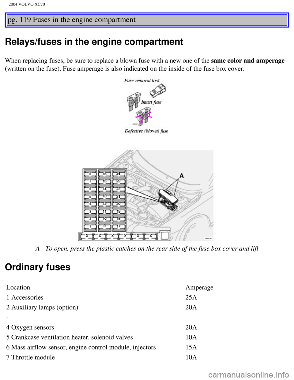
When replacing fuses, be sure to replace a blown fuse with a new one of \
the same color and amperage
(written on the fuse). Fuse amperage is also indicated on the inside o\
f the fuse box cover.
A - To open, press the plastic catches on the rear side of the fuse box \
cover and lift
Ordinary fuses
Location Amperage
1 Accessories 25A
2 Auxiliary lamps (option) 20A
-
4 Oxygen sensors 20A
5 Crankcase ventilation heater, solenoid valves 10A
6 Mass airflow sensor, engine control module, injectors 15A
7 Throttle module 10A
file:///K|/ownersdocs/2004/2004_XC70/04xc70_08a.htm (3 of 22)12/30/200\
6 4:33:05 PM
Page 153 of 241

2004 VOLVO XC70
24 Relay for extended D1 feed: climate control system, power driver's se\
at, driver's
info 10A
25 Ignition switch, relay starter motor, SRS, engine control module 10A
26 Climate control system blower 30A
27 -
28 Electronic module - courtesy lighting 10A
29 -
30 Left front/rear parking lights 7.5A
31 Right front/rear parking lights, license plate lights 7.5A
32 Central electrical module, vanity mirror lightings,
glove compartment light, interior courtesy lighting 10A
33 Fuel pump 15A
34 Power moonroof 15A
35 Central locking system, power windows - left door mirror 25A
36 Central locking system, power windows - right door mirror 25A
37 Rear power windows 30A
38 Alarm siren 5A
* Please be aware that if this fuse is not intact, or if it is removed, \
the alarm will sound.
pg. 121 Fuses in the cargo area
Fuses in the cargo area
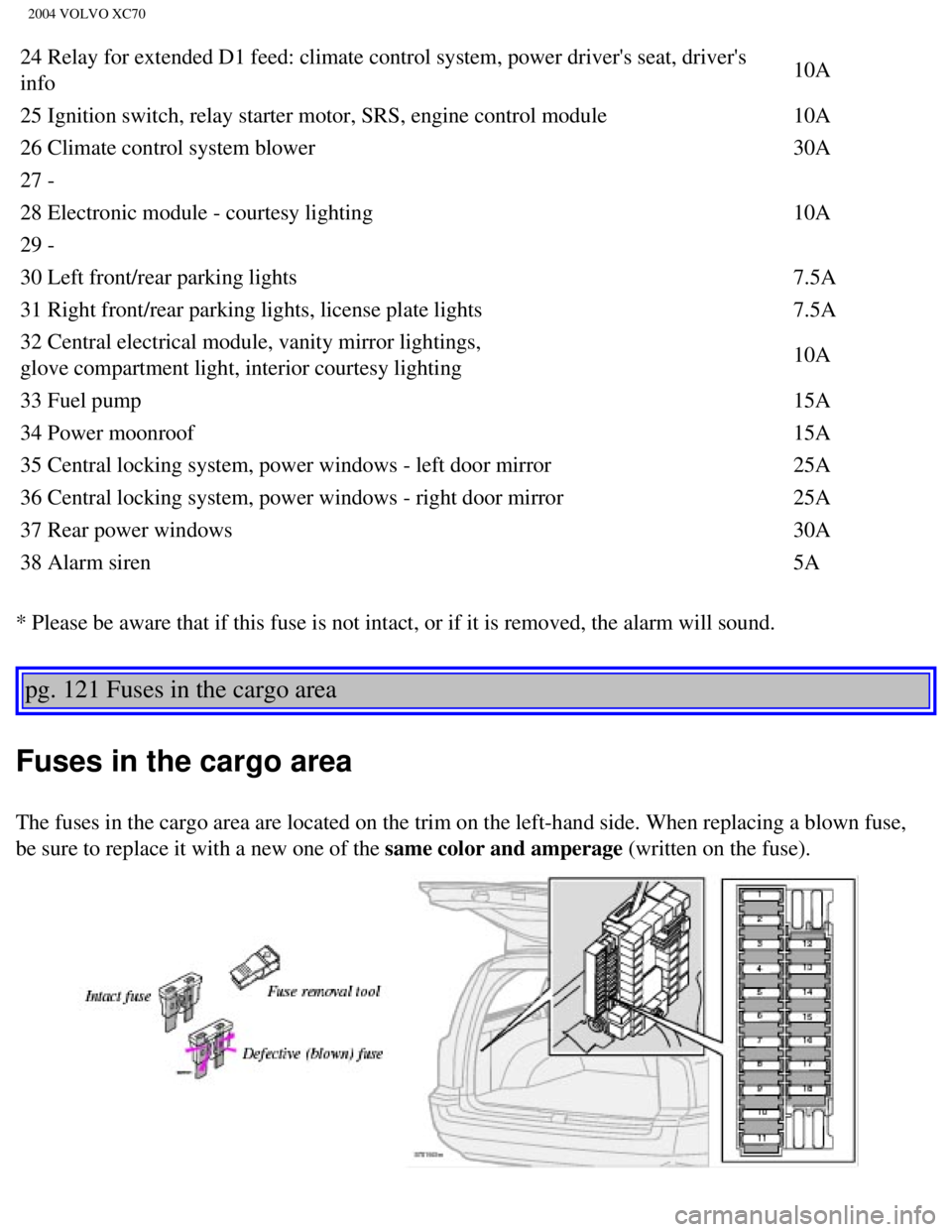
The fuses in the cargo area are located on the trim on the left-hand sid\
e. When replacing a blown fuse,
be sure to replace it with a new one of the same color and amperage (written on the fuse).
file:///K|/ownersdocs/2004/2004_XC70/04xc70_08a.htm (6 of 22)12/30/200\
6 4:33:05 PM
Page 154 of 241

2004 VOLVO XC70
Ordinary fuses
Location Amperage
1 Rear electrical module, cargo area lighting 10A
2 Rear fog light 10A
3 Brake lights 15A
4 Backup lights 10A
5 Rear window defroster, relay 15I -
accessories 5A
6 Unlocking tailgate 10A
7 Auxiliary 12 volt socket in cargo area
(option) 15A
8 Central locking rear doors/fuel filler door 20A
9 Trailer hitch(30 feed) 15A
10 CD changer, VNS 10A
11 Accessory control module (AEM) 15A
12 Tailgate wiper 15A
13 Loudspeaker (subwoofer) cargo area -
option 15A
14 Brake lights 7.5A
15 Trailer hitch (15I feed) 20A
16 -
17 All Wheel Drive control module 7.5A
18 -
pg. 122 Replacing bulbs
file:///K|/ownersdocs/2004/2004_XC70/04xc70_08a.htm (7 of 22)12/30/200\
6 4:33:05 PM
Page 176 of 241

2004 VOLVO XC70
Engine compartment
1 Expansion tank - coolant
2 Power steering fluid reservoir
3 Washer fluid reservoir
4 Dipstick - engine oil
5 Radiator/cooling fan
6 Oil filler cap - engine
7 Brake fluid reservoir
8 Relay/fuse box
9 Air cleaner
10 Battery (in the cargo compartment) WARNING!
The cooling fan may start or continue to operate (for up to 6 minutes)\
after the engine has been
switched off.
pg. 137 Engine oil
Oil quality
Engine oil must meet the minimum ILSAC specification GF-2, including ACE\
A A1, API SJ, SJ/CF and
SJ/Energy Conserving.
Your Volvo has been certified to standards using ILSAC oil specification\
GF-2 5W-30. Volvo
file:///K|/ownersdocs/2004/2004_XC70/04xc70_08b.htm (7 of 16)12/30/200\
6 4:33:06 PM