ECU VOLVO XC70 2013 Owner´s Manual
[x] Cancel search | Manufacturer: VOLVO, Model Year: 2013, Model line: XC70, Model: VOLVO XC70 2013Pages: 382, PDF Size: 6.78 MB
Page 47 of 382
01 Safety
Booster cushions01
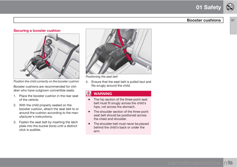
45 Securing a booster cushion
G022851
Position the child correctly on the booster cushion
Booster cushions are recommended for chil-
dren who have outgrown convertible seats.
1. Place the booster cushion in the rear seat
of the vehicle.
2. With the child properly seated on the
booster cushion, attach the seat belt to or
around the cushion according to the man-
ufacturer's instructions.
3. Fasten the seat belt by inserting the latch
plate into the buckle (lock) until a distinct
click is audible.
G022852
Positioning the seat belt
4. Ensure that the seat belt is pulled taut and
fits snugly around the child.
WARNING
•The hip section of the three-point seat
belt must fit snugly across the child's
hips, not across the stomach.
•The shoulder section of the three-point
seat belt should be positioned across
the chest and shoulder.
•The shoulder belt must never be placed
behind the child's back or under the
arm.
Page 48 of 382
01 Safety
ISOFIX/LATCH lower anchors 01
46
Using the ISOFIX/LATCH lower child
seat anchors
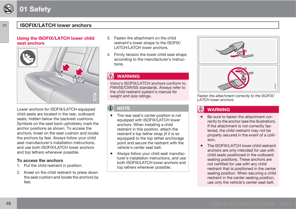
Lower anchors for ISOFIX/LATCH-equipped
child seats are located in the rear, outboard
seats, hidden below the backrest cushions.
Symbols on the seat back upholstery mark the
anchor positions as shown. To access the
anchors, kneel on the seat cushion and locate
the anchors by feel. Always follow your child
seat manufacturer's installation instructions,
and use both ISOFIX/LATCH lower anchors
and top tethers whenever possible.
To access the anchors1. Put the child restraint in position.
2. Kneel on the child restraint to press down
the seat cushion and locate the anchors by
feel.3. Fasten the attachment on the child
restraint's lower straps to the ISOFIX/
LATCH/LATCH lower anchors.
4. Firmly tension the lower child seat straps
according to the manufacturer's instruc-
tions.
WARNING
Volvo's ISOFIX/LATCH anchors conform to
FMVSS/CMVSS standards. Always refer to
the child restraint system's manual for
weight and size ratings.
NOTE
•The rear seat's center position is not
equipped with ISOFIX/LATCH lower
anchors. When installing a child
restraint in this position, attach the
restraint's top tether strap (if it is so
equipped) to the top tether anchorage
point and secure the restraint with the
vehicle's center seat belt.
•Always follow your child seat manufac-
turer's installation instructions, and use
both ISOFIX/LATCH lower anchors and
top tethers whenever possible.
G018631
Fasten the attachment correctly to the ISOFIX/
LATCH lower anchors
WARNING
•Be sure to fasten the attachment cor-
rectly to the anchor (see the illustration).
If the attachment is not correctly fas-
tened, the child restraint may not be
properly secured in the event of a colli-
sion.
•The ISOFIX/LATCH lower child restraint
anchors are only intended for use with
child seats positioned in the outboard
seating positions. These anchors are
not certified for use with any child
restraint that is positioned in the center
seating position. When securing a child
restraint in the center seating position,
use only the vehicle's center seat belt.
Page 49 of 382
01 Safety
Top tether anchors01
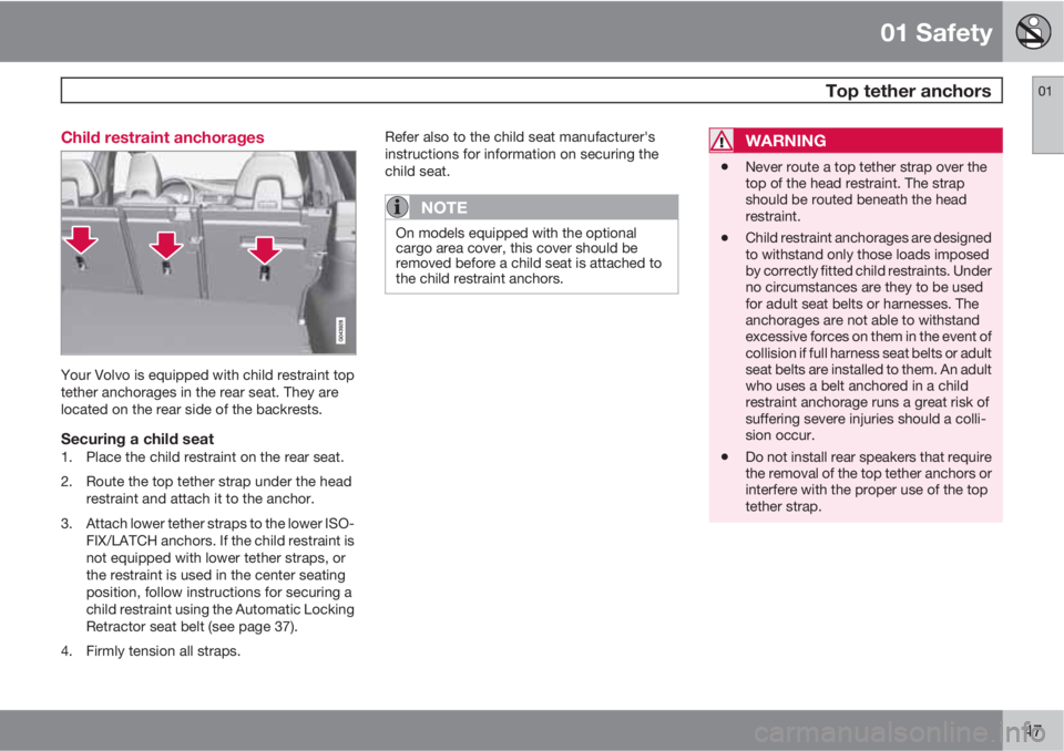
47 Child restraint anchorages
Your Volvo is equipped with child restraint top
tether anchorages in the rear seat. They are
located on the rear side of the backrests.
Securing a child seat1. Place the child restraint on the rear seat.
2. Route the top tether strap under the head
restraint and attach it to the anchor.
3. Attach lower tether straps to the lower ISO-
FIX/LATCH anchors. If the child restraint is
not equipped with lower tether straps, or
the restraint is used in the center seating
position, follow instructions for securing a
child restraint using the Automatic Locking
Retractor seat belt (see page 37).
4. Firmly tension all straps.Refer also to the child seat manufacturer's
instructions for information on securing the
child seat.
NOTE
On models equipped with the optional
cargo area cover, this cover should be
removed before a child seat is attached to
the child restraint anchors.
WARNING
•Never route a top tether strap over the
top of the head restraint. The strap
should be routed beneath the head
restraint.
•Child restraint anchorages are designed
to withstand only those loads imposed
by correctly fitted child restraints. Under
no circumstances are they to be used
for adult seat belts or harnesses. The
anchorages are not able to withstand
excessive forces on them in the event of
collision if full harness seat belts or adult
seat belts are installed to them. An adult
who uses a belt anchored in a child
restraint anchorage runs a great risk of
suffering severe injuries should a colli-
sion occur.
•Do not install rear speakers that require
the removal of the top tether anchors or
interfere with the proper use of the top
tether strap.
Page 50 of 382
01 Safety
Integrated booster cushion 01
48* Option/accessory, for more information, see Introduction.
Integrated two-stage booster
cushion*1
Volvo's optional integrated booster cushions
are located in the outboard seating positions.
These booster cushions have been specially
designed to help safeguard children in the rear
seat. They should be stowed (folded down into
the seat cushion) when not in use. When using
an integrated booster cushion, the child must
be secured with the vehicle's three-point seat
belt.
Use these booster cushions only with
children whose weight is between:
•
Stage 1: 48 – 80 lbs (22 – 36 kg)
•
Stage 2: 33 – 55 lbs (15 – 25 kg)
and whose height is between:
•
Stage 1: 45 – 55 in. (115 – 140 cm)
•
Stage 2: 37 – 47 in. (95 – 120 cm)
In Canada, Transport Canada's
weight recommendation is 40 – 80 lbs
(18 – 36 kg).
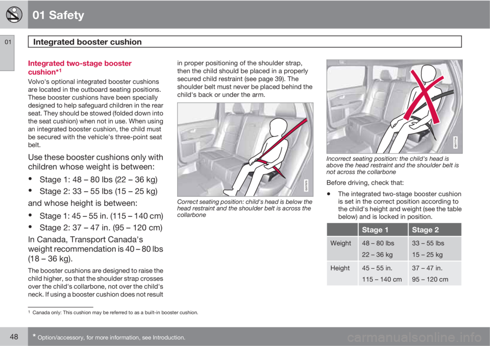
The booster cushions are designed to raise the
child higher, so that the shoulder strap crosses
over the child's collarbone, not over the child's
neck. If using a booster cushion does not resultin proper positioning of the shoulder strap,
then the child should be placed in a properly
secured child restraint (see page 39). The
shoulder belt must never be placed behind the
child's back or under the arm.
G017875
Correct seating position: child's head is below the
head restraint and the shoulder belt is across the
collarbone
G017719
Incorrect seating position: the child's head is
above the head restraint and the shoulder belt is
not across the collarbone
Before driving, check that:
•The integrated two-stage booster cushion
is set in the correct position according to
the child's height and weight (see the table
below) and is locked in position.
Stage 1Stage 2
Weight48 – 80 lbs
22 – 36 kg33 – 55 lbs
15 – 25 kg
Height45 – 55 in.
115 – 140 cm37 – 47 in.
95 – 120 cm
1Canada only: This cushion may be referred to as a built-in booster cushion.
Page 52 of 382
01 Safety
Integrated booster cushion 01
50
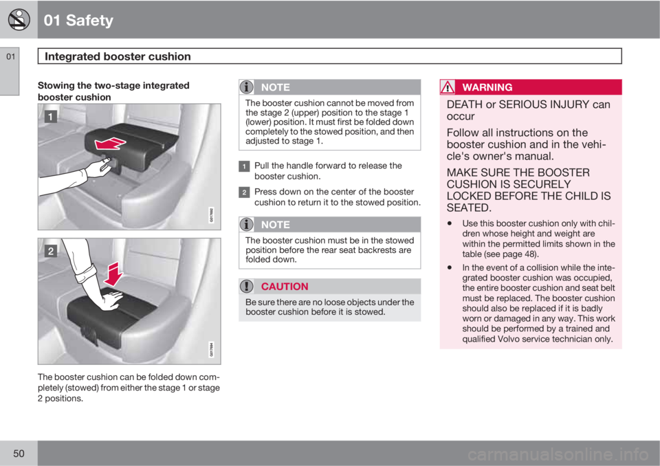
Stowing the two-stage integrated
booster cushion
The booster cushion can be folded down com-
pletely (stowed) from either the stage 1 or stage
2 positions.
NOTE
The booster cushion cannot be moved from
the stage 2 (upper) position to the stage 1
(lower) position. It must first be folded down
completely to the stowed position, and then
adjusted to stage 1.
Pull the handle forward to release the
booster cushion.
Press down on the center of the booster
cushion to return it to the stowed position.
NOTE
The booster cushion must be in the stowed
position before the rear seat backrests are
folded down.
CAUTION
Be sure there are no loose objects under the
booster cushion before it is stowed.
WARNING
DEATH or SERIOUS INJURY can
occur
Follow all instructions on the
booster cushion and in the vehi-
cle's owner's manual.
MAKE SURE THE BOOSTER
CUSHION IS SECURELY
LOCKED BEFORE THE CHILD IS
SEATED.
•
Use this booster cushion only with chil-
dren whose height and weight are
within the permitted limits shown in the
table (see page 48).
•In the event of a collision while the inte-
grated booster cushion was occupied,
the entire booster cushion and seat belt
must be replaced. The booster cushion
should also be replaced if it is badly
worn or damaged in any way. This work
should be performed by a trained and
qualified Volvo service technician only.
Page 86 of 382
03 Your driving environment
Seats
03
84* Option/accessory, for more information, see Introduction.
Front seats
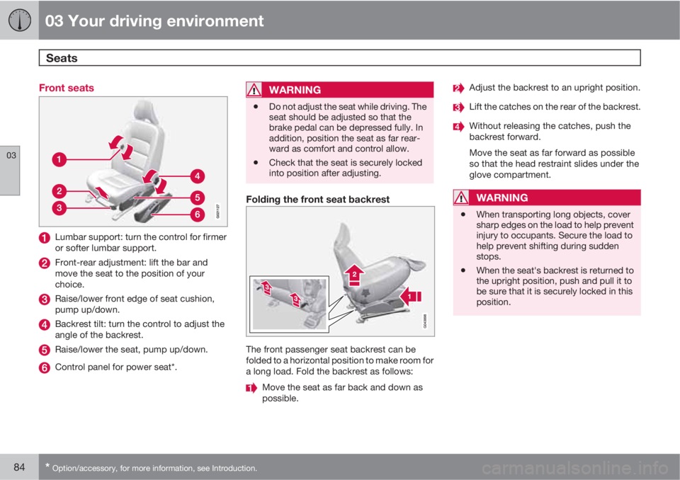
Lumbar support: turn the control for firmer
or softer lumbar support.
Front-rear adjustment: lift the bar and
move the seat to the position of your
choice.
Raise/lower front edge of seat cushion,
pump up/down.
Backrest tilt: turn the control to adjust the
angle of the backrest.
Raise/lower the seat, pump up/down.
Control panel for power seat*.
WARNING
•Do not adjust the seat while driving. The
seat should be adjusted so that the
brake pedal can be depressed fully. In
addition, position the seat as far rear-
ward as comfort and control allow.
•Check that the seat is securely locked
into position after adjusting.
Folding the front seat backrest
The front passenger seat backrest can be
folded to a horizontal position to make room for
a long load. Fold the backrest as follows:
Move the seat as far back and down as
possible.
Adjust the backrest to an upright position.
Lift the catches on the rear of the backrest.
Without releasing the catches, push the
backrest forward.
Move the seat as far forward as possible
so that the head restraint slides under the
glove compartment.
WARNING
•When transporting long objects, cover
sharp edges on the load to help prevent
injury to occupants. Secure the load to
help prevent shifting during sudden
stops.
•When the seat's backrest is returned to
the upright position, push and pull it to
be sure that it is securely locked in this
position.
Page 92 of 382
03 Your driving environment
Seats
03
90
WARNING
•When one or more sections of the back-
rest is returned to the upright position,
check that it is properly locked in place
by pushing and pulling it. The red indi-
cators should also not be visible.
•Return the outboard head restraints to
the upright position.
•Long loads should always be securely
anchored to help avoid injury in the
event of a sudden stop.
•Always turn the engine off and apply the
parking brake when loading/unloading
the vehicle.
•Place the transmission in the Park (P)
position to help prevent inadvertent
movement of the gear selector.
•On hot days, the temperature in the
vehicle interior can rise very quickly.
Exposure of people to these high tem-
peratures for even a short period of time
can cause heat-related injury or death.
Small children are particularly at risk.
Page 112 of 382
03 Your driving environment
HomeLink® Wireless Control System*
03
110* Option/accessory, for more information, see Introduction.
Introduction
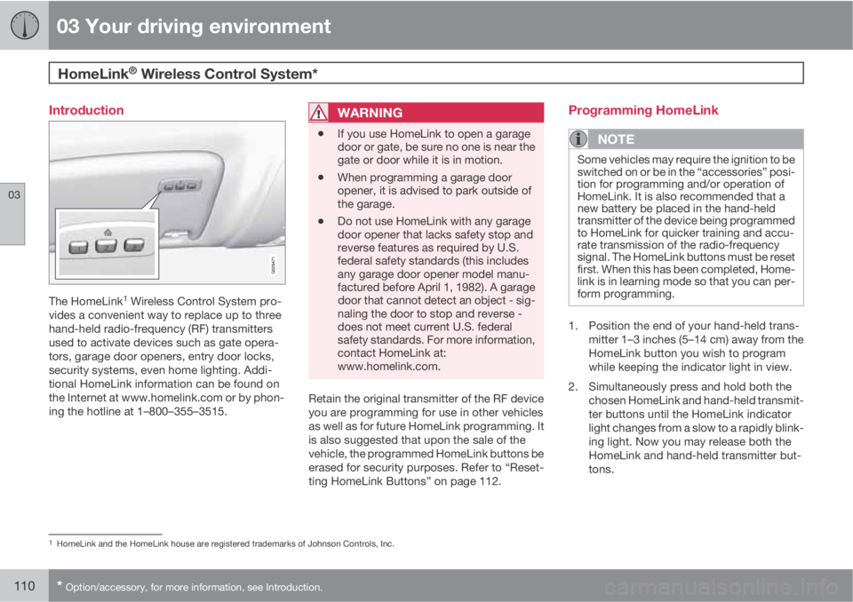
The HomeLink1 Wireless Control System pro-
vides a convenient way to replace up to three
hand-held radio-frequency (RF) transmitters
used to activate devices such as gate opera-
tors, garage door openers, entry door locks,
security systems, even home lighting. Addi-
tional HomeLink information can be found on
the Internet at www.homelink.com or by phon-
ing the hotline at 1–800–355–3515.
WARNING
•If you use HomeLink to open a garage
door or gate, be sure no one is near the
gate or door while it is in motion.
•When programming a garage door
opener, it is advised to park outside of
the garage.
•Do not use HomeLink with any garage
door opener that lacks safety stop and
reverse features as required by U.S.
federal safety standards (this includes
any garage door opener model manu-
factured before April 1, 1982). A garage
door that cannot detect an object - sig-
naling the door to stop and reverse -
does not meet current U.S. federal
safety standards. For more information,
contact HomeLink at:
www.homelink.com.
Retain the original transmitter of the RF device
you are programming for use in other vehicles
as well as for future HomeLink programming. It
is also suggested that upon the sale of the
vehicle, the programmed HomeLink buttons be
erased for security purposes. Refer to “Reset-
ting HomeLink Buttons” on page 112.
Programming HomeLink
NOTE
Some vehicles may require the ignition to be
switched on or be in the “accessories” posi-
tion for programming and/or operation of
HomeLink. It is also recommended that a
new battery be placed in the hand-held
transmitter of the device being programmed
to HomeLink for quicker training and accu-
rate transmission of the radio-frequency
signal. The HomeLink buttons must be reset
first. When this has been completed, Home-
link is in learning mode so that you can per-
form programming.
1. Position the end of your hand-held trans-
mitter 1–3 inches (5–14 cm) away from the
HomeLink button you wish to program
while keeping the indicator light in view.
2. Simultaneously press and hold both the
chosen HomeLink and hand-held transmit-
ter buttons until the HomeLink indicator
light changes from a slow to a rapidly blink-
ing light. Now you may release both the
HomeLink and hand-held transmitter but-
tons.
1HomeLink and the HomeLink house are registered trademarks of Johnson Controls, Inc.
Page 113 of 382
03 Your driving environment
HomeLink® Wireless Control System*
03
* Option/accessory, for more information, see Introduction.111
NOTE
Some devices may require you to replace
this Programming Step 2 with procedures
noted in the “Gate Operator / Canadian Pro-
gramming” section. If the HomeLink indica-
tor light does not change to a rapidly blink-
ing light after performing these steps, con-
tact HomeLink at www.homelink.com or by
phoning the hotline at 1–800–355–3515.
3.
Firmly press, hold for five seconds and
release the programmed HomeLink but-
ton up to two separate times to activate the
door. If the door does not activate, press
and hold the just-trained HomeLink button
and observe the indicator light.
•If the indicator light stays on con-
stantly, programming is complete
and your device should activate when
the HomeLink button is pressed and
released.
•If the indicator light blinks rapidly for
two seconds and then turns to a con-
stant light continue with “Program-
ming” steps 4-6 to complete the pro-
gramming of a rolling code equipped
device (most commonly a garage door
opener).
4. At the garage door opener receiver (motor-
head unit) in the garage, locate the “learn”or “smart” button. This can usually be
found where the hanging antenna wire is
attached to the motor-head unit.
5. Firmly press and release the “learn” or
“smart” button. (The name and color of the
button may vary by manufacturer.) There
are 30 seconds to initiate step 6.
6. Return to the vehicle and firmly press, hold
for two seconds and release the pro-
grammed HomeLink button. Repeat the
“press/hold/release” sequence a second
time, and, depending on the brand of the
garage door opener (or other rolling code
equipped device), repeat this sequence a
third time to complete the programming
process.
HomeLink should now activate your rolling
code equipped device.
Gate Operator/Canadian ProgrammingCanadian radio-frequency laws require trans-
mitter signals to “time-out” (or quit) after sev-
eral seconds of transmission – which may not
be long enough for HomeLink to pick up the
signal during programming. Similar to this
Canadian law, some U.S. gate operators are
designed to “time-out” in the same manner.
If you live in Canada or you are having difficul-
ties programming a gate operator or garage
door opener by using the “Programming” pro-cedures, replace “Programming HomeLink”
step 2 with the following:
•Continue to press and hold the HomeLink
button while you press and release -
every two seconds (“cycle”) your hand-
held transmitter until the HomeLink indica-
tor light changes from a slow to a rapidly
blinking light. Now you may release both
the HomeLink and hand-held transmitter
buttons.
Proceed with “Programming” step 3 to com-
plete.
Using HomeLink
To operate, simply press and hold the pro-
grammed HomeLink button until the trained
device begins to operate (this may take several
seconds). Activation will now occur for the
trained device (i.e., garage door opener, gate
operator, security system, entry door lock,
home/office lighting, etc.). For convenience,
the hand-held transmitter of the device may
also be used at any time. In the event that there
are still programming difficulties or questions,
contact HomeLink at: www.homelink.com or
by phoning the hotline at 1–800–355–3515.
Page 115 of 382
03 Your driving environment
Starting the engine
03
* Option/accessory, for more information, see Introduction.113 Start
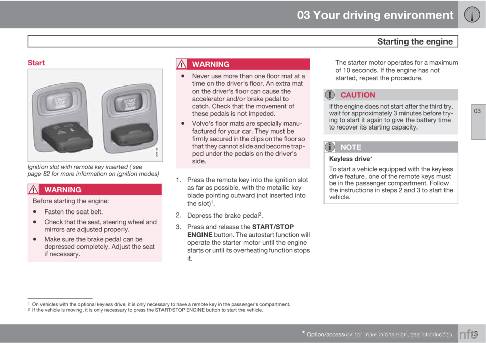
Ignition slot with remote key inserted ( see
page 82 for more information on ignition modes)
WARNING
Before starting the engine:
•Fasten the seat belt.
•Check that the seat, steering wheel and
mirrors are adjusted properly.
•Make sure the brake pedal can be
depressed completely. Adjust the seat
if necessary.
WARNING
•Never use more than one floor mat at a
time on the driver's floor. An extra mat
on the driver's floor can cause the
accelerator and/or brake pedal to
catch. Check that the movement of
these pedals is not impeded.
•Volvo's floor mats are specially manu-
factured for your car. They must be
firmly secured in the clips on the floor so
that they cannot slide and become trap-
ped under the pedals on the driver's
side.
1. Press the remote key into the ignition slot
as far as possible, with the metallic key
blade pointing outward (not inserted into
the slot)
1.
2.
Depress the brake pedal
2.
3.
Press and release the START/STOP
ENGINE button. The autostart function will
operate the starter motor until the engine
starts or until its overheating function stops
it.The starter motor operates for a maximum
of 10 seconds. If the engine has not
started, repeat the procedure.
CAUTION
If the engine does not start after the third try,
wait for approximately 3 minutes before try-
ing to start it again to give the battery time
to recover its starting capacity.
NOTE
Keyless drive*
To start a vehicle equipped with the keyless
drive feature, one of the remote keys must
be in the passenger compartment. Follow
the instructions in steps 2 and 3 to start the
vehicle.
1On vehicles with the optional keyless drive, it is only necessary to have a remote key in the passenger’s compartment.2If the vehicle is moving, it is only necessary to press the START/STOP ENGINE button to start the vehicle.