headlight VOLVO XC70 2014 Owner´s Manual
[x] Cancel search | Manufacturer: VOLVO, Model Year: 2014, Model line: XC70, Model: VOLVO XC70 2014Pages: 394, PDF Size: 11.55 MB
Page 125 of 394

03 Your driving environment
Starting the engine
03
}}
* Option/accessory, for more information, see Introduction.123
Models with a Personal Car
Communicator (PCC) remote key* (seepage 60)
The indicator light for approach lighting will flash several times andthen glow continuously if all of therequirements for ERS have been
met. However, this does not indicate thatERS has started the engine. To check if ERS has started the engine, press the information button (3). If the engine hasstarted, the indicator light for buttons(1) och (4) will illuminate.
Active functionsWhen the engine is started with ERS, the fol- lowing functions are activated: • The climate control system
• The infotainment system.
Deactivated functionsWhen the engine is started with ERS, the fol- lowing functions are deactivated: •Headlights
• Parking lights
• License plate lights
• Windshield wipers
Switching off an engine started with ERS
Any of the following will switch off the engine if it has been started with ERS:
• Pressing the lock button (1) or the unlock button (2) on the remote key
• Unlocking the vehicle
• Opening a door
• Depressing the accelerator or brake pedal
• Moving the gear selector from the
P posi-
tion
• If there are less than approx. 2.5 gallons(10 liters) of fuel in the tank
• More than 15 minutes have elapsed.
If the engine has been started with ERS and switches off, the turn signals will illuminate for3 seconds.
Message in the instrument panel
display
If ERS is interrupted, a text message will bedisplayed in the instrument panel.
Switching off the engine
With the engine running, press the START/
STOP ENGINE button.
If the gear selector is not in the P position or
if the vehicle is moving, press the START/
STOP ENGINE button twice or press and
hold it in until the engine switches off.
Jump starting
G021347
Connecting the jumper cables
Follow these instructions to jump start your vehicle's dead battery or to jump startanother vehicle's dead battery using yourvehicle. If the 12-volt auxiliary battery to beused is in another vehicle, check that thevehicles are not touching to prevent prema-ture completion of a circuit. Be sure to follow
Page 157 of 394

04 Driver support
Adaptive Cruise Control (ACC)*
04
* Option/accessory, for more information, see Introduction.155
•
The gear selected is moved to
P,N or R
• The driver presses the
button to put
ACC in standby mode
The parking brake is applied
automatically
In certain situations, ACC will apply the park- ing brake in order to continue keeping thevehicle at a standstill. This happens if:
• The driver opens the door or takes off his/her seat belt
• DSTC is put in Sport mode (seepage 142)
• ACC has kept the vehicle at a standstillfor more than 2 minutes
• The engine has been switched off
• The brakes have overheated
The radar sensor and its limitations
In addition to being used by ACC, the radar sensor is also used by Distance Alert (seepage 159) and Collision Warning with FullAuto-brake and Pedestrian Detection (seepage 168). This sensor is designed to detectcars or larger vehicles driving in the samedirection as your vehicle, in the same lane.
WARNING
• If there is visible damage to the front grille or you suspect that the radarsensor may be damaged in any way,contact a trained and qualified Volvoservice technician as soon as possible.The radar sensor may only functionpartially (or not at all) if it is damagedor is not securely fastened in place.
• Accessories or other objects, such asextra headlights, must not be installedin front of the grille.
• Modification of the radar sensor couldmake its use illegal.
The radar sensor's capacity to detect vehi- cles ahead is impeded:
• if the radar sensor is obstructed and can- not detect other vehicles, for example inheavy rain, or if snow or other objects areobscuring the radar sensor.
NOTE
Keep the area in front of the radar sensor clean.
• if the speed of vehicles ahead is signifi- cantly different from your own speed.
Situations where ACC may not function optimally
WARNING
•The radar sensor has a limited field of vision. In some situations it may detecta vehicle later than expected or notdetect other vehicles at all.
• If ACC is not functioning properly,cruise control will also be disabled.
Page 186 of 394

04 Driver support
Park assist*
04
184* Option/accessory, for more information, see Introduction.
NOTE
• Rear park assist is deactivated auto- matically when towing a trailer if Volvogenuine trailer wiring is used. If a non-Volvo trailer hitch is being used, it maybe necessary to switch off the systemmanually, see page 182.
• The system will not detect highobjects, such as a loading dock, etc.
• Objects such as chains, thin shinypoles or low objects may temporarilynot be detected by the system. Thismay result in the pulsing tone unex-pectedly stopping instead of changingto a constant tone as the vehicleapproaches the object. In such cases,use caution when backing up or stopthe vehicle to help avoid damage.
Front park assist
G021424
The distance monitored in front of the vehicle is approximately 2.5 ft (0.8 m). The audiblesignal comes from the audio system's frontspeakers. It may not be possible to combine auxiliary headlights and front park assist since theselights could trigger the system's sensors.
NOTE
Front park assist is deactivated when the parking brake is applied and or when thegear selector is in the
P position.
Faults in the system
If the information symbol illuminates andPark assist syst Service required is shown
on the information display, this indicates that the system is not functioning properly andhas been disengaged. Consult a trained andqualified Volvo service technician.
CAUTION
In certain circumstances, the park assist system may give unexpected warning sig-nals that can be caused by external soundsources that use the same ultrasound fre-quencies as the system. This may includesuch things as the horns of other vehicles,wet tires on asphalt, pneumatic brakes,motorcycle exhaust pipes, etc. This doesnot indicate a fault in the system.
Page 193 of 394
04 Driver support
Blind Spot Information System (BLIS)*
04
* Option/accessory, for more information, see Introduction.191
When does BLIS function
The system functions when your vehicle is moving at speeds above 6 mph (10 km/h).
When you pass another vehicle:The system reacts when you pass another vehicle at a speed of up to 6 mph (10 km/h)faster than that vehicle.
When you are passed by another
vehicle:
The system reacts if your vehicle is passed by another vehicle at a speed of up to 43 mph(70 km/h) faster than your vehicle.
WARNING
• BLIS does not function in sharp curves.
• BLIS does not function when yourvehicle is backing up.
• If you are towing a wide trailer, thismay prevent the BLIS cameras fromdetecting other vehicles in adjacentlanes.
How BLIS functions in daylight and darkness
DaylightBLIS reacts to the
shape of surrounding vehi-
cles. The system is designed to help detect motor vehicles such as cars, trucks, buses, motorcycles, etc.
DarknessBLIS reacts to the
headlights of surrounding
vehicles. In order to be detected by BLIS, a vehicle in the blind area must have its head-lights on. This means, for example, that thesystem will not detect a trailer without head-lights that is being towed behind a car ortruck.
WARNING
• BLIS does not react to cyclists or mopeds.
• BLIS does not react to vehicles thatare standing still.
• The BLIS cameras have the same limi-tation as the human eye. In otherwords, their "vision is impaired" byadverse weather conditions such asheavy snowfall, intense light directlyinto the camera, dense fog, etc.
LimitationsIn certain situations, the BLIS indicator light(s) may illuminate even when there are no othervehicles in the area monitored by the system.
NOTE
If the BLIS indicator lights illuminate occa- sionally even when there are no other vehi-cles in the blind area, this does not indi-cate a fault in the system. In the event of a fault,
Blind spot syst.
Service required will be displayed.
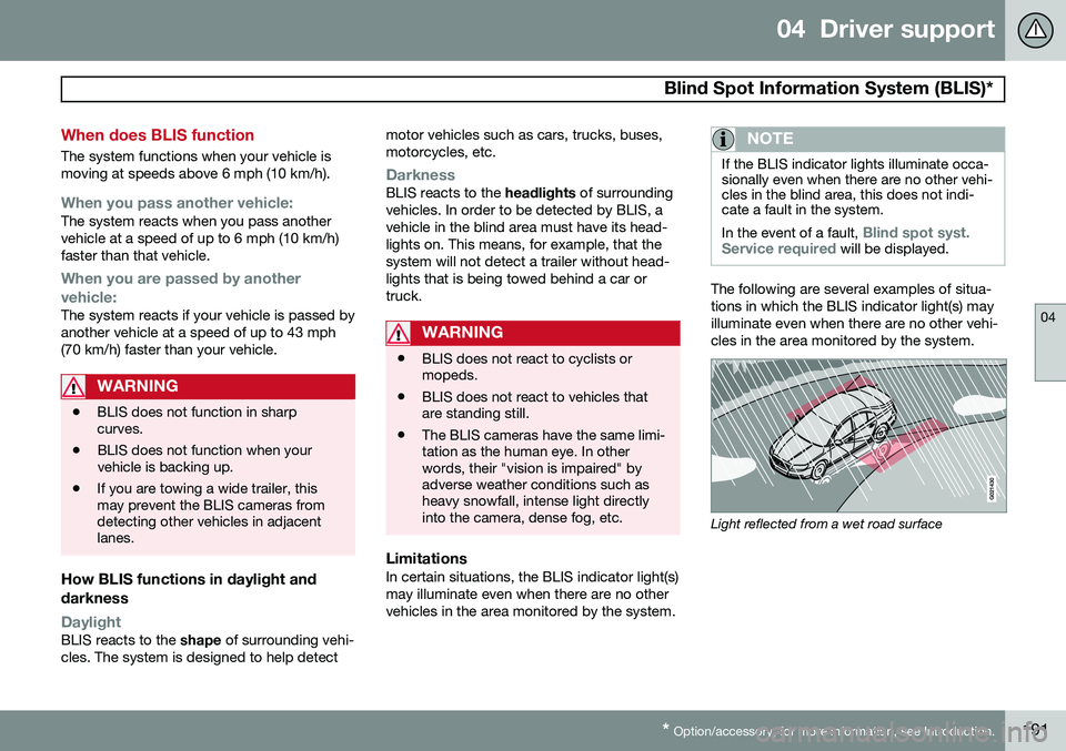
The following are several examples of situa- tions in which the BLIS indicator light(s) mayilluminate even when there are no other vehi-cles in the area monitored by the system.
Light reflected from a wet road surface
Page 335 of 394

09 Maintenance and specifications
Maintaining your car09
333
Owner maintenance
Periodic maintenance requirements and inter- vals are described in your vehicle's Warrantyand Service Records Information booklet. The following points can be carried out between the normally scheduled maintenanceservices.
Each time the car is refueled:
•Check the engine oil level.
• Clean the windshield, windshield wipers, headlights, and taillights.
Monthly:
• Check cold tire pressure in all tires.Inspect the tires for wear.
• Check that engine coolant and other fluidlevels are between the indicated "min"and "max" markings.
• Clean interior glass surfaces with a glasscleaner and soft paper towels.
• Wipe driver information displays with asoft cloth.
• Visually inspect battery terminals for cor-rosion. Corrosion may indicate a looseterminal connector, or a battery near theend of its useful service life. Consult yourVolvo retailer for additional information.
As needed:Wash the car, including the undercarriage, to reduce wear that can be caused by a buildupof dirt, and corrosion that can be caused bysalt residues. Clean leaves and twigs from air intake vents at the base of the windshield, and from otherplaces where they may collect.
NOTE
Complete service information for qualified technicians is available online for purchaseor subscription at www.volvotechinfo.com.
Hoisting the vehicle
If a garage jack is used to lift the vehicle, the two jack attachments points should be used. They are specially reinforced to bear theweight of the vehicle. A garage jack can alsobe placed under the front of the engine sup-port frame. Take care not to damage thesplash guard under the engine. Ensure thatthe jack is positioned so that the vehicle can-not slide off it. Always use axle stands or sim-ilar structures. If a two-post hoist is used to lift the vehicle, the front and rear lift arm pads should becentered under the reinforced lift plates onthe inboard edge of the sill rail (see illustra-tion).
Emission inspection readiness
What is an Onboard Diagnostic System
(OBD II)?
OBD II is part of your vehicle's computerized engine management system. It stores diag-nostic information about your vehicle's emis-sion controls. It can light the Check Enginelight (MIL) if it detects an emission control"fault." A "fault" is a component or systemthat is not performing within an expectedrange. A fault may be permanent or tempo-rary. OBD II will store a message about anyfault.
Page 342 of 394
09 Maintenance and specifications
Replacing bulbs 09
340* Option/accessory, for more information, see Introduction.
Introduction
All bulb specifications are listed on page 345. The following bulbs should only be replacedby a trained and qualified Volvo service tech-nician:
• Active Bending Lights
• Front parking lights
• Daytime running lights
• Turn signals in the door mirrors
• Approach lighting in the door mirrors
• Interior lighting
• Glove compartment lighting
• Brake lights
• Rear parking lights
• Rear side marker lights
• Back-up lights
• Rear fog light
• LED bulbsNOTE
•For information regarding any bulbs not mentioned in this section, pleasecontact your Volvo retailer or a trainedand authorized Volvo service techni-cian.
• Always switch off the ignition beforestarting to replace a bulb.
• If an error message remains in the dis-play after a faulty bulb has beenreplaced, contact an authorized Volvoworkshop.
• Condensation may form temporarily onthe inside of the lenses of exteriorlights such as headlights, fog lights, ortaillights. This is normal and the lightsare designed to withstand moisture.Normally, condensation will dissipateafter the lights have been on for ashort time.
• The optional Active Bending Lightbulbs contain trace amounts of mer-cury. These bulbs should always bedisposed of by a trained and qualifiedVolvo service technician.
CAUTION
Never touch the glass of bulbs with your fingers. Grease and oils from your fingersvaporize in the heat and will leave adeposit on the reflector, which will damageit.
WARNING
•The engine should not be running when changing bulbs.
• If the engine has been running justprior to replacing bulbs in the head-light housing, please keep in mind thatcomponents in the engine compart-ment will be hot.
WARNING
•Active Bending Lights* – due to the high voltage used by these headlights,these bulbs should only be replacedby a trained and qualified Volvo serv-ice technician.
• Turn off the lights and remove theremote key from the ignition beforechanging any bulbs.
Page 343 of 394
09 Maintenance and specifications
Replacing bulbs09
341
Headlight housing
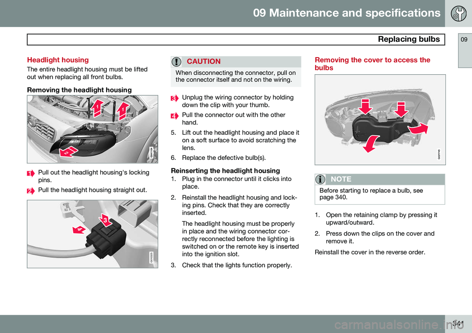
The entire headlight housing must be lifted out when replacing all front bulbs.
Removing the headlight housing
Pull out the headlight housing's locking pins.
Pull the headlight housing straight out.
G010325
CAUTION
When disconnecting the connector, pull on the connector itself and not on the wiring.
Unplug the wiring connector by holding down the clip with your thumb.
Pull the connector out with the other hand.
5. Lift out the headlight housing and place it on a soft surface to avoid scratching thelens.
6. Replace the defective bulb(s).
Reinserting the headlight housing1. Plug in the connector until it clicks into place.
2. Reinstall the headlight housing and lock- ing pins. Check that they are correctlyinserted. The headlight housing must be properly in place and the wiring connector cor-rectly reconnected before the lighting isswitched on or the remote key is insertedinto the ignition slot.
3. Check that the lights function properly.
Removing the cover to access the bulbs
G021745
NOTE
Before starting to replace a bulb, see page 340.
1. Open the retaining clamp by pressing it upward/outward.
2. Press down the clips on the cover and remove it.
Reinstall the cover in the reverse order.
Page 344 of 394
09 Maintenance and specifications
Replacing bulbs 09
342
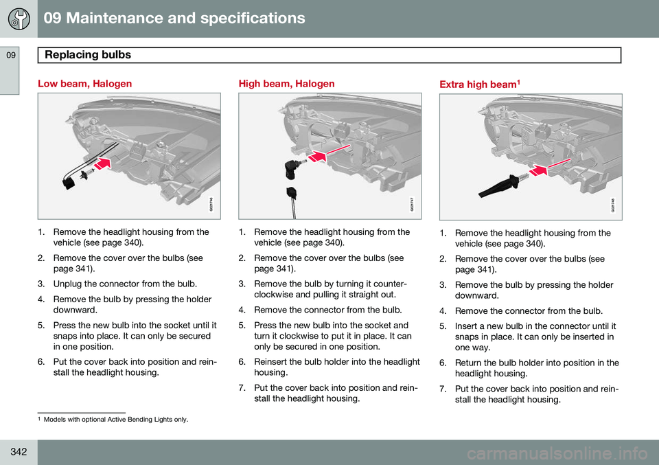
Low beam, Halogen
G021746
1. Remove the headlight housing from thevehicle (see page 340).
2. Remove the cover over the bulbs (see page 341).
3. Unplug the connector from the bulb.
4. Remove the bulb by pressing the holder downward.
5. Press the new bulb into the socket until it snaps into place. It can only be secured in one position.
6. Put the cover back into position and rein- stall the headlight housing.
High beam, Halogen
G021747
1. Remove the headlight housing from thevehicle (see page 340).
2. Remove the cover over the bulbs (see page 341).
3. Remove the bulb by turning it counter- clockwise and pulling it straight out.
4. Remove the connector from the bulb.
5. Press the new bulb into the socket and turn it clockwise to put it in place. It can only be secured in one position.
6. Reinsert the bulb holder into the headlight housing.
7. Put the cover back into position and rein- stall the headlight housing.
Extra high beam 1
G021748
1. Remove the headlight housing from the
vehicle (see page 340).
2. Remove the cover over the bulbs (see page 341).
3. Remove the bulb by pressing the holder downward.
4. Remove the connector from the bulb.
5. Insert a new bulb in the connector until it snaps in place. It can only be inserted in one way.
6. Return the bulb holder into position in the headlight housing.
7. Put the cover back into position and rein- stall the headlight housing.
1Models with optional Active Bending Lights only.
Page 345 of 394
09 Maintenance and specifications
Replacing bulbs09
343
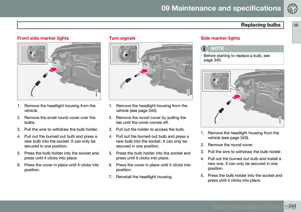
Front side marker lights
G021751
1. Remove the headlight housing from thevehicle.
2. Remove the small round cover over the bulbs.
3. Pull the wire to withdraw the bulb holder.
4. Pull out the burned out bulb and press a new bulb into the socket. It can only be secured in one position.
5. Press the bulb holder into the socket and press until it clicks into place.
6. Press the cover in place until it clicks into position.
Turn signals
G021750
1. Remove the headlight housing from thevehicle (see page 340).
2. Remove the round cover by pulling the tab until the cover comes off.
3. Pull out the holder to access the bulb.
4. Pull out the burned out bulb and press a new bulb into the socket. It can only be secured in one position.
5. Press the bulb holder into the socket and press until it clicks into place.
6. Press the cover in place until it clicks into position.
7. Reinstall the headlight housing.
Side marker lights
NOTE
Before starting to replace a bulb, see page 340.
G021751
1. Remove the headlight housing from the vehicle (see page 340).
2. Remove the round cover.
3. Pull the wire to withdraw the bulb holder.
4. Pull out the burned out bulb and install a new one. It can only be secured in one position.
5. Press the bulb holder into the socket and press until it clicks into place.
Page 350 of 394
09 Maintenance and specifications
Wiper blades and washer fluid 09
348
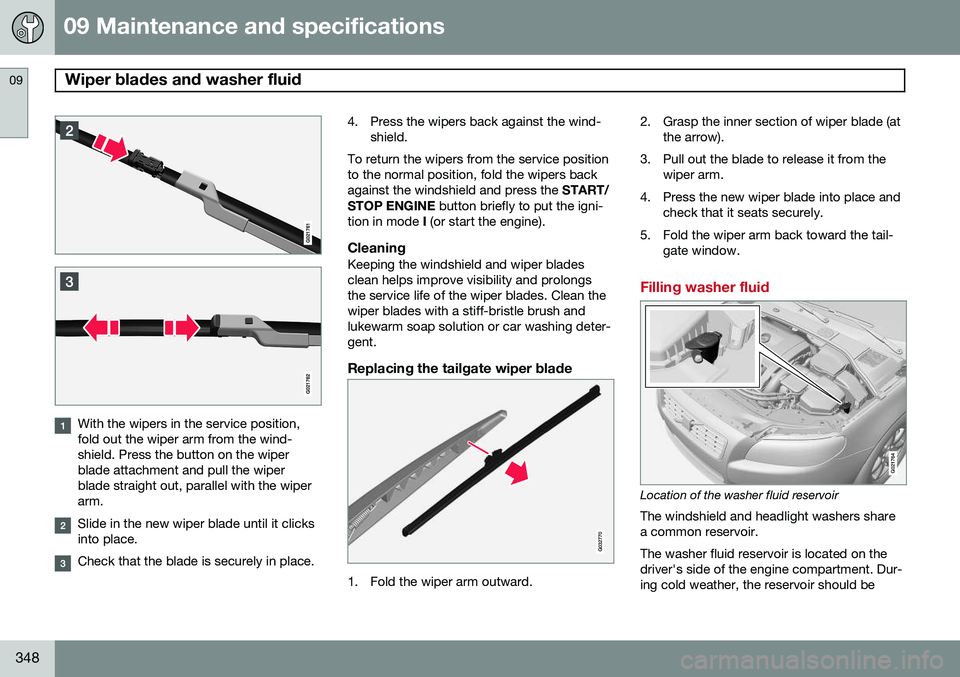
With the wipers in the service position, fold out the wiper arm from the wind-shield. Press the button on the wiperblade attachment and pull the wiperblade straight out, parallel with the wiperarm.
Slide in the new wiper blade until it clicks into place.
Check that the blade is securely in place.4. Press the wipers back against the wind-
shield.
To return the wipers from the service position to the normal position, fold the wipers backagainst the windshield and press the START/
STOP ENGINE button briefly to put the igni-
tion in mode I (or start the engine).
CleaningKeeping the windshield and wiper bladesclean helps improve visibility and prolongsthe service life of the wiper blades. Clean thewiper blades with a stiff-bristle brush andlukewarm soap solution or car washing deter-gent.
Replacing the tailgate wiper blade
G032770
1. Fold the wiper arm outward. 2. Grasp the inner section of wiper blade (at
the arrow).
3. Pull out the blade to release it from the wiper arm.
4. Press the new wiper blade into place and check that it seats securely.
5. Fold the wiper arm back toward the tail- gate window.
Filling washer fluid
G021764
Location of the washer fluid reservoir
The windshield and headlight washers share a common reservoir. The washer fluid reservoir is located on the driver's side of the engine compartment. Dur-ing cold weather, the reservoir should be