tow VOLVO XC70 2014 Owner´s Manual
[x] Cancel search | Manufacturer: VOLVO, Model Year: 2014, Model line: XC70, Model: VOLVO XC70 2014Pages: 394, PDF Size: 11.55 MB
Page 170 of 394
04 Driver support
Collision warning with Full Auto-brake and Pedestrian Detection*
04
168* Option/accessory, for more information, see Introduction.
Introduction
Collision Warning with Full Auto-brake and Pedestrian Detection is designed to assist thedriver if there is a risk of a collision with apedestrian, a vehicle ahead that is at a stand-still or one that is moving in the same direc-tion as your vehicle. Collision Warning consists of the following three functions:
• Collision Warning
warns the driver of a
potential collision situation.
• Brake Support
helps the driver brake
efficiently in a critical situation.
• Auto-brake
brakes the vehicle automati-
cally if a collision with a pedestrian or another vehicle cannot be avoided andthe driver does not apply the brakes intime or steer around the person/vehicle.Auto-brake can help prevent a collision orreduce the speed at which a collisionoccurs.
Since Collision Warning with Full Auto-brake and Pedestrian Detection is activated in cir-cumstances where the driver should havebegun braking much sooner, the system willnot be able to assist the driver in all situa-tions. This system is designed to activate as late as possible to help avoid unnecessary interven-tion. The system should not be used in such a waythat the driver changes his/her way of operat-ing the vehicle. If the driver relies entirely onthe system, the chances of an accident even-tually occurring increase considerably. The Collision Warning and City Safety™ sys- tems supplement each other. See page 162for detailed information about City Safety™.
WARNING
No automatic system can be guaranteed to function 100% correctly in all situations.For that reason, never test the Auto-brakesystem by driving toward a person orobject. This could result in serious injury ordeath.
WARNING
•
Collision Warning does not work in all driving, traffic, weather and road con-ditions. It does not react to vehiclesnot traveling in the same direction asyour vehicle.
• Collision Warning does not react toanimals.
• Warnings are only provided when therisk of collision is high. The "Function"section provides information aboutlimitations that the driver must beaware of before using Collision Warn-ing.
• Collision Warning will not provide awarning or brake the vehicle forpedestrians at speeds above 50 mph(80 km/h).
Page 185 of 394

04 Driver support
Park assist*
04
* Option/accessory, for more information, see Introduction.183
Signals from the park assist system
View in the display (warning for objects front left/ right rear)
Visual indicatorThe audio system’s display gives an overview of the vehicle’s position in relation to adetected object. The marked sectors in the display indicate that one or more of the sensors has detectedan object. The closer the car symbol comesto a sector, the closer the vehicle is to theobject. If the infotainment system is switched off, the park assist system will not be able to providea visual indicator. An audible signal will stillbe provided.
Audible signalThe Park Assist system uses an intermittenttone that pulses faster as you come close toan object, and becomes constant when youare within approximately 1 ft (30 cm) of anobject in front of or behind the vehicle. Ifthere are objects within this distance bothbehind and in front of the vehicle, the tonealternates between front and rear speakers.
NOTE
The level of the audible signal can be low- ered/raised with the infotainment volumecontrol. The level can also be set in the MYCAR menu system. See page 199 for adescription of the menu system.
If the volume of another source from the audio system is high, this will be automati-cally lowered.
Rear park assist
G017833
The distance monitored behind the vehicle is approximately 5 ft (1.5 m). The audible signalcomes from the rear speakers. The system must be deactivated when towing a trailer, carrying bicycles in a rear-mountedcarrier, etc, which could trigger the rear parkassist system's sensors.
Page 186 of 394

04 Driver support
Park assist*
04
184* Option/accessory, for more information, see Introduction.
NOTE
• Rear park assist is deactivated auto- matically when towing a trailer if Volvogenuine trailer wiring is used. If a non-Volvo trailer hitch is being used, it maybe necessary to switch off the systemmanually, see page 182.
• The system will not detect highobjects, such as a loading dock, etc.
• Objects such as chains, thin shinypoles or low objects may temporarilynot be detected by the system. Thismay result in the pulsing tone unex-pectedly stopping instead of changingto a constant tone as the vehicleapproaches the object. In such cases,use caution when backing up or stopthe vehicle to help avoid damage.
Front park assist
G021424
The distance monitored in front of the vehicle is approximately 2.5 ft (0.8 m). The audiblesignal comes from the audio system's frontspeakers. It may not be possible to combine auxiliary headlights and front park assist since theselights could trigger the system's sensors.
NOTE
Front park assist is deactivated when the parking brake is applied and or when thegear selector is in the
P position.
Faults in the system
If the information symbol illuminates andPark assist syst Service required is shown
on the information display, this indicates that the system is not functioning properly andhas been disengaged. Consult a trained andqualified Volvo service technician.
CAUTION
In certain circumstances, the park assist system may give unexpected warning sig-nals that can be caused by external soundsources that use the same ultrasound fre-quencies as the system. This may includesuch things as the horns of other vehicles,wet tires on asphalt, pneumatic brakes,motorcycle exhaust pipes, etc. This doesnot indicate a fault in the system.
Page 193 of 394
04 Driver support
Blind Spot Information System (BLIS)*
04
* Option/accessory, for more information, see Introduction.191
When does BLIS function
The system functions when your vehicle is moving at speeds above 6 mph (10 km/h).
When you pass another vehicle:The system reacts when you pass another vehicle at a speed of up to 6 mph (10 km/h)faster than that vehicle.
When you are passed by another
vehicle:
The system reacts if your vehicle is passed by another vehicle at a speed of up to 43 mph(70 km/h) faster than your vehicle.
WARNING
• BLIS does not function in sharp curves.
• BLIS does not function when yourvehicle is backing up.
• If you are towing a wide trailer, thismay prevent the BLIS cameras fromdetecting other vehicles in adjacentlanes.
How BLIS functions in daylight and darkness
DaylightBLIS reacts to the
shape of surrounding vehi-
cles. The system is designed to help detect motor vehicles such as cars, trucks, buses, motorcycles, etc.
DarknessBLIS reacts to the
headlights of surrounding
vehicles. In order to be detected by BLIS, a vehicle in the blind area must have its head-lights on. This means, for example, that thesystem will not detect a trailer without head-lights that is being towed behind a car ortruck.
WARNING
• BLIS does not react to cyclists or mopeds.
• BLIS does not react to vehicles thatare standing still.
• The BLIS cameras have the same limi-tation as the human eye. In otherwords, their "vision is impaired" byadverse weather conditions such asheavy snowfall, intense light directlyinto the camera, dense fog, etc.
LimitationsIn certain situations, the BLIS indicator light(s) may illuminate even when there are no othervehicles in the area monitored by the system.
NOTE
If the BLIS indicator lights illuminate occa- sionally even when there are no other vehi-cles in the blind area, this does not indi-cate a fault in the system. In the event of a fault,
Blind spot syst.
Service required will be displayed.
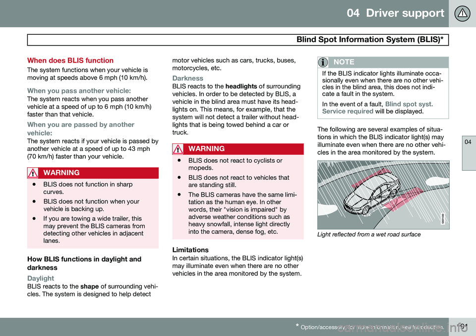
The following are several examples of situa- tions in which the BLIS indicator light(s) mayilluminate even when there are no other vehi-cles in the area monitored by the system.
Light reflected from a wet road surface
Page 209 of 394
05 Comfort and driving pleasure
Climate system
05
}}
207
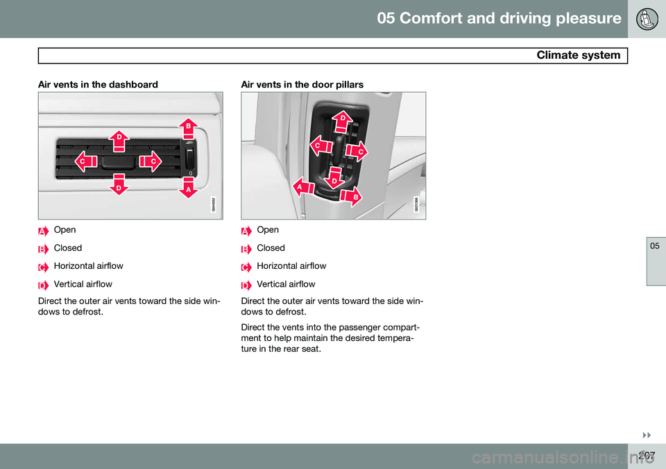
Air vents in the dashboard
Open
Closed
Horizontal airflow
Vertical airflow
Direct the outer air vents toward the side win- dows to defrost.
Air vents in the door pillars
G021368
Open
Closed
Horizontal airflow
Vertical airflow
Direct the outer air vents toward the side win- dows to defrost. Direct the vents into the passenger compart- ment to help maintain the desired tempera-ture in the rear seat.
Page 274 of 394
272
Driving recommendations..................................................................... 274 Refueling............................................................................................... 278Loading................................................................................................. 283Cargo area ........................................................................................... 289Towing a trailer...................................................................................... 293
Emergency towing................................................................................ 296
Page 277 of 394

07 During your trip
Driving recommendations
07
275
Handling, roadholdingVehicle load, tire design and inflation pres- sure all affect vehicle handling. Therefore,check that the tires are inflated to the recom-mended pressure according to the vehicleload. See the "Tire pressure" section. Loadsshould be distributed so that capacity weightor maximum permissible axle loads are notexceeded.
Driving through water
•The vehicle can be driven through water up to a depth of approximately 10 in.(25 cm), at a maximum speed of 6 mph(10 km/h).
• Take particular care when driving throughflowing water.
• Clean the electrical connections for trailerwiring after driving in mud or water.
• When driving through water, maintain lowspeed and do not stop in the water.
WARNING
•Avoid driving through standing or rushing water. Doing so can be dan-gerous and it may also be difficult todetermine the actual depth of thewater.
• If water cannot be avoided, after driv-ing through the water, press lightly onthe brake pedal to ensure that thebrakes are functioning normally. Wateror mud can make the brake liningsslippery, resulting in delayed brakingeffect.
CAUTION
• Engine damage will occur if water is drawn into the air cleaner.
• If the vehicle is driven through waterdeeper than 10 in (25 cm), water mayenter the differential and the transmis-sion. This reduces the oil's lubricatingcapacity and may shorten the servicelife of these components.
• Do not allow the vehicle to stand inwater up to the door sills longer thanabsolutely necessary. This could resultin electrical malfunctions.
• If the engine has been stopped whilethe vehicle is in water, do not attemptto restart it. Have the vehicle towedout of the water.
Engine and cooling systemUnder special conditions, for example when driving in hilly terrain, extreme heat or withheavy loads, there is a risk that the engineand cooling system will overheat. Proceed asfollows to avoid overheating the engine. •
Maintain a low speed when driving with a trailer up long, steep hills.
• Do not turn the engine off immediatelywhen stopping after a hard drive.
Page 281 of 394
07 During your trip
Refueling
07
279
Octane rating
Minimum octane
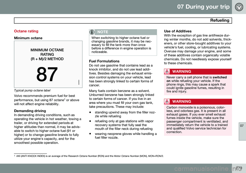
G028920
Typical pump octane labelVolvo recommends premium fuel for best performance, but using 87 octane 1
or above
will not affect engine reliability.
Demanding drivingIn demanding driving conditions, such as operating the vehicle in hot weather, towing atrailer, or driving for extended periods athigher altitudes than normal, it may be advis-able to switch to higher octane fuel (91 orhigher) or to change gasoline brands to fullyutilize your engine's capacity, and for thesmoothest possible operation.
NOTE
When switching to higher octane fuel or changing gasoline brands, it may be nec-essary to fill the tank more than oncebefore a difference in engine operation isnoticeable.
Fuel FormulationsDo not use gasoline that contains lead as a knock inhibitor, and do not use lead addi-tives. Besides damaging the exhaust emis-sion control systems on your vehicle, leadhas been strongly linked to certain forms ofcancer. Many fuels contain benzene as a solvent. Unburned benzene has been strongly linkedto certain forms of cancer. If you live in anarea where you must fill your own gas tank,take precautions. These may include:
• standing upwind away from the filler noz- zle while refueling
• refueling only at gas stations with vaporrecovery systems that fully seal themouth of the filler neck during refueling
• wearing neoprene gloves while handling afuel filler nozzle.
Use of AdditivesWith the exception of gas line antifreeze dur- ing winter months, do not add solvents, thick-eners, or other store-bought additives to yourvehicle's fuel, cooling, or lubricating systems.Overuse may damage your engine, and someof these additives contain organically volatilechemicals. Do not needlessly expose yourselfto these chemicals.
WARNING
Never carry a cell phone that is
switched
on while refueling your vehicle. If the
phone rings, this may cause a spark that could ignite gasoline fumes, resulting infire and injury.
WARNING
Carbon monoxide is a poisonous, color- less, and odorless gas. It is present in allexhaust gases. If you ever smell exhaustfumes inside the vehicle, make sure thepassenger compartment is ventilated, andimmediately return the vehicle to a trainedand qualified Volvo service technician forcorrection.
1 AKI (ANTI KNOCK INDEX) is an average of the Research Octane Number (RON) and the Motor Octane Number (MON), MON+RON/2.
Page 288 of 394
07 During your trip
Loading
07
286
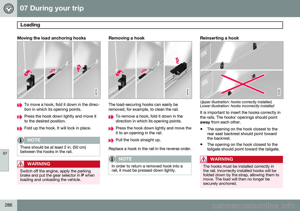
Moving the load anchoring hooks
G017742
To move a hook, fold it down in the direc- tion in which its opening points.
Press the hook down lightly and move it to the desired position.
Fold up the hook. It will lock in place.
NOTE
There should be at least 2 in. (50 cm) between the hooks in the rail.
WARNING
Switch off the engine, apply the parking brake and put the gear selector in P when
loading and unloading the vehicle.
Removing a hook
G018134
The load-securing hooks can easily be removed, for example, to clean the rail.
To remove a hook, fold it down in the direction in which its opening points.
Press the hook down lightly and move the it to an opening in the rail.
Pull the hook straight up.
Replace a hook in the rail in the reverse order.
NOTE
In order to return a removed hook into a rail, it must be pressed down lightly.
Reinserting a hook
G019581
Upper illustration: hooks correctly installed, Lower illustration: hooks incorrectly installed
It is important to insert the hooks correctly in the rails. The hooks' openings should pointaway from each other.
• The opening on the hook closest to the rear seat backrest should point towardthe backrest.
• The opening on the hook closest to thetailgate should point toward the tailgate.
WARNING
The hooks must be installed correctly in the rail. Incorrectly installed hooks will befolded down by the strap, allowing them tomove. The load will then no longer besecurely anchored.
Page 291 of 394
07 During your trip
Cargo area
07
* Option/accessory, for more information, see Introduction.289
Steel cargo grid*
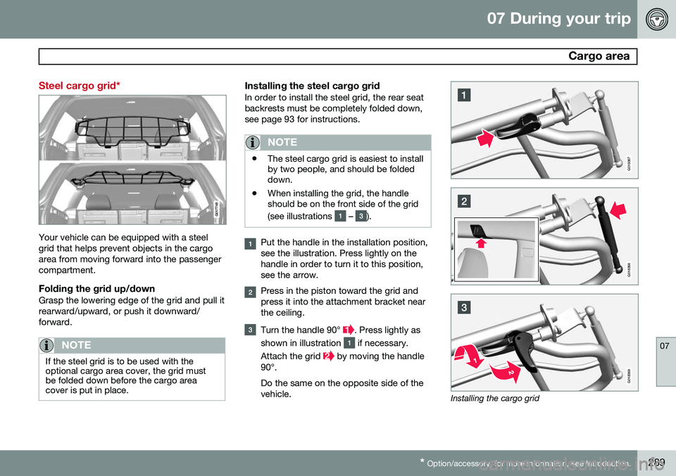
G017748
Your vehicle can be equipped with a steel grid that helps prevent objects in the cargoarea from moving forward into the passengercompartment.
Folding the grid up/downGrasp the lowering edge of the grid and pull itrearward/upward, or push it downward/forward.
NOTE
If the steel grid is to be used with the optional cargo area cover, the grid mustbe folded down before the cargo areacover is put in place.
Installing the steel cargo gridIn order to install the steel grid, the rear seat backrests must be completely folded down,see page 93 for instructions.
NOTE
• The steel cargo grid is easiest to install by two people, and should be foldeddown.
• When installing the grid, the handleshould be on the front side of the grid (see illustrations
– ).
Put the handle in the installation position, see the illustration. Press lightly on thehandle in order to turn it to this position,see the arrow.
Press in the piston toward the grid and press it into the attachment bracket nearthe ceiling.
Turn the handle 90° . Press lightly as
shown in illustration
if necessary.
Attach the grid
by moving the handle
90°. Do the same on the opposite side of the vehicle.
G018367
G018368
G018369
Installing the cargo grid