brake light VOLVO XC70 2014 Owner´s Manual
[x] Cancel search | Manufacturer: VOLVO, Model Year: 2014, Model line: XC70, Model: VOLVO XC70 2014Pages: 394, PDF Size: 11.55 MB
Page 5 of 394
Contents
* Option/accessory, for more information, see Introduction.3
03
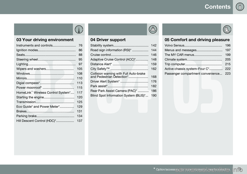
03 Your driving environment
Instruments and controls.......................... 76
Ignition modes.......................................... 86
Seats......................................................... 88
Steering wheel.......................................... 95
Lighting..................................................... 97
Wipers and washers............................... 105
Windows................................................. 108
Mirrors..................................................... 110
Digial compass*...................................... 113
Power moonroof* ................................... 115 HomeLink ®
Wireless Control System*.... 117
Starting the engine.................................. 120
Transmission........................................... 125
Eco Guide* and Power Meter*................ 129
Brakes..................................................... 131
Parking brake.......................................... 134
Hill Descent Control (HDC)*.................... 137
04
04 Driver support
Stability system....................................... 142
Road sign information (RSI)* .................. 144
Cruise control.......................................... 146
Adaptive Cruise Control (ACC)*.............. 148
Distance Alert* ....................................... 159
City Safety™ .......................................... 162Collision warning with Full Auto-brake
and Pedestrian Detection*...................... 168
Driver Alert System* ............................... 176
Park assist*............................................. 182
Rear Park Assist Camera (PAC)* ............ 186
Blind Spot Information System (BLIS)*... 190
05
05 Comfort and driving pleasure
Volvo Sensus.......................................... 196
Menus and messages............................. 197
The MY CAR menus............................... 199
Climate system....................................... 205
Trip computer......................................... 215
Active chassis system–Four C*............... 222
Passenger compartment convenience... 223
Page 11 of 394
Introduction
Important information
9
ShiftlockWhen your vehicle is parked, the gear selec- tor is locked in the P (Park) position. To
release the selector from this position, theignition must be in mode II (see page 86) orthe engine must be running. Depress thebrake pedal, press the button on the frontside of the gear selector and move the selec-tor from P (Park).
Anti-lock Brake System (ABS)The ABS system performs a brief self-diag-nostic test when the engine has been startedand driver releases the brake pedal. Anotherautomatic test may be performed when thevehicle first reaches a speed of approximately6 mph (10 km/h). The brake pedal will pulsateseveral times and a sound may be audiblefrom the ABS control module. This is normal.
Fuel filler doorPress the button on the light switch panel(see the illustration on page 280) when thevehicle is at a standstill to unlock the fuel fillerdoor. It will relock when closed and there willbe an audible click.
Points to keep in mind
• Do not export your Volvo to another country before investigating that coun-try's applicable safety and exhaust emis-sion requirements. In some cases it maybe difficult or impossible to comply with these requirements. Modifications to theemission control system(s) may renderyour Volvo not certifiable for legal opera-tion in the U.S., Canada and other coun-tries.
• All information, illustrations and specifica-tions contained in this manual are basedon the latest product information availa-ble at the time of publication. Please notethat some vehicles may be equipped dif-ferently, depending on special legalrequirements. Optional equipment descri-bed in this manual may not be available inall markets.
• Some of the illustrations shown aregeneric and may not depict the exactmodel for which this manual is intended.
• Volvo reserves the right to make modelchanges at any time, or to change speci-fications or design without notice andwithout incurring obligation.
Crash event data
This vehicle is equipped with an event data recorder (EDR). The main purpose of an EDRis to record, in certain crash or near crash-likesituations, such as an air bag deployment orhitting a road obstacle, data that will assist inunderstanding how a vehicle's systems per-formed. The EDR is designed to record datarelated to vehicle dynamics and safety sys- tems for a short period of time, typically 30seconds or less. The EDR in this vehicle isdesigned to record such data as:
• How various systems in your vehicle were operating;
• Whether or not the driver and passengersafety belts were buckled/fastened;
• How far (if at all) the driver was depress-ing the accelerator and/or brake pedal;and,
• How fast the vehicle was traveling.
These data can help provide a better under- standing of the circumstances in whichcrashes and injuries occur.
NOTE
EDR data are recorded by your vehicle only if a non-trivial crash situation occurs;no data are recorded by the EDR undernormal driving conditions and no personaldata (e.g., name, gender, age, and crashlocation) are recorded. However, otherparties, such as law enforcement, couldcombine the EDR data with the type ofpersonally identifying data routinelyacquired during a crash investigation.
To read data recorded by an EDR, special equipment is required, and access to thevehicle or the EDR is needed. In addition to
Page 14 of 394
Introduction
Environment
12
Volvo and the environment
Volvo is committed to the well being of its customers. As a natural part of this commit-ment, we care about the environment inwhich we all live. Caring for the environmentmeans an everyday involvement in reducingour environmental impact. Volvo's environ-mental activities are based on a holistic view,which means we consider the overall environ-mental impact of a product throughout itscomplete life cycle. In this context, design,production, product use, and recycling are allimportant considerations. In production,Volvo has partly or completely phased outseveral chemicals including CFCs, lead chro-mates, asbestos, and cadmium; and reducedthe number of chemicals used in ourplants 50% since 1991. Volvo was the first in the world to introduce into production a three-way catalytic con-verter with a Lambda sond, now called theheated oxygen sensor, in 1976. The currentversion of this highly efficient system reducesemissions of harmful substances (CO, HC,NOx) from the exhaust pipe by approximately95 – 99% and the search to eliminate theremaining emissions continues. Volvo is theonly automobile manufacturer to offer CFC-free retrofit kits for the air conditioning systemof all models as far back as the 1975model 240. Advanced electronic engine con-trols and cleaner fuels are bringing us closerto our goal. In addition to continuous environ-mental refinement of conventional gasoline-powered internal combustion engines, Volvois actively looking at advanced technologyalternative-fuel vehicles. When you drive a Volvo, you become our partner in the work to lessen the car's impacton the environment. To reduce your vehicle'senvironmental impact, you can: •
Maintain proper air pressure in your tires. Tests have shown decreased fuel econ-omy with improperly inflated tires.
• Follow the recommended maintenanceschedule in your Warranty and ServiceRecords Information booklet.
• Drive at a constant speed whenever pos-sible.
• See a trained and qualified Volvo servicetechnician as soon as possible forinspection if the check engine (malfunc-tion indicator) light illuminates, or stayson after the vehicle has started.
• Properly dispose of any vehicle-relatedwaste such as used motor oil, used bat-teries, brake pads, etc.
• When cleaning your vehicle, please usegenuine Volvo car care products. AllVolvo car care products are formulated tobe environmentally friendly.
FSC®
The FSC ®
(Forest Stewardship Council ®
)
symbol indicates that the wood pulp used in this publication comes from FSC ®
certified
forests and other responsible sources.
Page 76 of 394
74* Option/accessory, for more information, see Introduction. Instruments and controls........................................................................ 76 Ignition modes........................................................................................ 86Seats....................................................................................................... 88Steering wheel........................................................................................ 95Lighting................................................................................................... 97
Wipers and washers.............................................................................. 105Windows............................................................................................... 108Mirrors................................................................................................... 110
Digial compass*.................................................................................... 113
Power moonroof* ................................................................................. 115 HomeLink
®
Wireless Control System*.................................................. 117
Starting the engine................................................................................ 120 Transmission......................................................................................... 125
Eco Guide* and Power Meter*.............................................................. 129Brakes................................................................................................... 131Parking brake........................................................................................ 134
Hill Descent Control (HDC)*.................................................................. 137
Page 79 of 394

03 Your driving environment
Instruments and controls
03
}}
* Option/accessory, for more information, see Introduction.77
FunctionPage
Controls for menus and messages, turn signals,high/low beams, tripcomputer199, 102,97, 215
Paddles for manually shifting gears*126
Cruise control146
Horn, airbag95, 22
Main instrument panel77
Infotainment system/ Bluetooth hands-freecontrols230, 259
START/STOP ENGINE button86
Ignition slot86
Display for infotainment system functions andmenus230, 197
Hazard warning flashers102
Door handle–
FunctionPage
In-door control panels (power windows, mirrors,central locking button,power child safety locks)108, 110,69,53
Controls for the infotain- ment system and menus199, 230, 208
Climate system controls208
Gear selector125
Controls for active chas- sis (Four-C)*222
Wipers and washers105, 106
Steering wheel adjust- ment95
Parking brake134
Hood opening control335
Power seat* adjustment controls88
Lighting panel, buttons for opening fuel fillerdoor and unlocking thetailgate97, 280, 70
Instrument panel information displays
Information displays: analog instrument panel
Information displays: digital instrument panel* These displays show information on some of the vehicle's functions, such as cruise con-
Page 82 of 394
03 Your driving environment
Instruments and controls
03
80* Option/accessory, for more information, see Introduction.
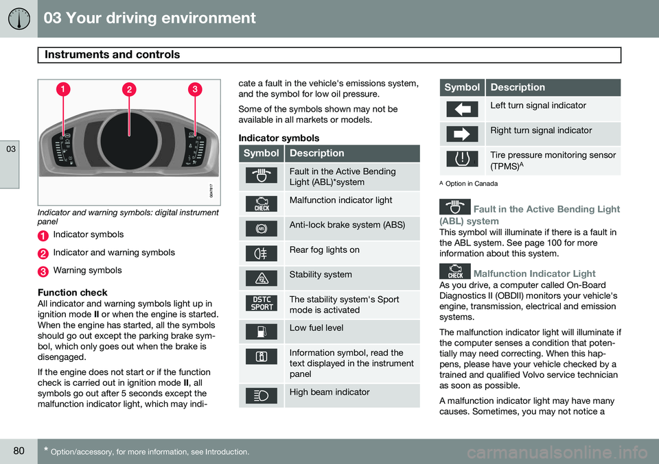
Indicator and warning symbols: digital instrument panel
Indicator symbols
Indicator and warning symbols
Warning symbols
Function checkAll indicator and warning symbols light up in ignition mode II or when the engine is started.
When the engine has started, all the symbolsshould go out except the parking brake sym-bol, which only goes out when the brake isdisengaged. If the engine does not start or if the function check is carried out in ignition mode II, all
symbols go out after 5 seconds except themalfunction indicator light, which may indi- cate a fault in the vehicle's emissions system,and the symbol for low oil pressure. Some of the symbols shown may not be available in all markets or models.
Indicator symbols
SymbolDescription
Fault in the Active Bending Light (ABL)*system
Malfunction indicator light
Anti-lock brake system (ABS)
Rear fog lights on
Stability system
The stability system's Sport mode is activated
Low fuel level
Information symbol, read the text displayed in the instrumentpanel
High beam indicator
SymbolDescription
Left turn signal indicator
Right turn signal indicator
Tire pressure monitoring sensor (TPMS)
A
A
Option in Canada
Fault in the Active Bending Light
(ABL) system
This symbol will illuminate if there is a fault in the ABL system. See page 100 for moreinformation about this system.
Malfunction Indicator Light
As you drive, a computer called On-Board Diagnostics II (OBDII) monitors your vehicle'sengine, transmission, electrical and emissionsystems. The malfunction indicator light will illuminate if the computer senses a condition that poten-tially may need correcting. When this hap-pens, please have your vehicle checked by atrained and qualified Volvo service technicianas soon as possible. A malfunction indicator light may have many causes. Sometimes, you may not notice a
Page 83 of 394
03 Your driving environment
Instruments and controls
03
* Option/accessory, for more information, see Introduction.81
change in your car's behavior. Even so, an uncorrected condition could hurt fuel econ-omy, emission controls, and drivability.Extended driving without correcting the causecould even damage other components inyour vehicle. This light may illuminate if the fuel filler cap is not closed tightly or if the engine was runningwhile the vehicle was refueled.
Anti-lock Brake System (ABS)
If the warning light comes on, there may be a malfunction in the ABS system (the standardbraking system will still function). Check thesystem by:
1. Stopping in a safe place and switching off
the ignition.
2. Restart the engine.
3. If the warning light goes off, no further action is required.
If the indicator light remains on, the vehicle should be driven to a trained and qualifiedVolvo service technician for inspection, seepage 131 for additional information.
Rear fog lights
This symbol indicates that the rear fog lights are on.
Stability system
This indicator symbol flashes when the DSTC (Dynamic Stability and Traction Control sys-tem) is actively working to stabilize the vehi-cle, see page 142 for more detailed informa-tion.
Sport mode
This symbol illuminates to indicate that the stability system's Sport mode has been acti-
vated to help provide maximum tractive force,for example when driving with snow chains,or driving in deep snow or loose sand.
Low fuel level
When this light comes on, the vehicle should be refueled as soon as possible. See page278 for information about fuel and refueling.
Information symbol
The information symbol lights up and a text message is displayed to provide the driverwith necessary information about one of thevehicle's systems. The message can beerased and the symbol can be turned off bypressing the OK button (see page 197 for
information) or this will take place automati-cally after a short time (the length of time var-ies, depending on the function affected). The information symbol may also illuminate together with other symbols.
High beam indicator
This symbol illuminates when the high beam headlights are on, or if the high beam flashfunction is used.
Left turn signal indicator
Right turn signal indicator
NOTE
• Both turn signal indicators will flash when the hazard warning flashers areused.
• If either of these indicators flash fasterthan normal, the direction indicatorsare not functioning properly.
Tire pressure monitoring system
(TPMS)*
This symbol illuminates to indicate that tire pressure in one or more tires is low, seepage 325 for detailed information.
Warning symbols
SymbolDescription
Low oil pressure
Parking brake applied
Page 84 of 394

03 Your driving environment
Instruments and controls
03
82
SymbolDescription
SRS airbags
Seat belt reminder
Generator not charging
Fault in the brake system
Warning symbol, read the text displayed in the instrumentpanel
Low oil pressure
If the light comes on while driving, stop the vehicle, stop the engine immediately, andcheck the engine oil level. Add oil if neces-sary. If the oil level is normal and the lightstays on after restart, have the vehicle towedto the nearest trained and qualified Volvoservice technician.
Parking brake applied
This symbol flashes while the brake is being applied and then glows steadily when theparking brake has been set. See page 134 for more information about using the parking brake.
Airbags – SRS
If this light comes on while the vehicle is being driven, or remains on for longer thanapproximately 10 seconds after the vehiclehas been started, the SRS system's diagnos-tic functions have detected a fault in a seatbelt lock or pretensioner, a front airbag, sideimpact airbag, and/or an inflatable curtain.Have the system(s) inspected by a trainedand qualified Volvo service technician assoon as possible. See page 21 for more information about the airbag system.
Seat belt reminder
This symbol comes on for approximately 6 seconds if the driver has not fastened his orher seat belt.
Generator not charging
This symbol comes on during driving if a fault has occurred in the electrical system. Contactan authorized Volvo workshop.
Engine temperatureEngine overheating can result from low oil or coolant levels, towing or hard driving at highheat and altitude, or mechanical malfunction.Engine overheating will be signaled with textand a red warning triangle in the middle of theinstrument display. The exact text will dependon the degree of overheating. It may rangefrom
High engine temp Reduce speed toHigh engine temp Stop engine. If appropri-
ate, other messages, such as Coolant level
low, Stop safely will also be displayed. If
your engine does overheat so that you must stop the engine, always allow the engine tocool before attempting to check oil and cool-ant levels. See page 338 for more information.
Fault in brake system
If this symbol lights, the brake fluid level may be too low. Stop the vehicle in a safe placeand check the level in the brake fluid reser-voir, see page 338. If the level in the reservoiris below MIN, the vehicle should be transpor-
ted to an authorized Volvo workshop to havethe brake system checked. If the
and symbols come on
at the same time, there may be a fault in the brake force distribution system.
1. Stop the vehicle in a safe place and turn off the engine.
2. Restart the engine.
• If both symbols extinguish, continue driv- ing.
• If the symbols remain on, check the levelin the brake fluid reservoir, see page 338.If the brake fluid level is normal but the
Page 85 of 394
03 Your driving environment
Instruments and controls
03
83
symbols are still lit, the vehicle can be driven, with great care, to an authorizedVolvo workshop to have the brake systemchecked.
• If the level in the reservoir is below
MIN,
the vehicle should be transported to anauthorized Volvo workshop to have thebrake system checked.
WARNING
• If the fluid level is below the
MIN mark
in the reservoir or if a warning mes- sage is displayed in the text window:DO NOT DRIVE . Have the vehicle
towed to a trained and qualified Volvoservice technician and have the brakesystem inspected.
• If the
and symbols
are on at the same time, there is a risk of reduced vehicle stability.
Warning symbol
The red warning symbol lights up to indicate a problem related to safety and/or drivability.A message will also appear in the instrumentpanel. The symbol remains visible until thefault has been rectified but the text messagecan be cleared with the OK button, see page 197. The warning symbol can alsocome on in conjunction with other symbols. Action:
1. Stop in a safe place. Do not drive the
vehicle further.
2. Read the information on the information display. Implement the action in accord- ance with the message in the display.Clear the message using OK.
Reminder – doors not closedIf one of the doors is not closed properly, the
information or warning symbol illuminates
(depending on the vehicle's speed), a graphic will be displayed in instrument panel and an explanatory text message 2
will also be dis-
played in the instrument panel. Stop the vehi- cle in a safe place as soon as possible andclose the door.
If the vehicle is driven at a speedlower than approximately 5 mph(7 km/h), the information symbol illu-
minates.
If the vehicle is driven at a speed higher than approximately 5 mph(7 km/h), the warning symbol illumi-
nates.
If the hood is not closed properly, the warn-
ing symbol illuminates, a graphic will be dis-
played in instrument panel and an explana- tory text message 2
will also be displayed in
the instrument panel. Stop the vehicle in a safe place as soon as possible and close thehood. If the tailgate is not closed properly, the
information symbol illuminates, a graphic will
be displayed in instrument panel and an explanatory text message 2
will also be dis-
played in the instrument panel. Stop the vehi- cle in a safe place as soon as possible andclose the tailgate.
2 Text message applies only to models with the optional digital instrument panel
Page 88 of 394
03 Your driving environment
Ignition modes
03
86* Option/accessory, for more information, see Introduction.
Inserting and removing the remote key
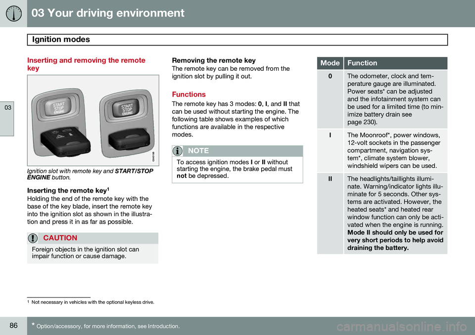
Ignition slot with remote key and START/STOP
ENGINE button.
Inserting the remote key 1Holding the end of the remote key with the base of the key blade, insert the remote keyinto the ignition slot as shown in the illustra-tion and press it in as far as possible.
CAUTION
Foreign objects in the ignition slot can impair function or cause damage.
Removing the remote keyThe remote key can be removed from the ignition slot by pulling it out.
Functions
The remote key has 3 modes:
0, I, and II that
can be used without starting the engine. The following table shows examples of whichfunctions are available in the respectivemodes.
NOTE
To access ignition modes I or II without
starting the engine, the brake pedal must not be depressed.
ModeFunction
0The odometer, clock and tem- perature gauge are illuminated.Power seats* can be adjustedand the infotainment system canbe used for a limited time (to min-imize battery drain seepage 230).
IThe Moonroof*, power windows, 12-volt sockets in the passengercompartment, navigation sys-tem*, climate system blower,windshield wipers can be used.
IIThe headlights/taillights illumi- nate. Warning/indicator lights illu-minate for 5 seconds. Other sys-tems are activated. However, theheated seats* and heated rearwindow function can only be acti-vated when the engine is running. Mode II should only be used for very short periods to help avoiddraining the battery.
1
Not necessary in vehicles with the optional keyless drive.