relay VOLVO XC70 2014 Owner´s Manual
[x] Cancel search | Manufacturer: VOLVO, Model Year: 2014, Model line: XC70, Model: VOLVO XC70 2014Pages: 394, PDF Size: 11.55 MB
Page 337 of 394

09 Maintenance and specifications
Hood and engine compartment09
335
Opening and closing the hood
G010951
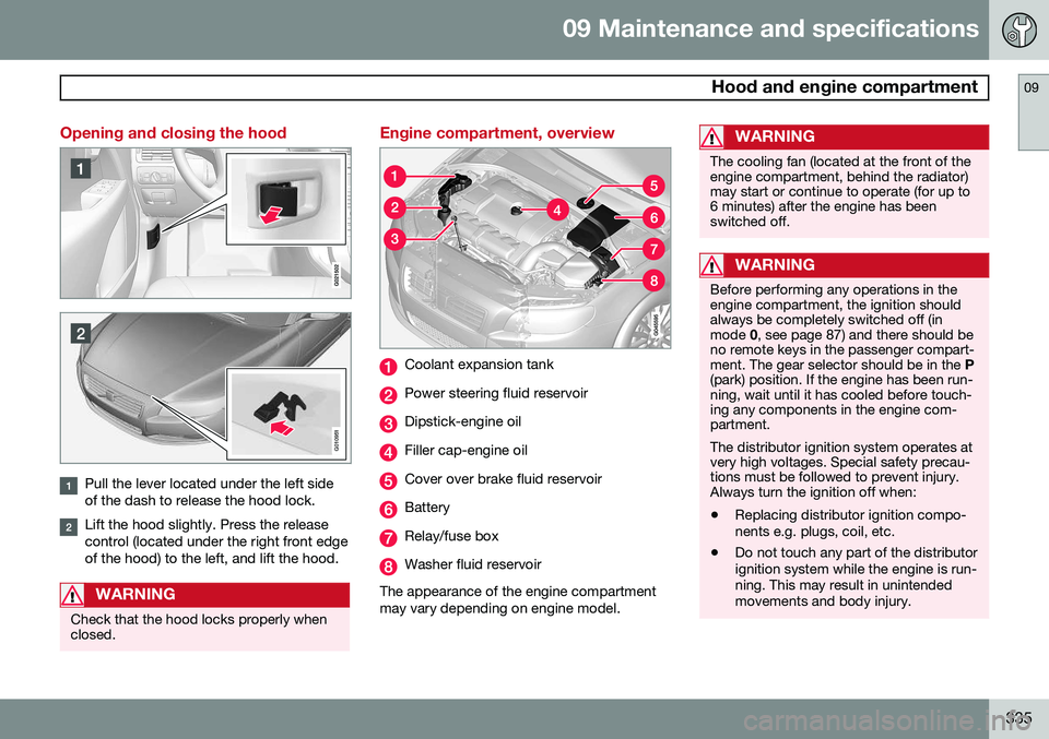
Pull the lever located under the left side of the dash to release the hood lock.
Lift the hood slightly. Press the release control (located under the right front edgeof the hood) to the left, and lift the hood.
WARNING
Check that the hood locks properly when closed.
Engine compartment, overview
Coolant expansion tank
Power steering fluid reservoir
Dipstick-engine oil
Filler cap-engine oil
Cover over brake fluid reservoir
Battery
Relay/fuse box
Washer fluid reservoir
The appearance of the engine compartment may vary depending on engine model.
WARNING
The cooling fan (located at the front of the engine compartment, behind the radiator)may start or continue to operate (for up to6 minutes) after the engine has beenswitched off.
WARNING
Before performing any operations in the engine compartment, the ignition shouldalways be completely switched off (inmode 0, see page 87) and there should be
no remote keys in the passenger compart-ment. The gear selector should be in the P
(park) position. If the engine has been run-ning, wait until it has cooled before touch-ing any components in the engine com-partment. The distributor ignition system operates at very high voltages. Special safety precau-tions must be followed to prevent injury.Always turn the ignition off when:
• Replacing distributor ignition compo- nents e.g. plugs, coil, etc.
• Do not touch any part of the distributorignition system while the engine is run-ning. This may result in unintendedmovements and body injury.
Page 356 of 394

09 Maintenance and specifications
Fuses 09
354
Replacing fuses
There are relay/fuse boxes located in the engine compartment, the passenger com-partment, and the cargo area. If an electrical component fails to function, this may be due to a blown fuse. The easiestway to see if a fuse is blown is to remove it. To do so:
1. Pull the fuse straight out. If a fuse is diffi-cult to remove, a special fuse removal tool is located on the inside of the enginecompartment fuse box cover.
2. From the side, examine the curved metal wire in the fuse to see if it is intact.
If the wire is broken, insert a new fuse of thesame color and amperage (written on thefuse). If fuses burn out repeatedly, have the electri- cal system inspected by a trained and quali-fied Volvo service technician.
WARNING
Never use metal objects or fuses with higher amperage than those stated on thefollowing pages. Doing so could seriouslydamage or overload the vehicle's electricalsystem.
Location of the fuse boxes
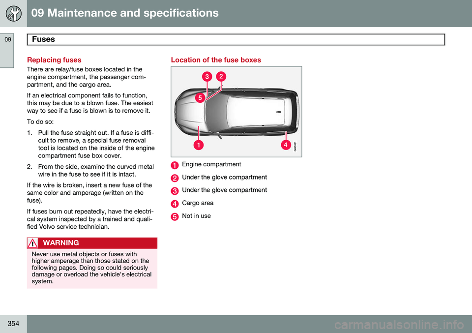
Engine compartment
Under the glove compartment
Under the glove compartment
Cargo area
Not in use
Page 358 of 394

09 Maintenance and specifications
Fuses 09
356* Option/accessory, for more information, see Introduction.
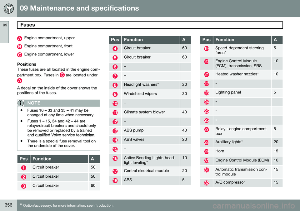
Engine compartment, upper
Engine compartment, front
Engine compartment, lower
PositionsThese fuses are all located in the engine com- partment box. Fuses in
are located under
.
A decal on the inside of the cover shows the positions of the fuses.
NOTE
• Fuses 16 – 33 and 35 – 41 may be changed at any time when necessary.
• Fuses 1 – 15, 34 and 42 – 44 arerelays/circuit breakers and should onlybe removed or replaced by a trainedand qualified Volvo service technician.
• There is a special fuse removal tool onthe underside of the cover.
PosFunctionA
Circuit breaker50
Circuit breaker50
Circuit breaker60
PosFunctionA
Circuit breaker60
Circuit breaker60
–
–
Headlight washers*20
Windshield wipers30
–
Climate system blower40
–
ABS pump40
ABS valves20
–
Active Bending Lights-head- light leveling*10
Central electrical module20
ABS5
PosFunctionA
Speed-dependent steering force*5
Engine Control Module (ECM), transmission, SRS10
Heated washer nozzles*10
-
Lighting panel5
-
-
-
Relay - engine compartment box5
Auxiliary lights*20
Horn15
Engine Control Module (ECM)10
Automatic transmission con- trol module15
A/C compressor15
Page 359 of 394

09 Maintenance and specifications
Fuses09
}}
357
PosFunctionA
Coils-A/C compressor5
Starter motor relay30
Ignition coils, condenser20
Engine Control Module10
Injection system, mass air meter, engine control module15
A/C compressor, engine valves, engine control mod-ule (6-cyl.), solenoids (6-cyl.non-turbo only)10
EVAP valve, heated oxygen sensor15
-
Fuel leakage detection5
–
Cooling fan80
Electro-hydraulic power steering100