engine VOLVO XC90 2006 Repair Manual
[x] Cancel search | Manufacturer: VOLVO, Model Year: 2006, Model line: XC90, Model: VOLVO XC90 2006Pages: 256, PDF Size: 6.87 MB
Page 189 of 256
2006 VOLVO XC90
pg. 153 Maintenance
Battery Maintenance
The battery in your vehicle is located under the floor of the cargo comp\
artment.
Driving habits and conditions, climate, the number of starts, etc. all a\
ffect the service life and function of
the battery. In order for your battery to perform satisfactorily, keep t\
he following in mind:
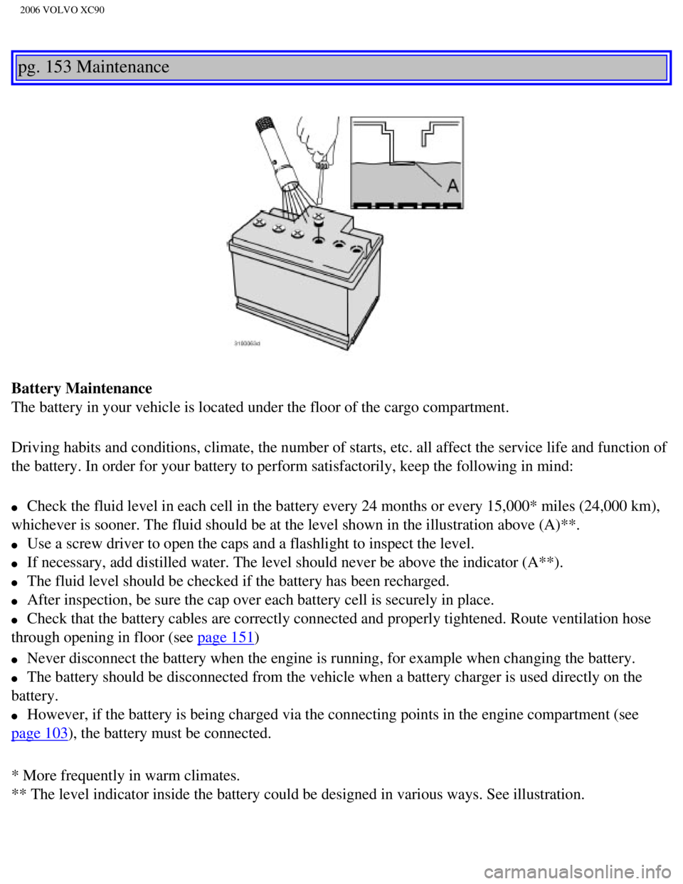
l Check the fluid level in each cell in the battery every 24 months or eve\
ry 15,000* miles (24,000 km),
whichever is sooner. The fluid should be at the level shown in the illus\
tration above (A)**.
l Use a screw driver to open the caps and a flashlight to inspect the leve\
l.
l If necessary, add distilled water. The level should never be above the i\
ndicator (A**).
l The fluid level should be checked if the battery has been recharged.
l After inspection, be sure the cap over each battery cell is securely in \
place.
l Check that the battery cables are correctly connected and properly tight\
ened. Route ventilation hose
through opening in floor (see
page 151)
l Never disconnect the battery when the engine is running, for example whe\
n changing the battery.
l The battery should be disconnected from the vehicle when a battery charg\
er is used directly on the
battery.
l However, if the battery is being charged via the connecting points in th\
e engine compartment (see
page 103), the battery must be connected.
* More frequently in warm climates.
** The level indicator inside the battery could be designed in various w\
ays. See illustration.
file:///K|/ownersdocs/2006/2006_XC90/06xc90_09b.htm (1 of 24)12/30/200\
6 5:32:52 PM
Page 205 of 256
2006 VOLVO XC90
Replacing fuses
If an electrical component fails to function, it is possible that a fuse\
has blown.
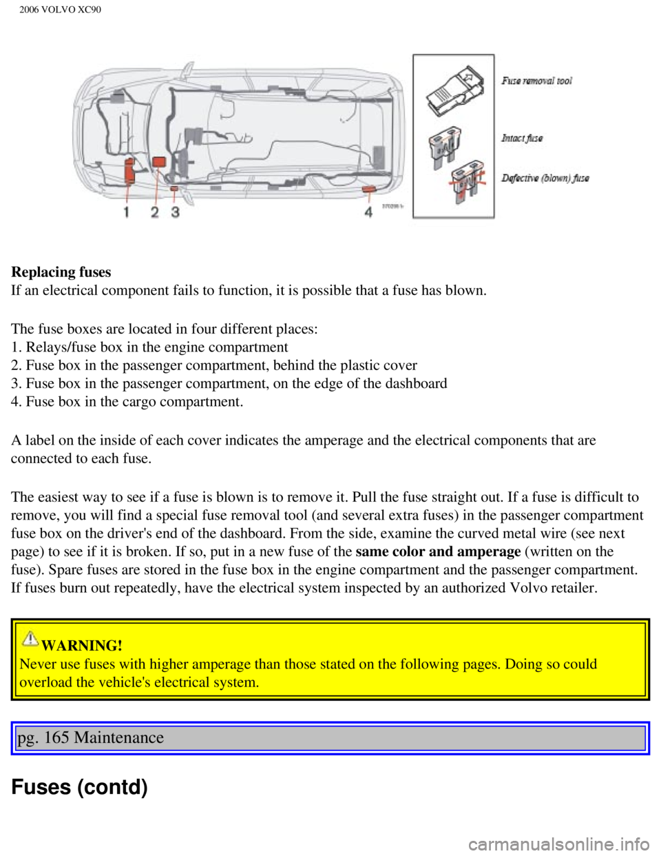
The fuse boxes are located in four different places:
1. Relays/fuse box in the engine compartment
2. Fuse box in the passenger compartment, behind the plastic cover
3. Fuse box in the passenger compartment, on the edge of the dashboard
4. Fuse box in the cargo compartment.
A label on the inside of each cover indicates the amperage and the elect\
rical components that are
connected to each fuse.
The easiest way to see if a fuse is blown is to remove it. Pull the fuse\
straight out. If a fuse is difficult to
remove, you will find a special fuse removal tool (and several extra fu\
ses) in the passenger compartment
fuse box on the driver's end of the dashboard. From the side, examine th\
e curved metal wire (see next
page) to see if it is broken. If so, put in a new fuse of the same color and amperage (written on the
fuse). Spare fuses are stored in the fuse box in the engine compartment\
and the passenger compartment.
If fuses burn out repeatedly, have the electrical system inspected by an\
authorized Volvo retailer.
WARNING!
Never use fuses with higher amperage than those stated on the following \
pages. Doing so could
overload the vehicle's electrical system.
pg. 165 Maintenance
Fuses (contd)
file:///K|/ownersdocs/2006/2006_XC90/06xc90_09b.htm (17 of 24)12/30/20\
06 5:32:52 PM
Page 206 of 256
2006 VOLVO XC90
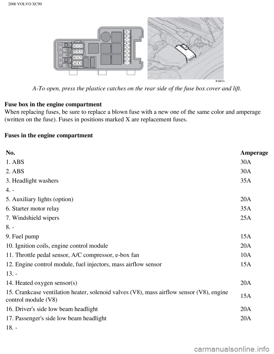
A-To open, press the plastice catches on the rear side of the fuse box c\
over and lift.
Fuse box in the engine compartment
When replacing fuses, be sure to replace a blown fuse with a new one of \
the same color and amperage
(written on the fuse). Fuses in positions marked X are replacement fus\
es.
Fuses in the engine compartment
No. Amperage
1. ABS 30A
2. ABS 30A
3. Headlight washers 35A
4. -
5. Auxiliary lights (option) 20A
6. Starter motor relay 35A
7. Windshield wipers 25A
8. -
9. Fuel pump 15A
10. Ignition coils, engine control module 20A
11. Throttle pedal sensor, A/C compressor, e-box fan 10A
12. Engine control module, fuel injectors, mass airflow sensor 15A
13. -
14. Heated oxygen sensor(s) 20A
15. Crankcase ventilation heater, solenoid valves (V8), mass airflow s\
ensor (V8), engine
control module (V8) 15A
16. Driver's side low beam headlight 20A
17. Passenger's side low beam headlight 20A
18. -
file:///K|/ownersdocs/2006/2006_XC90/06xc90_09b.htm (18 of 24)12/30/20\
06 5:32:52 PM
Page 207 of 256
2006 VOLVO XC90
19. Engine control module feed, engine relay 5A
20. Parking lights 15A
21. -
pg. 166 Maintenance
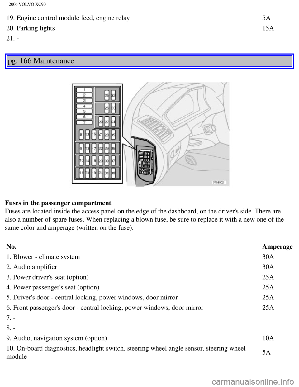
Fuses in the passenger compartment
Fuses are located inside the access panel on the edge of the dashboard, \
on the driver's side. There are
also a number of spare fuses. When replacing a blown fuse, be sure to re\
place it with a new one of the
same color and amperage (written on the fuse).
No. Amperage
1. Blower - climate system 30A
2. Audio amplifier 30A
3. Power driver's seat (option) 25A
4. Power passenger's seat (option) 25A
5. Driver's door - central locking, power windows, door mirror 25A
6. Front passenger's door - central locking, power windows, door mirror \
25A
7. -
8. -
9. Audio, navigation system (option) 10A
10. On-board diagnostics, headlight switch, steering wheel angle sensor,\
steering wheel
module 5A
file:///K|/ownersdocs/2006/2006_XC90/06xc90_09b.htm (19 of 24)12/30/20\
06 5:32:52 PM
Page 208 of 256

2006 VOLVO XC90
11. Ignition switch, SRS, engine control module, immobilizer, transmissi\
on control module
(V8) 7.5A
12. Ceiling lighting, upper electronic control module 10A
13. Moonroof (option) 15A
14. -
15. -
16. -
17. -
18. -
19. -
20. -
21. -
22. -
23. -
24. -
25. -
26. -
27. -
28. -
29. -
30. -
31. -
32. -
33. -
34. -
35. -
36. -
37. -
38.-
pg. 167 Maintenance
Fuses (contd)
file:///K|/ownersdocs/2006/2006_XC90/06xc90_09b.htm (20 of 24)12/30/20\
06 5:32:52 PM
Page 213 of 256
2006 VOLVO XC90
2 0 0 6
VOLVO XC90
Specifications
pg. 171 Specifications
Label information172
Weights173
Dimensions 174
Fluid capacities175
Engine oil176
Lubricants177
Electrical system179
Engine specifications180
All specifications are subject to change without prior notice.
pg. 172 Specifications
file:///K|/ownersdocs/2006/2006_XC90/06xc90_10.htm (1 of 10)12/30/2006\
5:32:53 PM
Page 215 of 256

2006 VOLVO XC90
Standards (FMVSS) specifications (USA) and Ministry of Transport (C\
MVSS) standards (Canada) Your
Volvo is designed to meet all applicable safety standards, as evidenced \
by the certification label on the
facing side of the driver's door. For further information regarding thes\
e regulations, please consult your
Volvo retailer.
6. Loads and Tire Pressures U.S. models only
Certain models will only have one decal, depending on the specifications\
of the vehicle.
7. Vehicle Identification Number (VIN)
1
The VIN plate is located on the top left surface of the dashboard. The V\
IN is also stamped on the right
hand door pillar.
8. Model plate
Vehicle Identification Number (VIN). Codes for color and upholstery, e\
tc. The plate is located in the
engine compartment, on the inside of the left front fender.
1. The Vehicle Identification Number (VIN) should always be quoted in \
all correspondence concerning
your vehicle with the retailer and when ordering parts.
pg. 173 Specifications
Weights
Gross vehicle weight* USACanada
5-seat, 5-cyl, FWD 5640
lbs -
5-seat, 5-cyl, AWD 5790
lbs 2630 kg
5-seat, 8-cyl, AWD 5900
lbs 2680 kg
7-seat, 5-cyl, FWD 5840
lbs -
7-seat, 5-cyl, AWD 6005
lbs 2720 kg
7-seat, 8-cyl, AWD 6080
lbs 2760 kg
Capacity weight
file:///K|/ownersdocs/2006/2006_XC90/06xc90_10.htm (3 of 10)12/30/2006\
5:32:53 PM
Page 218 of 256
2006 VOLVO XC90
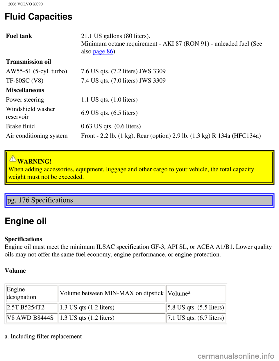
Fluid Capacities
Fuel tank 21.1 US gallons (80 liters).
Minimum octane requirement - AKI 87 (RON 91) - unleaded fuel (See
also
page 86)
Transmission oil
AW55-51 (5-cyl. turbo) 7.6 US qts. (7.2 liters) JWS 3309
TF-80SC (V8) 7.4 US qts. (7.0 liters) JWS 3309
Miscellaneous
Power steering 1.1 US qts. (1.0 liters)
Windshield washer
reservoir 6.9 US qts. (6.5 liters)
Brake fluid 0.63 US qts. (0.6 liters)
Air conditioning system Front - 2.2 lb. (1 kg), Rear (option) 2.9 lb. (1.3 kg) R 134a (HF\
C134a)
WARNING!
When adding accessories, equipment, luggage and other cargo to your vehi\
cle, the total capacity
weight must not be exceeded.
pg. 176 Specifications
Engine oil
Specifications
Engine oil must meet the minimum ILSAC specification GF-3, API SL, or AC\
EA A1/B1. Lower quality
oils may not offer the same fuel economy, engine performance, or engine \
protection.
Volume
Engine
designation Volume between MIN-MAX on dipstick
Volume
a
2.5T B5254T2 1.3 US qts (1.2 liters) 5.8 US qts. (5.5 liters)
V8 AWD B8444S 1.3 US qts (1.2 liters) 7.1 US qts. (6.7 liters)
a. Including filter replacement
file:///K|/ownersdocs/2006/2006_XC90/06xc90_10.htm (6 of 10)12/30/2006\
5:32:53 PM
Page 220 of 256
2006 VOLVO XC90
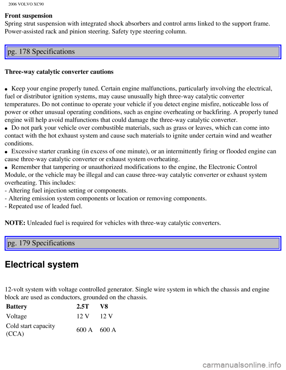
Front suspension
Spring strut suspension with integrated shock absorbers and control arms\
linked to the support frame.
Power-assisted rack and pinion steering. Safety type steering column.
pg. 178 Specifications
Three-way catalytic converter cautions
l Keep your engine properly tuned. Certain engine malfunctions, particular\
ly involving the electrical,
fuel or distributor ignition systems, may cause unusually high three-way\
catalytic converter
temperatures. Do not continue to operate your vehicle if you detect engi\
ne misfire, noticeable loss of
power or other unusual operating conditions, such as engine overheating \
or backfiring. A properly tuned
engine will help avoid malfunctions that could damage the three-way cata\
lytic converter.
l Do not park your vehicle over combustible materials, such as grass or le\
aves, which can come into
contact with the hot exhaust system and cause such materials to ignite u\
nder certain wind and weather
conditions.
l Excessive starter cranking (in excess of one minute), or an intermitte\
ntly firing or flooded engine can
cause three-way catalytic converter or exhaust system overheating.
l Remember that tampering or unauthorized modifications to the engine, the\
Electronic Control
Module, or the vehicle may be illegal and can cause three-way catalytic \
converter or exhaust system
overheating. This includes:
- Altering fuel injection setting or components.
- Altering emission system components or location or removing components\
.
- Repeated use of leaded fuel.
NOTE: Unleaded fuel is required for vehicles with three-way catalytic converte\
rs.
pg. 179 Specifications
Electrical system
12-volt system with voltage controlled generator. Single wire system in \
which the chassis and engine
block are used as conductors, grounded on the chassis.
Battery 2.5TV8
Voltage 12 V12 V
Cold start capacity
(CCA) 600 A
600 A
file:///K|/ownersdocs/2006/2006_XC90/06xc90_10.htm (8 of 10)12/30/2006\
5:32:53 PM
Page 221 of 256

2006 VOLVO XC90
Reserve capacity (RC) 120
min 120 min
If you must replace your battery, be sure to replace it with a battery o\
f the same cold start capacity and
reserve capacity as the original (See the decal on the battery). Generator max. current 140 A*170 A
Starter motor, power 1.4 kW 2.0 kW
Spark plugs P/N272313-8 or equivalent
Gap 0.028 in.0.7 mm
Tightening torque 22 ft. lbs. (30 Nm)
* Models equipped with the optional rear A/C unit have 160 A generators.\
pg. 180 Specifications
Engine specifications,
B5254T2 B8444S
Output (kW/rps) 154/83 232/100
- (hp/rpm) 208/5000 311/6000
Torque (Nm/rps) 320/1500-4500 440/3900
- (ft. lbs./rpm) 236/1500-4500 325/3900
No. of cylinders 5 8
Bore (in./mm) 3.27/83 3.7/94
Stroke (in./mm) 3.67/93.2 3.13/79.5
Cylinder displacement,
liters 2.52 (153.8 cu in)
4.41 (268.6 cu. in.)
Compression ratio 9.0:1 10.4:1
Charge air cooler (Intercooler)
Turbocharged engines employ a turbo-compressor to force air into the eng\
ine inlet manifold and a
charge air cooler to cool the compressed inlet air. The resulting increa\
se in air flow raises pressure in the
intake manifold and increases engine power over that developed by the no\
rmally-aspirated engine. The
charge air cooler (which resembles a radiator) is located between the \
turbo-compressor and inlet
manifold.
file:///K|/ownersdocs/2006/2006_XC90/06xc90_10.htm (9 of 10)12/30/2006\
5:32:53 PM