brake VOLVO XC90 2014 Owner´s Manual
[x] Cancel search | Manufacturer: VOLVO, Model Year: 2014, Model line: XC90, Model: VOLVO XC90 2014Pages: 308, PDF Size: 13.31 MB
Page 172 of 308
06 Starting and driving
Before a long distance trip
06
170
It is always worthwhile to have your vehicle checked by a trained and qualified Volvoservice technician before driving long dis-tances. Your retailer or service technician willalso be able to supply you with bulbs, fuses,spark plugs and wiper blades for your use inthe event that problems occur. As a minimum, the following items should be checked before any long trip:• Check that engine runs smoothly and that fuel consumption is normal.
• Check for fuel, oil, and fluid leakage.
• Check transmission oil level 1
.
• Check condition of drive belts.
• Check state of the battery's charge.
• Examine tires carefully (the spare tire aswell), and replace those that are worn.Check tire pressures.
• The brakes, front wheel alignment, andsteering gear should be checked by atrained and qualified Volvo service techni-cian only.
• Check all lights, including high beams.
• Reflective warning triangles are legallyrequired in some states/provinces. •
Have a word with your Volvo retailer ifyou intend to drive in countries where itmay be difficult to obtain the correct fuel.
• Consider your destination. If you will bedriving through an area where snow or iceare likely to occur, consider snow tires.
1
To prevent injury from contact with hot surfaces, do not inspect your vehicle’s transmission fluid yourself. Have your vehicle’s transmission fluid level inspected by a qualified Volvo service techni- cian.
Page 192 of 308
07 Wheels and tires
Snow chains, snow tires, studded tires
07
190
Snow chains
Snow chains can be used on your Volvo with the following restrictions:• Snow chains should be installed on front wheels only. Use only Volvo approvedsnow chains.
• If accessory, aftermarket or "custom"tires and wheels are installed and are of asize different than the original tires andwheels, chains in some cases CANNOTbe used. Sufficient clearances betweenchains and brakes, suspension and bodycomponents must be maintained.
• Some strap-on type chains will interferewith brake components and thereforeCANNOT be used.
• All Wheel Drive models: Snow chainsshould only be installed on the frontwheels.
• Certain size tires may not allow theassembly of snow chains/traction devi-ces.
Consult your Volvo retailer for additional snow chain information.CAUTION
• Check local regulations regarding the use of snow chains before installing.
• Always follow the chain manufactur-er's installation instructions carefully.Install chains as tightly as possible andretighten periodically.
• Never exceed the chain manufactur-er's specified maximum speed limit.(Under no circumstances should youexceed 31 mph (50 km/h)).
• Avoid bumps, holes or sharp turnswhen driving with snow chains.
• The handling of the vehicle can beadversely affected when driving withchains. Avoid fast or sharp turns aswell as locked wheel braking.
Snow tires, studded tires 1
Tires for winter use:
•
Owners who live in or regularly commute through areas with sustained periods ofsnow or icy driving conditions arestrongly advised to fit suitable winter tires to help retain the highest degree of trac-tion.
• It is important to install winter tires on allfour wheels to help retain traction duringcornering, braking, and accelerating. Fail-ure to do so could reduce traction to anunsafe level or adversely affect handling.
• Do not mix tires of different design as thiscould also negatively affect overall tireroad grip.
• Winter tires wear more quickly on dryroads in warm weather. They should beremoved when the winter driving seasonhas ended.
• Studded tires should be run-in300-600 miles (500-1000 km) duringwhich the vehicle should be driven assmoothly as possible to give the studsthe opportunity to seat properly in thetires. The tires should have the samerotational direction throughout their entirelifetime.NOTE
Please consult state or provincial regula- tions restricting the use of studded wintertires before installing such tires.
1
Where permitted
Page 196 of 308
07 Wheels and tires
Tire Sealing System
07
194
WARNING
•Never leave the tire sealing system unattended when it is operating.
• Keep the tire sealing system awayfrom children.
• Be sure the vehicle is parked safely offthe road and away from moving traffic.
• Apply the parking brake.
Stage 1: Sealing the hole1. Peel off the speed limit sticker and affix it
to the steering wheel hub where it will be clearly visible to the driver.
2. Ensure that the on/off switch is in position 0 (the 0 side of the switch should be
pressed down).
3. Put on the gloves included in the tire sealing system.
WARNING
Contact with the sealing compound may cause skin irritation. If contact occurs,wash the affected area immediately withsoap and water.
4. Unscrew the orange cover over the bottleholder and unscrew the cap on the bottle of sealing compound.
NOTE
Do not break the seal on the bottle. This occurs automatically when the bottle isscrewed into the holder.
5. Screw the bottle into the bottle holder.
WARNING
The bottle is equipped with a catch to keep it securely in place and help preventsealing compound leakage. Once in place,the bottle cannot be unscrewed. This mustbe done by a trained and qualified Volvoservice technician.
6. Remove the valve cap from the tire’sinflation valve and screw the tire sealing system’s hose connector onto the valveas tightly as possible by hand.
7. Connect the electrical wire to the nearest 12-volt socket in the vehicle.
NOTE
Be sure that none of the other 12-volt sockets is being used while the compres-sor is in operation.
8. Start the vehicle’s engine.
9. Start the tire sealing system’s compres- sor by pressing the on/off switch to posi- tion I.
WARNING
• Never stand next to the tire being infla- ted when the compressor is in opera-tion.
• If cracks, bubbles, etc. form on the tire,switch off the compressor immediately.
• If there is visible damage to the sidewallor the rim, the tire cannot be repaired.The vehicle should not be driven if thisoccurs. Contact a towing service orVolvo On Call Roadside Assistance ifapplicable.
Page 198 of 308
07 Wheels and tires
Tire Sealing System
07
196
system’s compressor. If necessary, release air from the tire by turning the airrelease knob counterclockwise.
CAUTION
The compressor should not be used for more than 10 minutes at a time to avoidoverheating.
WARNING
If you interrupt your trip for more than 1 hour, check the inflation pressure in thedamaged tire again before continuing.
Replacing the sealing compound container
The sealing compound container must be replaced if:• the tire sealing system has been used to repair a tire
• the container’s expiration date haspassed (see the date on decal).
NOTE
• After use, the sealing compound bot- tle, the hose, and certain other systemcomponents must be replaced. Pleaseconsult your Volvo retailer for replace-ment parts.
• If the sealing compound bottle’s expi-ration date has passed, please take itto a Volvo retailer or a recycling stationthat can properly dispose of harmfulsubstances.
Inflating tires
The tire sealing system can be used to inflate the tires. To do so:
1. Park the car in a safe place.
2. The compressor should be switched off.
Ensure that the on/off switch is in position 0 (the 0 side of the switch should be
pressed down).
3. Take out the electrical wire and hose.
4. Remove the valve cap from the tire’s inflation valve and screw the hose con- nector onto the valve as tightly as possi-ble by hand.
5. Connect the electrical wire to the nearest 12-volt socket in the vehicle. 6. Start the vehicle’s engine.
WARNING
•
The vehicle’s engine should be running when the tire sealing system is used toavoid battery drain. Therefore, be surethe vehicle is parked in a well ventilatedplace, or outdoors, before using thesystem. The parking brake should besecurely applied and the gear selectorshould be in the
P (park) position.
• Children should never be left unatten-ded in the vehicle when the engine isrunning.
7. Check the tire’s inflation pressure on the
gauge. Switch off the compressor briefly to get a clear reading from the pressuregauge.
8. Refer to the tire inflation tables for the correct inflation pressure. If the tire needsto be inflated, start the tire sealing sys-tem’s compressor (press the on/offswitch to position I). If necessary, releaseair from the tire by turning the air releaseknob counterclockwise.
Page 202 of 308
07 Wheels and tires
Changing wheels
07
200
G026997
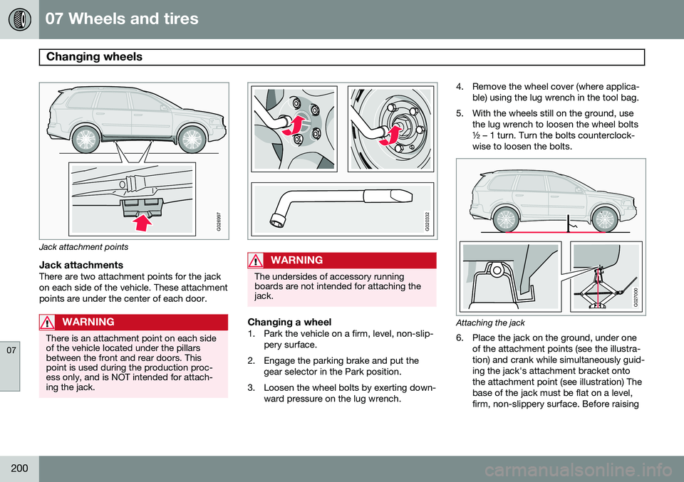
Jack attachment points
Jack attachmentsThere are two attachment points for the jack on each side of the vehicle. These attachmentpoints are under the center of each door.
WARNING
There is an attachment point on each side of the vehicle located under the pillarsbetween the front and rear doors. Thispoint is used during the production proc-ess only, and is NOT intended for attach-ing the jack.
G020332
WARNING
The undersides of accessory running boards are not intended for attaching thejack.
Changing a wheel1. Park the vehicle on a firm, level, non-slip-pery surface.
2. Engage the parking brake and put the gear selector in the Park position.
3. Loosen the wheel bolts by exerting down- ward pressure on the lug wrench. 4. Remove the wheel cover (where applica-
ble) using the lug wrench in the tool bag.
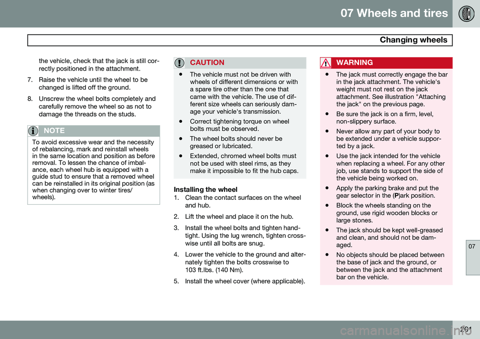
5. With the wheels still on the ground, use the lug wrench to loosen the wheel bolts ½ – 1 turn. Turn the bolts counterclock-wise to loosen the bolts.
G027000
Attaching the jack
6. Place the jack on the ground, under oneof the attachment points (see the illustra- tion) and crank while simultaneously guid-ing the jack's attachment bracket ontothe attachment point (see illustration) Thebase of the jack must be flat on a level,firm, non-slippery surface. Before raising
Page 203 of 308
07 Wheels and tires
Changing wheels
07
201
the vehicle, check that the jack is still cor- rectly positioned in the attachment.
7. Raise the vehicle until the wheel to be changed is lifted off the ground.
8. Unscrew the wheel bolts completely and carefully remove the wheel so as not todamage the threads on the studs.
NOTE
To avoid excessive wear and the necessity of rebalancing, mark and reinstall wheelsin the same location and position as beforeremoval. To lessen the chance of imbal-ance, each wheel hub is equipped with aguide stud to ensure that a removed wheelcan be reinstalled in its original position (aswhen changing over to winter tires/wheels).
CAUTION
•The vehicle must not be driven with wheels of different dimensions or witha spare tire other than the one thatcame with the vehicle. The use of dif-ferent size wheels can seriously dam-age your vehicle's transmission.
• Correct tightening torque on wheelbolts must be observed.
• The wheel bolts should never begreased or lubricated.
• Extended, chromed wheel bolts mustnot be used with steel rims, as theymake it impossible to fit the hub caps.
Installing the wheel1. Clean the contact surfaces on the wheel
and hub.
2. Lift the wheel and place it on the hub.
3. Install the wheel bolts and tighten hand- tight. Using the lug wrench, tighten cross- wise until all bolts are snug.
4. Lower the vehicle to the ground and alter- nately tighten the bolts crosswise to103 ft.lbs. (140 Nm).
5. Install the wheel cover (where applicable).
WARNING
• The jack must correctly engage the bar in the jack attachment. The vehicle'sweight must not rest on the jackattachment. See illustration "Attachingthe jack" on the previous page.
• Be sure the jack is on a firm, level,non-slippery surface.
• Never allow any part of your body tobe extended under a vehicle suppor-ted by a jack.
• Use the jack intended for the vehiclewhen replacing a wheel. For any otherjob, use stands to support the side ofthe vehicle being worked on.
• Apply the parking brake and put thegear selector in the (
P)ark position.
• Block the wheels standing on theground, use rigid wooden blocks orlarge stones.
• The jack should be kept well-greasedand clean, and should not be dam-aged.
• No objects should be placed betweenthe base of jack and the ground, orbetween the jack and the attachmentbar on the vehicle.
Page 211 of 308
08 Car care
Washing and cleaning the vehicle
08
209
Exterior componentsVolvo recommends the use of special clean- ing products, available at your Volvo retailer,for cleaning colored plastic, rubber, or orna-mental components such as chromed stripson the exterior of your vehicle. The instruc-tions for using these products should be fol-lowed carefully. Solvents or stain removersshould not be used.
CAUTION
•Avoid waxing or polishing plastic or rubber components
• Polishing chromed strips can wearaway or damage the surface
• Polishes containing abrasive sub-stances should not be used
NOTE
When washing the vehicle, remember to remove dirt from the drain holes in thedoors and sills.
WARNING
•When the vehicle is driven immediately after being washed, apply the brakesseveral times in order to remove anymoisture from the brake linings.
• Engine cleaning agents should not beused when the engine is warm. Thisconstitutes a fire risk.
Automatic washing – simple and quick
•
We do NOT recommend washing your vehicle in an automatic wash during thefirst few months (because the paint willnot have hardened sufficiently).
• An automatic wash is a simple and quickway to clean your vehicle, but it is worthremembering that it may not be as thor-ough as when you yourself go over thevehicle with sponge and water. Keepingthe underbody clean is most important,especially in the winter. Some automaticwashers do not have facilities for washingthe underbody.
• Before driving into an automatic carwash, make sure that side view mirrors,auxiliary lamps, etc, are secure, and thatany antenna(s) are retracted or removed.Otherwise there is risk of the machinedislodging them.
Exterior lightingCondensation may form temporarily on the inside of the lenses of exterior lights such asheadlights, fog lights, or tail lights. This is nor-mal and the lights are designed to withstandmoisture. Normally, condensation will dissi-pate after the lights have been on for a shorttime.
Polishing and waxing
•
Normally, polishing is not required during the first year after delivery, however, wax-ing may be beneficial.
• Before applying polish or wax the vehiclemust be washed and dried. Tar spots canbe removed with kerosene or tar remover.Difficult spots may require a fine rubbingcompound.
• After polishing use liquid or paste wax.
• Several commercially available productscontain both polish and wax.
• Waxing alone does not substitute for pol-ishing a dull surface.
• A wide range of polymer-based carwaxes can be purchased today. Thesewaxes are easy to use and produce along-lasting, high-gloss finish that pro-
Page 223 of 308
09 Maintenance and servicing
Engine compartment09
221
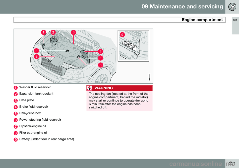
Washer fluid reservoir
Expansion tank-coolant
Data plate
Brake fluid reservoir
Relay/fuse box
Power steering fluid reservoir
Dipstick-engine oil
Filler cap-engine oil
Battery (under floor in rear cargo area)
WARNING
The cooling fan (located at the front of the engine compartment, behind the radiator)may start or continue to operate (for up to6 minutes) after the engine has beenswitched off.
Page 227 of 308
09 Maintenance and servicing
Fluids09
225
WARNING
•Never remove the coolant reservoir cap while the engine is warm. Waituntil the engine cools.
• If it is necessary to top up the coolantwhen the engine is warm, unscrew thecoolant reservoir cap slowly so thatthe overpressure dissipates.
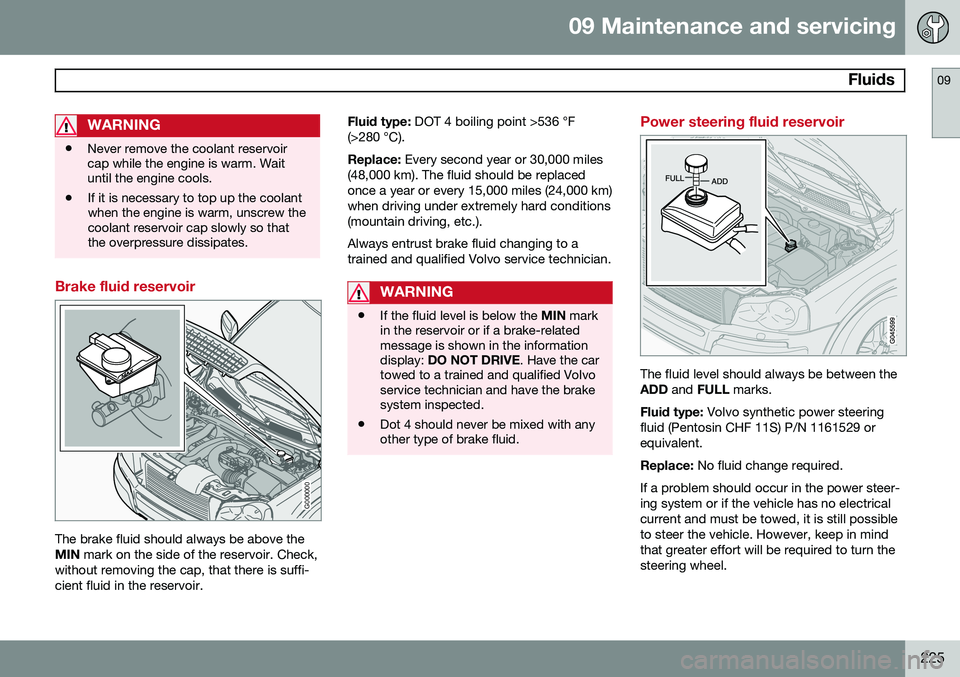
Brake fluid reservoir
G000000
The brake fluid should always be above the MIN
mark on the side of the reservoir. Check,
without removing the cap, that there is suffi-cient fluid in the reservoir. Fluid type:
DOT 4 boiling point >536 °F
(>280 °C). Replace: Every second year or 30,000 miles
(48,000 km). The fluid should be replaced once a year or every 15,000 miles (24,000 km)when driving under extremely hard conditions(mountain driving, etc.). Always entrust brake fluid changing to a trained and qualified Volvo service technician.
WARNING
• If the fluid level is below the
MIN mark
in the reservoir or if a brake-related message is shown in the informationdisplay: DO NOT DRIVE . Have the car
towed to a trained and qualified Volvoservice technician and have the brakesystem inspected.
• Dot 4 should never be mixed with anyother type of brake fluid.
Power steering fluid reservoir
The fluid level should always be between the ADD
and FULL marks.
Fluid type: Volvo synthetic power steering
fluid (Pentosin CHF 11S) P/N 1161529 orequivalent. Replace: No fluid change required.
If a problem should occur in the power steer- ing system or if the vehicle has no electricalcurrent and must be towed, it is still possibleto steer the vehicle. However, keep in mindthat greater effort will be required to turn thesteering wheel.
Page 232 of 308
09 Maintenance and servicing
Replacing bulbs 09
230* Option/accessory, for more information, see Introduction.
When replacing bulbs, keep the following points in mind:
• Never touch the glass of bulbs with your fingers. Grease and oils from your fingersvaporize in the heat and will leave adeposit on the reflector, which will dam-age it.
• The optional Active Bending Light bulbscontain trace amounts of mercury. Thesebulbs should always be disposed of by anauthorized Volvo retailer.
The following bulbs should only be replaced by a trained and qualified Volvo service tech-nician:
• Active Bending Lights (ABL)
• Daytime running lights (DRL) under the front bumper
• Turn signals and courtesy lights in theside door mirrors
• Reading lights and glove compartmentlight
• Courtesy (dome) lighting
• Rear parking lights
• Brake lights
• High-mounted brake lights
If a problem occurs with the daytime running lights (DRL) under the front bumper, the entirelamp housing will have to be replaced. If a problem occurs with the rear parkinglights or the brake lights, the entire taillighthousing will have to be replaced. See page 236 for a list of bulb specifications.
Replacing high/low beams/turn signal/parking light bulbs
WARNING
•
The engine should not be running when changing bulbs.
• If the engine has been running justprior to replacing bulbs in the head-light housing, please keep in mind thatcomponents in the engine compart-ment will be hot.
WARNING
Active Bending Lights* - due to the high voltage used by these headlights, thesebulbs should only be replaced by a trainedand qualified Volvo service technician.
G027081
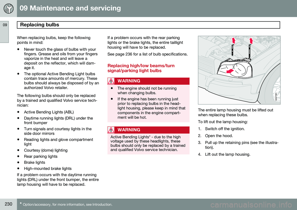
The entire lamp housing must be lifted out when replacing these bulbs. To lift out the lamp housing:
1. Switch off the ignition.
2. Open the hood.
3. Pull up the retaining pins (see the illustra-
tion).
4. Lift out the lamp housing.