park assist VOLVO XC90 2014 Owner´s Manual
[x] Cancel search | Manufacturer: VOLVO, Model Year: 2014, Model line: XC90, Model: VOLVO XC90 2014Pages: 308, PDF Size: 13.31 MB
Page 6 of 308
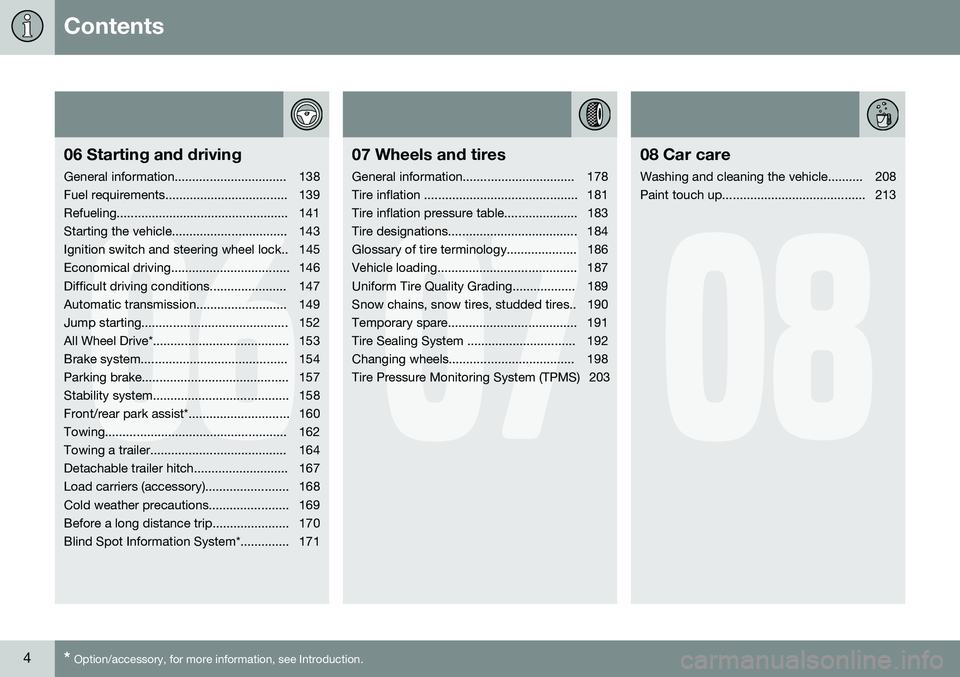
Contents
4* Option/accessory, for more information, see Introduction.
06
06 Starting and driving
General information................................ 138
Fuel requirements................................... 139
Refueling................................................. 141
Starting the vehicle................................. 143
Ignition switch and steering wheel lock.. 145
Economical driving.................................. 146
Difficult driving conditions...................... 147
Automatic transmission.......................... 149
Jump starting.......................................... 152
All Wheel Drive*....................................... 153
Brake system.......................................... 154
Parking brake.......................................... 157
Stability system....................................... 158
Front/rear park assist*............................. 160
Towing.................................................... 162
Towing a trailer....................................... 164
Detachable trailer hitch........................... 167
Load carriers (accessory)........................ 168
Cold weather precautions....................... 169
Before a long distance trip...................... 170
Blind Spot Information System*.............. 171
07
07 Wheels and tires
General information................................ 178
Tire inflation ............................................ 181
Tire inflation pressure table..................... 183
Tire designations..................................... 184
Glossary of tire terminology.................... 186
Vehicle loading........................................ 187
Uniform Tire Quality Grading.................. 189
Snow chains, snow tires, studded tires.. 190
Temporary spare..................................... 191
Tire Sealing System ............................... 192
Changing wheels.................................... 198
Tire Pressure Monitoring System (TPMS) 203
08
08 Car care
Washing and cleaning the vehicle.......... 208
Paint touch up......................................... 213
Page 16 of 308
Introduction
Important warnings
14
Driver distraction
A driver has a responsibility to do everything possible to ensure his or her own safety andthe safety of passengers in the vehicle andothers sharing the roadway. Avoiding distrac-tions is part of that responsibility. Driver distraction results from driver activities that are not directly related to controlling thevehicle in the driving environment. Your newVolvo is, or can be, equipped with many fea-ture-rich entertainment and communicationsystems. These include hands-free cellulartelephones, navigation systems, and multi-purpose audio systems. You may also ownother portable electronic devices for your ownconvenience. When used properly and safely,they enrich the driving experience. Improperlyused, any of these could cause a distraction. For all of these systems, we want to provide the following warning that reflects the strongVolvo concern for your safety. Never usethese devices or any feature of your vehicle ina way that distracts you from the task of driv-ing safely. Distraction can lead to a seriousaccident. In addition to this general warning,we offer the following guidance regardingspecific newer features that may be found inyour vehicle: •Never use a hand-held cellular telephone while driving. Some jurisdictions prohibit cellular telephone use by a driver whilethe vehicle is moving.
• If your vehicle is equipped with a naviga-tion system, set and make changes toyour travel itinerary only with the vehicleparked.
• Never program your audio system whilethe vehicle is moving. Program radio pre-sets with the vehicle parked, and useyour programmed presets to make radiouse quicker and simpler.
• Never use portable computers or per-sonal digital assistants while the vehicle ismoving.
Accessory installation
• We strongly recommend that Volvo own- ers install only genuine, Volvo-approvedaccessories, and that accessory installa-tions be performed only by a trained andqualified Volvo service technician.
• Genuine Volvo accessories are tested toensure compatibility with the perform-ance, safety, and emission systems inyour vehicle. Additionally, a trained andqualified Volvo service technician knowswhere accessories may and may not besafely installed in your Volvo. In all cases,please consult a trained and qualifiedVolvo service technician before installingany accessory in or on your vehicle. •
Accessories that have not been approvedby Volvo may or may not be specificallytested for compatibility with your vehicle.Additionally, an inexperienced installermay not be familiar with some of yourcar's systems.
• Any of your car's performance and safetysystems could be adversely affected ifyou install accessories that Volvo has nottested, or if you allow accessories to beinstalled by someone unfamiliar with yourvehicle.
• Damage caused by unapproved orimproperly installed accessories may notbe covered by your new vehicle warranty.See your Warranty and Service RecordsInformation booklet for more warrantyinformation. Volvo assumes no responsi-bility for death, injury, or expenses thatmay result from the installation of non-genuine accessories.
Page 67 of 308
02 Instruments and controls
Center console buttons
02
* Option/accessory, for more information, see Introduction.65
NOTE
If the door mirrors have been inadvertently pushed out of position (in a car wash,parking lot, etc.) manually return them tonormal position. If mirror adjustment doesnot seem to operate after manual folding,reset the folding mirrors as follows:
• Turn the ignition key to position
II.
• Manually fold the mirror(s) to the nor- mal position.
• Press the button to fold both mirrorsin.
• Press the button again to fold the mir-rors out to their normal position.
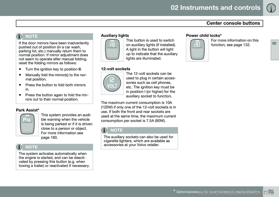
Park Assist*This system provides an audi- ble warning when the vehicleis being parked or if it is drivenclose to a person or object.For more information seepage 160.
NOTE
The system activates automatically when the engine is started, and can be deacti-vated by pressing this button (e.g. whentowing a trailer) or reactivated if necessary.
Auxiliary lightsThis button is used to switch on auxiliary lights (if installed).A light in the button will lightup to indicate that the auxiliarylights are illuminated.
12-volt socketsThe 12-volt sockets can be used to plug in certain acces-sories such as cell phones,etc. The ignition key must bein position I (or higher) for theauxiliary socket to function.
The maximum current consumption is 10A(120W) if only one of the 12-volt sockets is inuse. If both the front and rear sockets areused at the same time, the maximum currentconsumption per socket is 7.5A (90W).
NOTE
The auxiliary sockets can also be used for cigarette lighters, which are available asaccessories at your Volvo retailer.
Power child locks*For more information on this function, see page 132.
Page 138 of 308
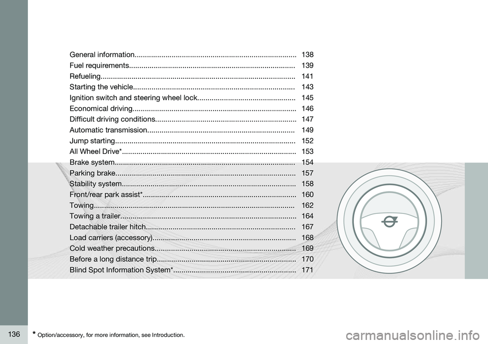
136* Option/accessory, for more information, see Introduction. General information............................................................................... 138
Fuel requirements................................................................................. 139Refueling............................................................................................... 141
Starting the vehicle............................................................................... 143
Ignition switch and steering wheel lock................................................ 145
Economical driving................................................................................ 146
Difficult driving conditions..................................................................... 147
Automatic transmission........................................................................ 149Jump starting........................................................................................ 152All Wheel Drive*..................................................................................... 153
Brake system........................................................................................154Parking brake........................................................................................ 157Stability system..................................................................................... 158
Front/rear park assist*........................................................................... 160Towing.................................................................................................. 162Towing a trailer...................................................................................... 164
Detachable trailer hitch......................................................................... 167
Load carriers (accessory)...................................................................... 168
Cold weather precautions..................................................................... 169
Before a long distance trip.................................................................... 170
Blind Spot Information System*............................................................ 171
Page 154 of 308
06 Starting and driving
Jump starting
06
152
G030860
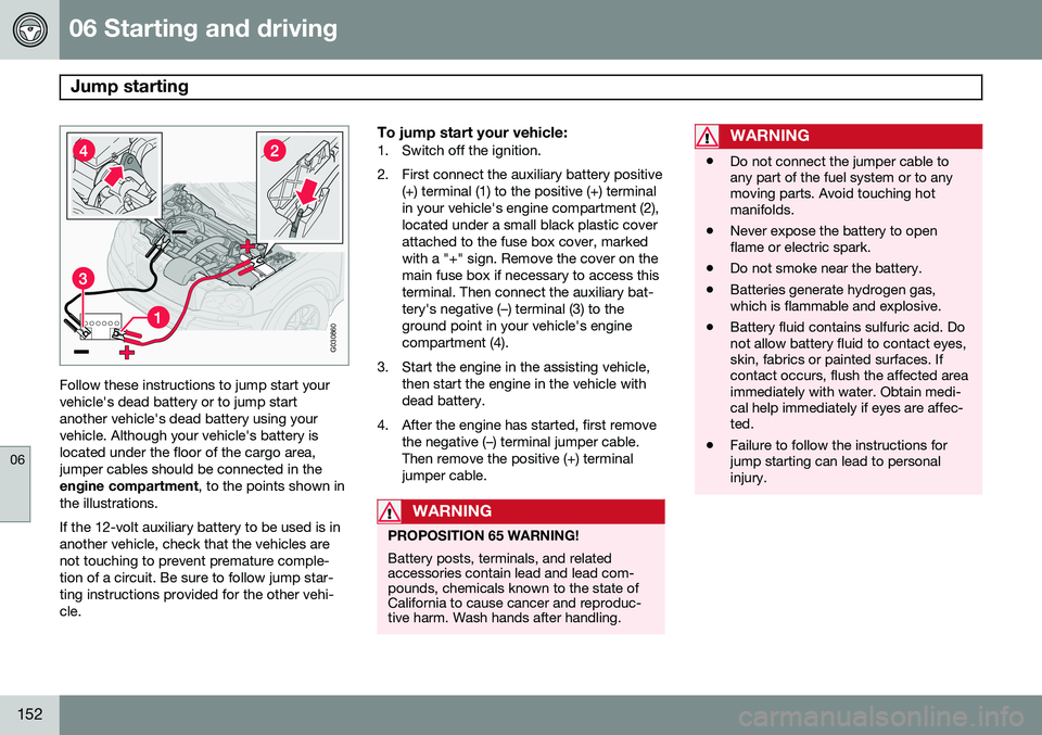
Follow these instructions to jump start your vehicle's dead battery or to jump startanother vehicle's dead battery using yourvehicle. Although your vehicle's battery islocated under the floor of the cargo area,jumper cables should be connected in theengine compartment, to the points shown in
the illustrations. If the 12-volt auxiliary battery to be used is in another vehicle, check that the vehicles arenot touching to prevent premature comple-tion of a circuit. Be sure to follow jump star-ting instructions provided for the other vehi-cle.
To jump start your vehicle:1. Switch off the ignition.
2. First connect the auxiliary battery positive (+) terminal (1) to the positive (+) terminal in your vehicle's engine compartment (2),located under a small black plastic coverattached to the fuse box cover, markedwith a "+" sign. Remove the cover on themain fuse box if necessary to access thisterminal. Then connect the auxiliary bat-tery's negative (–) terminal (3) to theground point in your vehicle's enginecompartment (4).
3. Start the engine in the assisting vehicle, then start the engine in the vehicle withdead battery.
4. After the engine has started, first remove the negative (–) terminal jumper cable.Then remove the positive (+) terminaljumper cable.
WARNING
PROPOSITION 65 WARNING! Battery posts, terminals, and related accessories contain lead and lead com-pounds, chemicals known to the state ofCalifornia to cause cancer and reproduc-tive harm. Wash hands after handling.
WARNING
•Do not connect the jumper cable to any part of the fuel system or to anymoving parts. Avoid touching hotmanifolds.
• Never expose the battery to openflame or electric spark.
• Do not smoke near the battery.
• Batteries generate hydrogen gas,which is flammable and explosive.
• Battery fluid contains sulfuric acid. Donot allow battery fluid to contact eyes,skin, fabrics or painted surfaces. Ifcontact occurs, flush the affected areaimmediately with water. Obtain medi-cal help immediately if eyes are affec-ted.
• Failure to follow the instructions forjump starting can lead to personalinjury.
Page 156 of 308
06 Starting and driving
Brake system
06
154* Option/accessory, for more information, see Introduction.
BRAKE Brake circuit malfunction
The brake system is a hydraulic system con- sisting of two master cylinders and two sepa-rate brake circuits. If a problem should occurin one of these circuits, it is still possible tostop the vehicle with the other brake circuit. If the brake pedal must be depressed farther than normal and requires greater foot pres-sure, the stopping distance will be longer. A warning light in the instrument panel will light up to warn the driver that a fault hasoccurred. If this light comes on while driving or braking, stop immediately and check the brake fluidlevel in the reservoir.
NOTE
Press the brake pedal hard and maintain pressure on the pedal – do not pump thebrakes.
WARNING
If the fluid level is below the MIN mark in
the reservoir or if a BRAKE FAILURE
STOP SAFELY message is displayed in
the text window: DO NOT DRIVE. Have
the vehicle towed to a trained and qualified Volvo service technician and have thebrake system inspected.
NOTE
When the vehicle is at a standstill and the engine is idling, e.g. at a traffic light andthe brake pedal is depressed, the pedalmay go down slightly. This is a normalfunction of the power-assisted brake sys-tem.
Brake pad inspectionOn vehicles equipped with a jack*, the condi- tion of the brake pads can be checked byraising the vehicle (see page 198 for informa-tion about using the jack and removing awheel) and performing a visual inspection ofthe brake pads.
WARNING
• If the vehicle has been driven immedi- ately prior to a brake pad inspection,the wheel hub, brake components,etc., will be very hot. Allow time forthese components to cool before car-rying out the inspection.
• Apply the parking brake and put thegear selector in the Park (
P) position.
• Block the wheels standing on theground, use rigid wooden blocks orlarge stones.
Page 158 of 308
06 Starting and driving
Brake system
06
156
ABS with EBD (Electronic Brake Force
Distribution)
EBD is an integrated part of the ABS system. EBD regulates the hydraulic pressure to therear brakes to help provide optimal brakingcapacity. The brake pedal will pulsate duringbraking, which is normal. If the BRAKE and ABS warning lights come on at the same time, this could indicate afault in the brake system.
1. Stop the vehicle in a suitable place and switch off the engine.
2. Restart the engine.
• If both warning lights go off, no further action is required.
• If both lights are still on after the enginehas been restarted, switch off the engineagain and check the brake fluid level (seepage 225 for the location of the brakefluid reservoir).
WARNING
If the fluid level is below the
MIN mark in
the reservoir or if a Brake failure –
Service urgent message is displayed in
the text window: DO NOT DRIVE. Have the vehicle towed to a trained and qualifiedVolvo service technician and have thebrake system inspected.
• If the brake fluid level is above the
MIN
mark, drive carefully to a trained and qualified Volvo service technician andhave the brake system inspected.
Emergency Brake Assistance (EBA)The EBA function is designed to provide full brake effect immediately in the event of sud-den, hard braking. The system is activated bythe speed with which you depress the brakepedal.
NOTE
• When the EBA system is activated, the brake pedal will go down and pressurein the brake system immediatelyincreases to the maximum level. Youmust maintain full pressure on thebrake pedal in order to utilize the sys-tem completely. There will be no brak-ing effect if the pedal is released. EBAis automatically deactivated when thebrake pedal is released.
• When the vehicle has been parked forsome time, the brake pedal may sinkmore than usual when the engine isstarted. This is normal and the pedalwill return to its usual position when itis released.
Page 162 of 308
06 Starting and driving
Front/rear park assist*
06
160* Option/accessory, for more information, see Introduction.
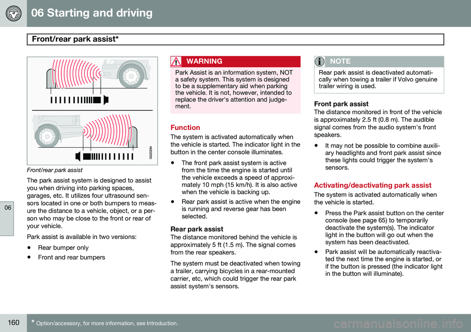
Front/rear park assist
The park assist system is designed to assist you when driving into parking spaces,garages, etc. It utilizes four ultrasound sen-sors located in one or both bumpers to meas-ure the distance to a vehicle, object, or a per-son who may be close to the front or rear ofyour vehicle. Park assist is available in two versions:
• Rear bumper only
• Front and rear bumpers
WARNING
Park Assist is an information system, NOT a safety system. This system is designedto be a supplementary aid when parkingthe vehicle. It is not, however, intended toreplace the driver's attention and judge-ment.
Function
The system is activated automatically when the vehicle is started. The indicator light in thebutton in the center console illuminates. • The front park assist system is active from the time the engine is started untilthe vehicle exceeds a speed of approxi-mately 10 mph (15 km/h). It is also activewhen the vehicle is backing up.
• Rear park assist is active when the engineis running and reverse gear has beenselected.
Rear park assistThe distance monitored behind the vehicle is approximately 5 ft (1.5 m). The signal comesfrom the rear speakers. The system must be deactivated when towing a trailer, carrying bicycles in a rear-mountedcarrier, etc, which could trigger the rear parkassist system's sensors.
NOTE
Rear park assist is deactivated automati- cally when towing a trailer if Volvo genuinetrailer wiring is used.
Front park assistThe distance monitored in front of the vehicle is approximately 2.5 ft (0.8 m). The audiblesignal comes from the audio system's frontspeakers.
• It may not be possible to combine auxili- ary headlights and front park assist sincethese lights could trigger the system'ssensors.
Activating/deactivating park assist
The system is activated automatically when the vehicle is started.
• Press the Park assist button on the center console (see page 65) to temporarilydeactivate the system(s). The indicatorlight in the button will go out when thesystem has been deactivated.
• Park assist will be automatically reactiva-ted the next time the engine is started, orif the button is pressed (the indicator lightin the button will illuminate).
Page 163 of 308
06 Starting and driving
Front/rear park assist*
06
* Option/accessory, for more information, see Introduction.161
NOTE
• Front park assist is disengaged auto- matically when the parking brake isapplied.
• If the vehicle is equipped with frontand rear park assist, both systems willbe deactivated by pressing the button.
Audible signals from the park assist system
The Park Assist system uses an intermittent tone that pulses faster as you come close toan object, and becomes constant when youare within approximately 1 ft (30 cm) of anobject in front of or behind the vehicle. If thevolume of another source from the audio sys-tem is high, this will be automatically lowered. If there are objects within this distance both behind and in front of the vehicle, the signalalternates between front and rear speakers.
Faults in the system
If the yellow warning symbol illu- minates and PARK ASSIST
SERVICE REQUIRED is shown
on the information display, this indicates that the system is not
functioning properly and has been disen-gaged. Consult a trained and qualified Volvoservice technician.
CAUTION
In certain circumstances, the park assist system may give unexpected warning sig-nals that can be caused by external soundsources that use the same ultrasound fre-quencies as the system. This may includesuch things as the horns of other vehicles,wet tires on asphalt, pneumatic brakes,motorcycle exhaust pipes, etc. This doesnot indicate a fault in the system.
Cleaning the sensors
G026946
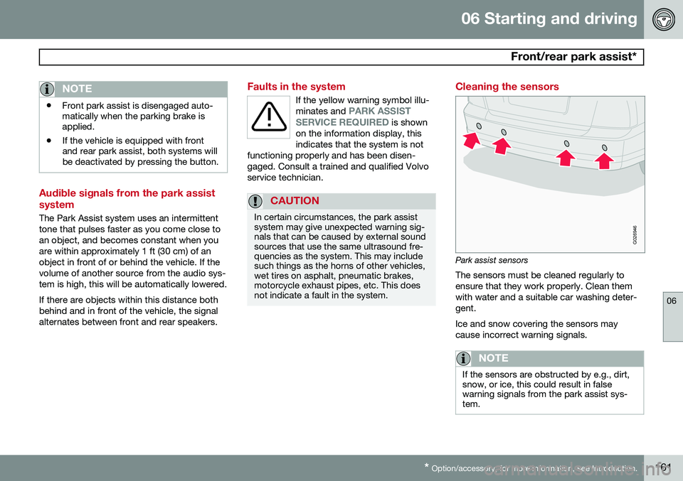
Park assist sensors The sensors must be cleaned regularly to ensure that they work properly. Clean themwith water and a suitable car washing deter-gent. Ice and snow covering the sensors may cause incorrect warning signals.
NOTE
If the sensors are obstructed by e.g., dirt, snow, or ice, this could result in falsewarning signals from the park assist sys-tem.
Page 196 of 308
07 Wheels and tires
Tire Sealing System
07
194
WARNING
•Never leave the tire sealing system unattended when it is operating.
• Keep the tire sealing system awayfrom children.
• Be sure the vehicle is parked safely offthe road and away from moving traffic.
• Apply the parking brake.
Stage 1: Sealing the hole1. Peel off the speed limit sticker and affix it
to the steering wheel hub where it will be clearly visible to the driver.
2. Ensure that the on/off switch is in position 0 (the 0 side of the switch should be
pressed down).
3. Put on the gloves included in the tire sealing system.
WARNING
Contact with the sealing compound may cause skin irritation. If contact occurs,wash the affected area immediately withsoap and water.
4. Unscrew the orange cover over the bottleholder and unscrew the cap on the bottle of sealing compound.
NOTE
Do not break the seal on the bottle. This occurs automatically when the bottle isscrewed into the holder.
5. Screw the bottle into the bottle holder.
WARNING
The bottle is equipped with a catch to keep it securely in place and help preventsealing compound leakage. Once in place,the bottle cannot be unscrewed. This mustbe done by a trained and qualified Volvoservice technician.
6. Remove the valve cap from the tire’sinflation valve and screw the tire sealing system’s hose connector onto the valveas tightly as possible by hand.
7. Connect the electrical wire to the nearest 12-volt socket in the vehicle.
NOTE
Be sure that none of the other 12-volt sockets is being used while the compres-sor is in operation.
8. Start the vehicle’s engine.
9. Start the tire sealing system’s compres- sor by pressing the on/off switch to posi- tion I.
WARNING
• Never stand next to the tire being infla- ted when the compressor is in opera-tion.
• If cracks, bubbles, etc. form on the tire,switch off the compressor immediately.
• If there is visible damage to the sidewallor the rim, the tire cannot be repaired.The vehicle should not be driven if thisoccurs. Contact a towing service orVolvo On Call Roadside Assistance ifapplicable.