SIM VOLVO XC90 2017 Owner´s Manual
[x] Cancel search | Manufacturer: VOLVO, Model Year: 2017, Model line: XC90, Model: VOLVO XC90 2017Pages: 560, PDF Size: 9.97 MB
Page 139 of 560
INSTRUMENTS AND CONTROLS
}}
* Option/accessory.137
Related information
•Calibrating the compass (p. 137)
• Ignition modes (p. 380)
Calibrating the compass
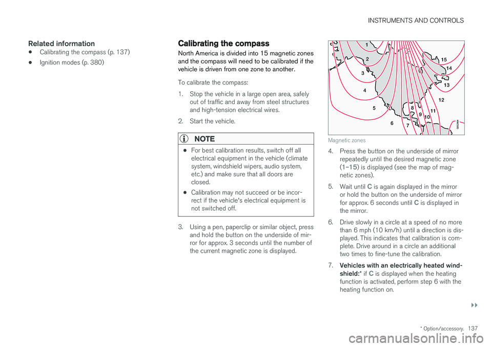
North America is divided into 15 magnetic zones and the compass will need to be calibrated if thevehicle is driven from one zone to another.
To calibrate the compass:
1. Stop the vehicle in a large open area, safely out of traffic and away from steel structures and high-tension electrical wires.
2. Start the vehicle.
NOTE
• For best calibration results, switch off all electrical equipment in the vehicle (climatesystem, windshield wipers, audio system,etc.) and make sure that all doors areclosed.
• Calibration may not succeed or be incor-rect if the vehicle's electrical equipment isnot switched off.
3. Using a pen, paperclip or similar object, press
and hold the button on the underside of mir- ror for approx. 3 seconds until the number ofthe current magnetic zone is displayed.
15
14
13
12
11
9
8
7
6
5
4
3
2
1
10
Magnetic zones
4. Press the button on the underside of mirrorrepeatedly until the desired magnetic zone (
1–15) is displayed (see the map of mag-
netic zones).
5. Wait until
C is again displayed in the mirror
or hold the button on the underside of mirror for approx. 6 seconds until
C is displayed in
the mirror.
6. Drive slowly in a circle at a speed of no more than 6 mph (10 km/h) until a direction is dis- played. This indicates that calibration is com-plete. Drive around in a circle an additionaltwo times to fine-tune the calibration.
7. Vehicles with an electrically heated wind- shield: * if
C is displayed when the heating
function is activated, perform step 6 with the heating function on.
Page 211 of 560
LOADING AND STORAGE
}}
* Option/accessory.209
Raising/lowering the rear-end of the vehicle*
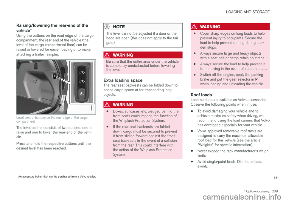
Using the buttons on the read edge of the cargo compartment, the rear-end of the vehicle (thelevel of the cargo compartment floor) can beraised or lowered for easier loading or to make attaching a trailer 1
simpler.
Level control buttons on the rear edge of the cargo compartment
The level control consists of two buttons: one to raise and one to lower the rear-end of the vehi-cle. Press and hold the respective buttons until the desired level has been reached.
NOTE
The level cannot be adjusted if a door or the hood are open (this does not apply to the tail-gate).
WARNING
Be sure that the entire area under the vehicle is completely unobstructed before loweringthe level.
Extra loading spaceThe rear seat backrests can be folded down to added cargo space or for transporting longobjects.
WARNING
• Boxes, suitcases, etc. wedged behind the front seats could impede the function ofthe Whiplash Protection System.
• If the rear seat backrests are foldeddown, cargo must be secured to preventit from sliding forward against the frontseat backrests in the event of a collisionfrom the rear. This could interfere withthe action of the Whiplash ProtectionSystem.
WARNING
• Cover sharp edges on long loads to help prevent injury to occupants. Secure theload to help prevent shifting during sud-den stops.
• Always secure large and heavy objectswith a seat belt or cargo retaining straps.
• Always secure the load to help prevent itfrom moving in the event of sudden stops.
• Switch off the engine, apply the parking brake and put the gear selector in
P
when loading and unloading the vehicle.
Roof loadsLoad carriers are available as Volvo accessories. Observe the following points when in use:
• To avoid damaging your vehicle and toachieve maximum safety when driving, werecommend using the load carriers that Volvohas developed especially for your vehicle.
• Volvo-approved removable roof racks aredesigned to carry the maximum allowableroof load for this vehicle (see the article"Weights" for specific information).
• Never exceed the rack manufacturer's weighlimits.
• Avoid single-point loads. Distribute loadsevenly.
1
An accessory trailer hitch can be purchased from a Volvo retailer.
Page 234 of 560
LOCKS AND ALARM
* Option/accessory.
232
Foot movement tailgate operation *
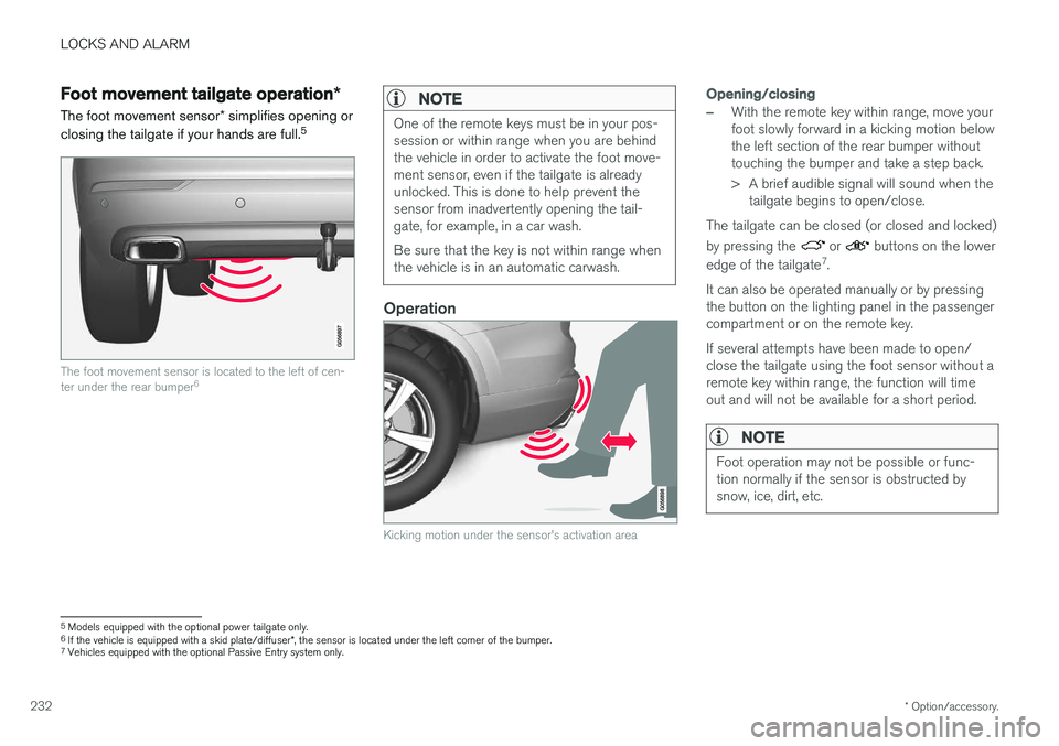
The foot movement sensor * simplifies opening or
closing the tailgate if your hands are full. 5
The foot movement sensor is located to the left of cen- ter under the rear bumper
6
NOTE
One of the remote keys must be in your pos- session or within range when you are behindthe vehicle in order to activate the foot move-ment sensor, even if the tailgate is alreadyunlocked. This is done to help prevent thesensor from inadvertently opening the tail-gate, for example, in a car wash. Be sure that the key is not within range when the vehicle is in an automatic carwash.
Operation
Kicking motion under the sensor's activation area
Opening/closing
–With the remote key within range, move your foot slowly forward in a kicking motion belowthe left section of the rear bumper withouttouching the bumper and take a step back.
> A brief audible signal will sound when the
tailgate begins to open/close.
The tailgate can be closed (or closed and locked) by pressing the
or buttons on the lower
edge of the tailgate 7
.
It can also be operated manually or by pressing the button on the lighting panel in the passengercompartment or on the remote key. If several attempts have been made to open/ close the tailgate using the foot sensor without aremote key within range, the function will timeout and will not be available for a short period.
NOTE
Foot operation may not be possible or func- tion normally if the sensor is obstructed bysnow, ice, dirt, etc.
5 Models equipped with the optional power tailgate only.
6 If the vehicle is equipped with a skid plate/diffuser *, the sensor is located under the left corner of the bumper.
7 Vehicles equipped with the optional Passive Entry system only.
Page 236 of 560
||
LOCKS AND ALARM
* Option/accessory.
234 system when a door is opened from inside the vehicle using a door handle. See also the article"Locking/unlocking from inside the vehicle" foradditional information. If the locks repeatedly do not react when the unlock button is pressed, begin by moving closerto the vehicle. However, it may be necessary toreplace the battery in the remote. In this case, thedriver's door can be unlocked with the detacha-ble key blade. See also the article "Detachablekey blade" for additional information.
Keyless Passive Entry
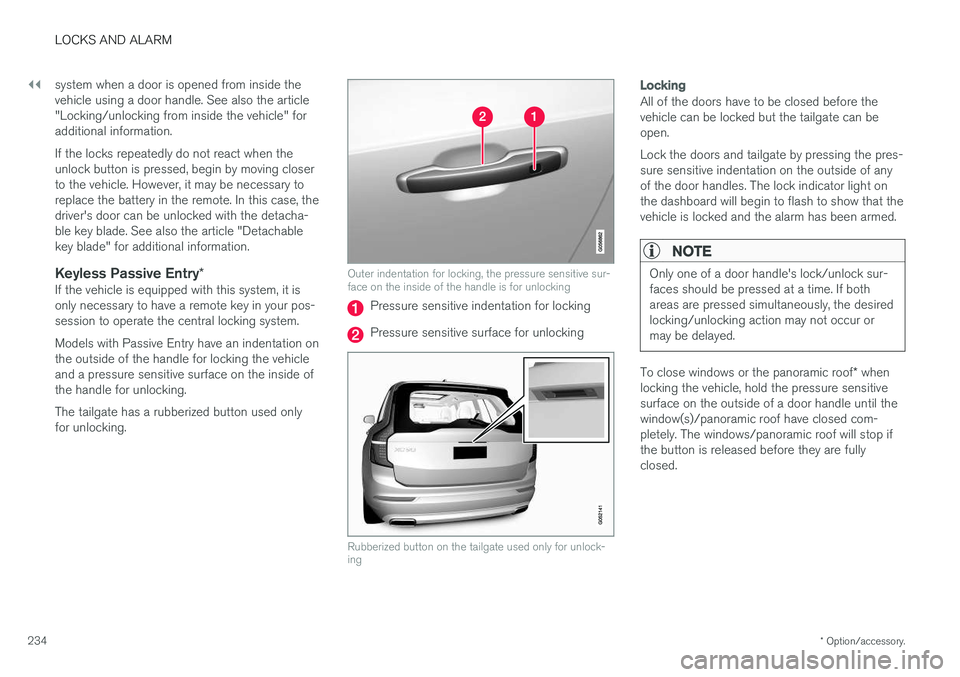
*If the vehicle is equipped with this system, it isonly necessary to have a remote key in your pos-session to operate the central locking system. Models with Passive Entry have an indentation on the outside of the handle for locking the vehicleand a pressure sensitive surface on the inside ofthe handle for unlocking. The tailgate has a rubberized button used only for unlocking.
Outer indentation for locking, the pressure sensitive sur- face on the inside of the handle is for unlocking
Pressure sensitive indentation for locking
Pressure sensitive surface for unlocking
Rubberized button on the tailgate used only for unlock- ing
Locking
All of the doors have to be closed before the vehicle can be locked but the tailgate can beopen. Lock the doors and tailgate by pressing the pres- sure sensitive indentation on the outside of anyof the door handles. The lock indicator light onthe dashboard will begin to flash to show that thevehicle is locked and the alarm has been armed.
NOTE
Only one of a door handle's lock/unlock sur- faces should be pressed at a time. If bothareas are pressed simultaneously, the desiredlocking/unlocking action may not occur ormay be delayed.
To close windows or the panoramic roof * when
locking the vehicle, hold the pressure sensitive surface on the outside of a door handle until thewindow(s)/panoramic roof have closed com-pletely. The windows/panoramic roof will stop ifthe button is released before they are fullyclosed.
Page 315 of 560
DRIVER SUPPORT
}}
313
Camera and radar sensor's field of vision
The camera and radar sensor have limited fields of vision. In some situations they may detect avehicle, large animal, pedestrian or cyclist laterthan expected or not detect them at all. Other vehicles that are dirty may be detected later than others and in dark conditions, motorcy-cles may be detected late or not at all. If a text message is displayed in the instrument panel indicates that the camera or radar sensorare blocked, it may be difficult for City Safety todetect a vehicle, pedestrian or cyclist and thesystem's functionality may be reduced.
WARNING
Text messages may not be displayed in all sit- uations in which the camera and/or radarsensor are blocked. It is therefore essential tokeep the windshield in front the camera/radarsensor clean and free from snow, ice, etc. Camera and radar sensor components should only be serviced or replaced by a trained andqualified Volvo service technician.
Action by the driver
Backing up
City Safety is temporarily deactivated while the vehicle is backing up.
Low speed
City Safety is not activated at very low speeds (under approx. 3 mph (4 km/h). This means thatthe system will not be triggered if your vehicleapproaches a vehicle ahead at very low speed,such as when parking.
Active driver
Action by the driver always has priority. For this reason, City Safety may not react or react laterthan expected in situations in which the driver isactively operating the vehicle, even if a collision isimminent. This is also done to help eliminateexcessive warnings.
Other limitations
City Safety uses the vehicle's camera and radar sensor, which have certain general limitations.See the articles "Camera limitations" and "Radarsensor limitations" for additional information.
WARNING
•
Warnings and braking may be delayed or not occur at all if traffic, weather or otherconditions prevent the camera and/orradar sensor from detecting pedestrians,cyclists, large animals or other vehiclescorrectly.
• Other vehicles can only be detected indarkness if their headlights and taillightsare clearly visible.
• The sensors have a limited range forpedestrians and cyclists. The systemfunctions best at relative speeds up to30 mph (50 km/h). For stationary orslow-moving vehicles, the system func-tions best at speeds up to approx.43 mph (70 km/h).
• If there is a risk of colliding with a largeanimal, City Safety can reduce the vehi-cle's speed by up to 9 mph (15 km/h).Warnings and braking are most effectiveat speeds above 43 mph (70 km/h) andless effective at lower speeds.
Page 336 of 560
||
DRIVER SUPPORT
* Option/accessory.
334 To activate Run-off Mitigation:
• Select (tap) the box for
Collision
Avoidance Assistance, Steering aid
during increased collision risk.
The setting selected when the engine was switched off will be used the next time theengine is started.
LimitationsIn certain situations, it may be difficult for Run-offMitigation to assist the driver. In such cases, it isadvisable to deactivate the function. Examples of these situations include:
• road construction
• winter driving conditions
• poor road surfaces
• narrow roads
• a very active driving style
• bad weather with reduced visibility
• edges or lines other than the lane's marker lines
• roads with indistinct or no lane marker lines
The Run-off Mitigation function use the vehicle'scamera, which has general limitations. See thearticle "Camera limitations".
WARNING
• Run-off Mitigation is only intended to assist the driver and does not function inall driving, weather, traffic or road condi-tions.
• This function cannot detect barriers, railsor similar obstructions at the side of aroad or traffic lane.
• As the driver, you have full responsibilityfor operating the vehicle in a safe man-ner.
Related information
•
Run-off Mitigation
* symbols and messages
(p. 335)
• Driving lane assistance (p. 328)
• Camera limitations (p. 301)
Page 340 of 560
DRIVER SUPPORT
* Option/accessory.
338
Park Assist limitations
The Park Assist system has certain limitations.
NOTE
A trailer hitch whose wiring is integrated with the vehicle's electrical system will be takeninto account when measuring the availablespace behind the vehicle.
NOTE
• The system will not detect high objects, such as a loading dock, etc.
• Certain materials or fabrics may not bedetected by the sensors. Objects made ofthese materials or people wearing cloth-ing made of these fabrics may not bedetected.
• Children or animals near the vehicle maynot always be detected.
• Objects such as chains, thin shiny polesor low objects may temporarily not bedetected by the system. This may resultin the pulsing tone unexpectedly stoppinginstead of changing to a constant tone asthe vehicle approaches the object. Insuch cases, use caution when backing upor stop the vehicle to help avoid damage.
• In certain circumstances, the park assistsystem may give unexpected warning sig-nals that can be caused by externalsound sources that use the same ultra-sound frequencies as the system. Thismay include such things as the horns ofother vehicles, wet tires on asphalt, pneu-matic brakes, motorcycle exhaust pipes,other vehicles with similar ultrasound sys-tems, etc. This does not indicate a fault inthe system.
Cleaning the sensors
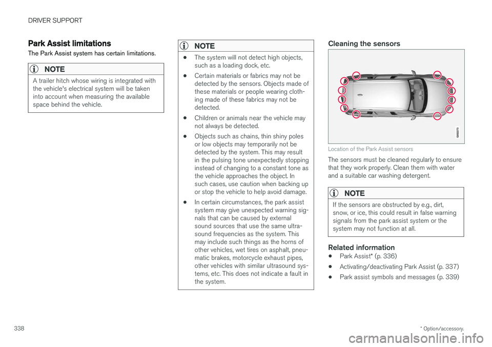
Location of the Park Assist sensors
The sensors must be cleaned regularly to ensure that they work properly. Clean them with waterand a suitable car washing detergent.
NOTE
If the sensors are obstructed by e.g., dirt, snow, or ice, this could result in false warningsignals from the park assist system or thesystem may not function at all.
Related information
•
Park Assist
* (p. 336)
• Activating/deactivating Park Assist (p. 337)
• Park assist symbols and messages (p. 339)
Page 344 of 560
DRIVER SUPPORT
* Option/accessory.
342 •
Park Assist
* (p. 336)
• Cross Traffic Alert (CTA)
* (p. 319)
• Park Assist Pilot (PAP)
* (p. 346)
Park Assist Camera (PAC) *
trajectory lines and fields
The Park Assist Camera system uses trajectory lines and fields to indicate the vehicle's positionin relation to its immediate surroundings.
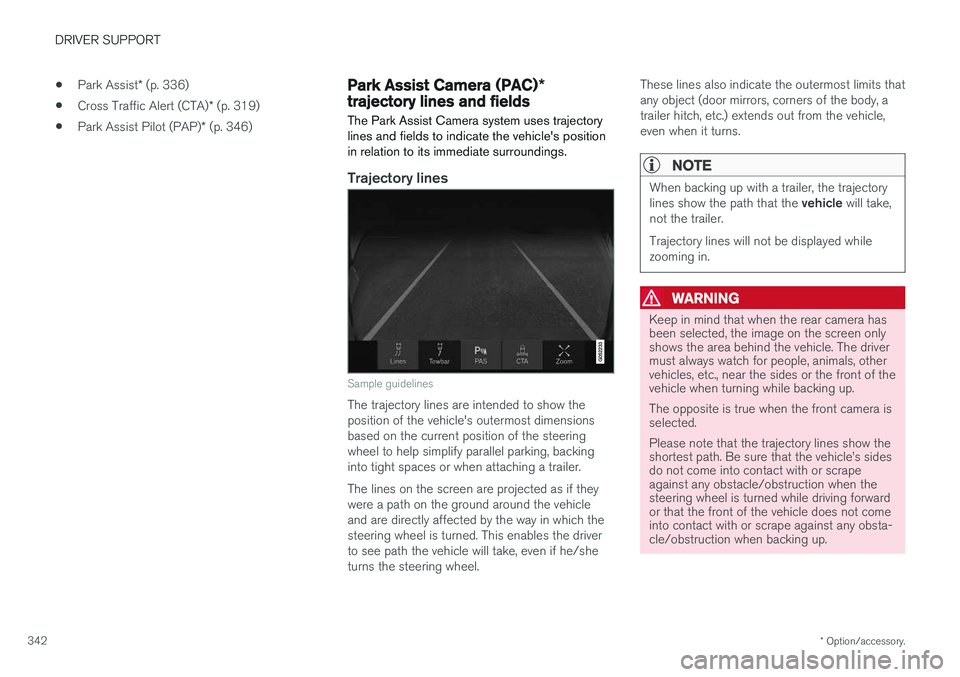
Trajectory lines
Sample guidelines
The trajectory lines are intended to show the position of the vehicle's outermost dimensionsbased on the current position of the steeringwheel to help simplify parallel parking, backinginto tight spaces or when attaching a trailer. The lines on the screen are projected as if they were a path on the ground around the vehicleand are directly affected by the way in which thesteering wheel is turned. This enables the driverto see path the vehicle will take, even if he/sheturns the steering wheel. These lines also indicate the outermost limits thatany object (door mirrors, corners of the body, atrailer hitch, etc.) extends out from the vehicle,even when it turns.
NOTE
When backing up with a trailer, the trajectory lines show the path that the
vehicle will take,
not the trailer. Trajectory lines will not be displayed while zooming in.
WARNING
Keep in mind that when the rear camera has been selected, the image on the screen onlyshows the area behind the vehicle. The drivermust always watch for people, animals, othervehicles, etc., near the sides or the front of thevehicle when turning while backing up. The opposite is true when the front camera is selected. Please note that the trajectory lines show the shortest path. Be sure that the vehicle
Page 371 of 560
STARTING AND DRIVING
}}
369
Towing recommendations
Always check with state and local authorities before attempting to tow another vehiclebecause this type of towing is subject to regula-tions regarding maximum towing speed, lengthand type of towing device, lighting, etc.
Towing your vehicle behind another vehicle
1. After securely attaching the towing line to both vehicles, put the gear selector in posi- tion N and release the parking brake.
2. Put the ignition in mode II by turning the
start knob to START (without depressing
the brake pedal) and hold it in this position
for approx. 4 seconds. Release the knob.
3. Put the gear selector in position N and
release the parking brake.
4. The towing vehicle can now begin driving.
5. Keep the tow rope taut when the towing vehicle slows down by applying light pressure on the brake pedal. This will help prevent jar-ring movements of the vehicle being towed.
6. Be prepared to apply the brakes to stop the vehicle being towed.
CAUTION
General towing precautions:
• If the vehicle's battery is dead, an auxiliary battery will be necessary to provide cur-rent for releasing the electric parkingbrake and to move the gear selector from the
P position to N. If this is not possible,
use the shiftlock override procedure tomanually release the gear selector from P
and move it to N.
• Maximum speed: 50 mph (80 km/h). Do not exceed the maximum allowable tow-ing speed.
• Maximum distance with front wheels onground: 50 miles (80 km).
• The vehicle should only be towed in theforward direction.
WARNING
• When the vehicle is being towed, the igni- tion should be in mode
II (in mode I, all of
the vehicle's airbags are deactivated).
• The remote key must remain inside the vehicle.
• The power brakes and power steering willnot function when the engine is not run-ning. Approximately 5 times more pres-sure will be required on the brake pedaland the steering wheel will be considera-bly harder to turn.
• The towing eyelets must not be used forpulling the vehicle out of a ditch or forany similar purpose involving severestrain.
Page 396 of 560
||
STARTING AND DRIVING
* Option/accessory.
394 from the
P or D positions into N so that the vehi-
cle can be moved. To do so:
Lift away the rubber mat on the bottom of the storage compartment in front of the gearselector to expose the small hole for overrid-ing the shiftlock feature.
Press a small screwdriver or similar item into the hole and hold it down.
Press the button on the front side of the gear selector and move the selector to the N
position. Release the button and remove the screwdriver from the hole.
4. Put the rubber mat back into place.
Related information
• Gear selector positions (p. 394)
• Automatic transmission (p. 392)
Gear shift indicator
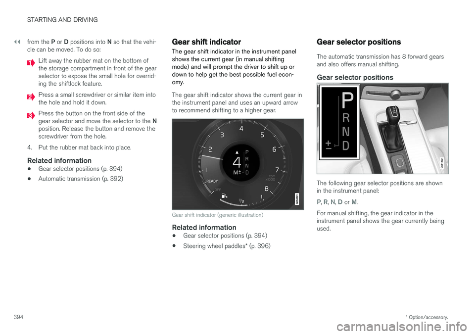
The gear shift indicator in the instrument panel shows the current gear (in manual shiftingmode) and will prompt the driver to shift up ordown to help get the best possible fuel econ-omy.
The gear shift indicator shows the current gear in the instrument panel and uses an upward arrowto recommend shifting to a higher gear.
Gear shift indicator (generic illustration)
Related information
• Gear selector positions (p. 394)
• Steering wheel paddles
* (p. 396)
Gear selector positions
The automatic transmission has 8 forward gears and also offers manual shifting.
Gear selector positions
The following gear selector positions are shown in the instrument panel:
P, R, N, D or M.
For manual shifting, the gear indicator in the instrument panel shows the gear currently beingused.