service indicator VOLVO XC90 T8 2017 Owner´s Manual
[x] Cancel search | Manufacturer: VOLVO, Model Year: 2017, Model line: XC90 T8, Model: VOLVO XC90 T8 2017Pages: 580, PDF Size: 10.37 MB
Page 381 of 580
STARTING AND DRIVING
}}
379
inspection programs will make detection of mis- fueling easier, possibly resulting in emission testfailure for misfueled vehicles.
NOTE
Some U.S. and Canadian gasolines contain an octane enhancing additive called methyl-cyclopentadienyl manganese tricarbonyl(MMT). If such fuels are used, your EmissionControl System performance may be affected,and the Check Engine Light (malfunctionindicator light) located on your instrumentpanel may light. If this occurs, please returnyour vehicle to a trained and qualified Volvoservice technician for service.
Gasoline containing alcohol and ethers, "Oxygenated fuels"
Some fuel suppliers sell gasoline containing "oxygenates" which are usually alcohols orethers. In some areas, state or local laws requirethat the service pump be marked indicating useof alcohols or ethers. However, there are areas inwhich the pumps are unmarked. If you are notsure whether there is alcohol or ethers in thegasoline you buy, check with the service stationoperator. To meet seasonal air quality standards,some areas require the use of "oxygenated" fuel. Volvo allows the use of the following "oxygen- ated" fuels; however, the octane ratings listedmust still be met.
Alcohol – Ethanol
Fuels containing up to 10% ethanol by volume may be used. Ethanol may also be referred to asEthyl alcohol, or "Gasohol". Ethers – MTBE: Fuels containing up to 15% MTBE may be used.
MethanolDo not use gasolines containing methanol(methyl alcohol, wood alcohol). This practice canresult in vehicle performance deterioration andcan damage critical parts in the fuel system. Suchdamage may not be covered under the NewVehicle Limited Warranty.
Related information
•
Octane rating (p. 379)
• Opening/closing the fuel filler door (p. 380)
Octane rating Volvo requires premium fuel (91 octane or above) for best performance.
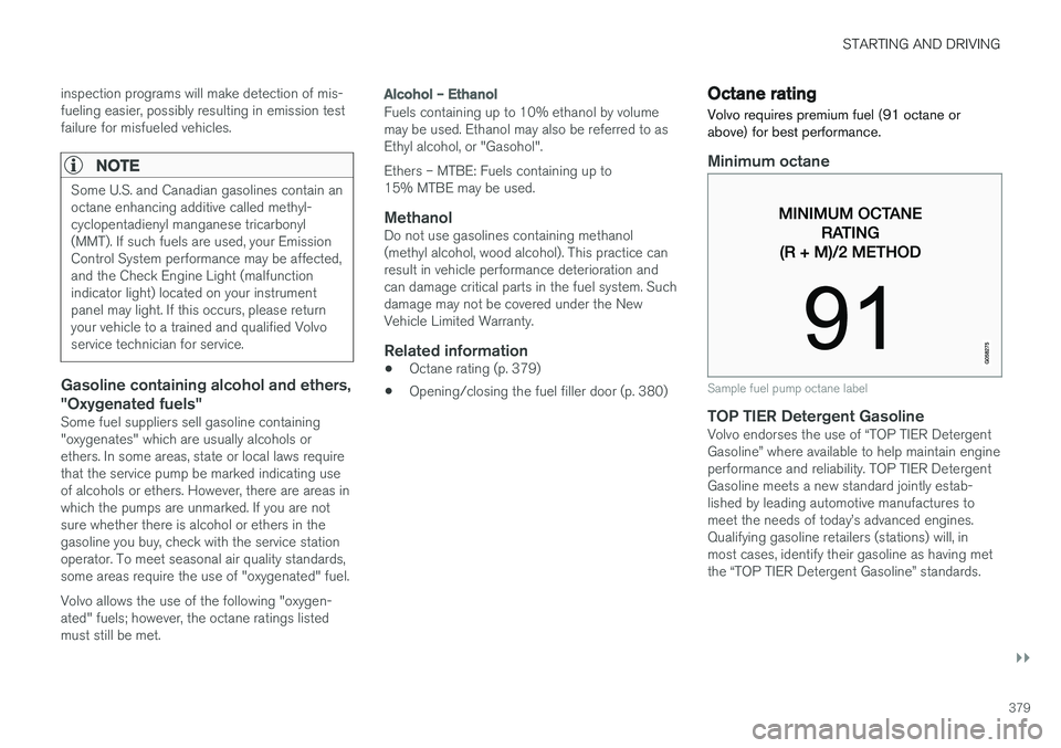
Minimum octane
Sample fuel pump octane label
TOP TIER Detergent GasolineVolvo endorses the use of “TOP TIER Detergent Gasoline” where available to help maintain engineperformance and reliability. TOP TIER DetergentGasoline meets a new standard jointly estab-lished by leading automotive manufactures tomeet the needs of today
Page 383 of 580
STARTING AND DRIVING
}}
381
2. After refueling, close the fuel filler door by
pressing lightly.
Refueling from a service station pump
To refuel:
1. Open the fuel filler door. Do not refuel with
the engine running 1
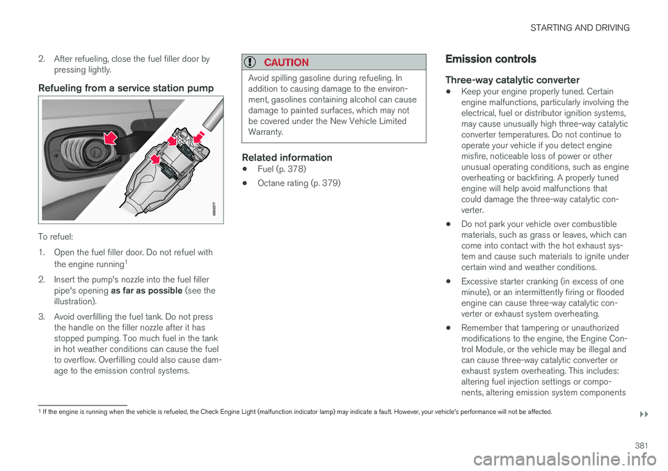
2. Insert the pump's nozzle into the fuel filler pipe's opening as far as possible (see the
illustration).
3. Avoid overfilling the fuel tank. Do not press the handle on the filler nozzle after it has stopped pumping. Too much fuel in the tankin hot weather conditions can cause the fuelto overflow. Overfilling could also cause dam-age to the emission control systems.
CAUTION
Avoid spilling gasoline during refueling. In addition to causing damage to the environ-ment, gasolines containing alcohol can causedamage to painted surfaces, which may notbe covered under the New Vehicle LimitedWarranty.
Related information
• Fuel (p. 378)
• Octane rating (p. 379)
Emission controls
Three-way catalytic converter
•Keep your engine properly tuned. Certain engine malfunctions, particularly involving theelectrical, fuel or distributor ignition systems,may cause unusually high three-way catalyticconverter temperatures. Do not continue tooperate your vehicle if you detect enginemisfire, noticeable loss of power or otherunusual operating conditions, such as engineoverheating or backfiring. A properly tunedengine will help avoid malfunctions thatcould damage the three-way catalytic con-verter.
• Do not park your vehicle over combustiblematerials, such as grass or leaves, which cancome into contact with the hot exhaust sys-tem and cause such materials to ignite undercertain wind and weather conditions.
• Excessive starter cranking (in excess of oneminute), or an intermittently firing or floodedengine can cause three-way catalytic con-verter or exhaust system overheating.
• Remember that tampering or unauthorizedmodifications to the engine, the Engine Con-trol Module, or the vehicle may be illegal andcan cause three-way catalytic converter orexhaust system overheating. This includes:altering fuel injection settings or compo-nents, altering emission system components
1
If the engine is running when the vehicle is refueled, the Check Engine Light (malfunction indicator lamp) may indicate a fault. However, your vehicle's performance will not be affected.
Page 398 of 580
||
STARTING AND DRIVING
396
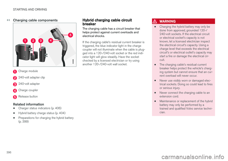
Charging cable components
Charge module
240-volt adapter clip
240-volt adapter
Charge coupler
Release button
Related information
•Charger status indicators (p. 406)
• Hybrid battery charge status (p. 404)
• Preparations for charging the hybrid battery (p. 399)
Hybrid charging cable circuit breaker
The charging cable has a circuit breaker that helps protect against current overloads andelectrical shocks.
If the charging cable's residual current breaker is triggered, the blue indicator light in the chargecoupler will not illuminate when the cable is plug-ged into a 120-/240-volt socket or the red indi-cator light will glow steadily. Have the socketchecked by a licensed electrician or try usinganother 120-/240-volt wall socket.
WARNING
• Charging the hybrid battery may only be done from approved, grounded 120-/240-volt sockets. If the electrical circuitor electrical socket's capacity is notknown, let a licensed electrician inspectthe electrical circuit's capacity. Using acharge level that exceeds the electricalcircuit's or electrical outlet's capacity maystart a fire or damage the electrical cir-cuit.
• The charging cable's residual currentbreaker helps protect the vehicle's charg-ing system but cannot ensure that an cur-rent overload will never occur.
• Never use visibly worn or damaged elec-trical sockets. Doing so could lead to firesor serious injury.
• Never connect the charging cable to anextension cord.
• Maintenance or replacement of the hybridbattery may only be performed by atrained and qualified Volvo service techni-cian.
Page 399 of 580
STARTING AND DRIVING
}}
397
Hybrid-related symbols and messages
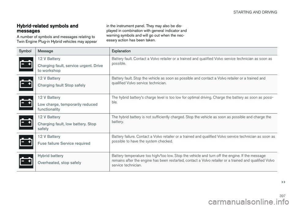
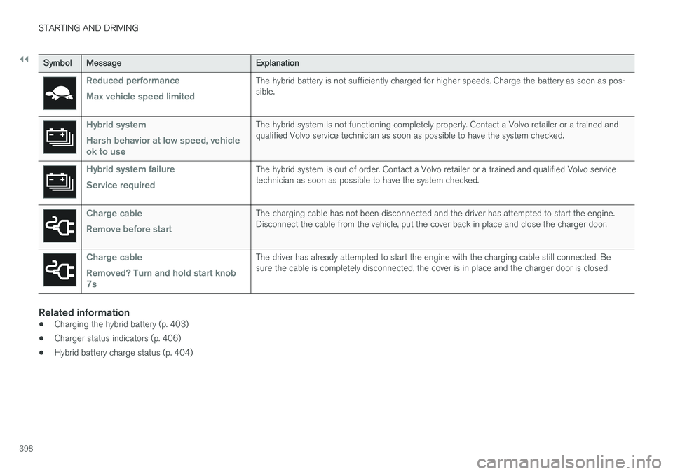
A number of symbols and messages relating to Twin Engine Plug-in Hybrid vehicles may appear in the instrument panel. They may also be dis-played in combination with general indicator andwarning symbols and will go out when the nec-essary action has been taken.
Symbol
Message Explanation
12 V Battery Charging fault, service urgent. Drive to workshopBattery fault. Contact a Volvo retailer or a trained and qualified Volvo service technician as soon as possible.
12 V Battery Charging fault Stop safelyBattery fault. Stop the vehicle as soon as possible and contact a Volvo retailer or a trained and qualified Volvo service technician.
12 V Battery Low charge, temporarily reduced functionalityThe hybrid battery's charge level is too low for optimal driving. Charge the battery as soon as possi- ble.
12 V Battery Charging fault, low battery. Stop safelyThe hybrid battery is not sufficiently charged. Stop the vehicle as soon as possible and charge the battery.
12 V Battery Fuse failure Service requiredBattery failure. Contact a Volvo retailer or a trained and qualified Volvo service technician as soon as possible to have the system checked.
Hybrid battery Overheated, stop safelyBattery temperature too high/too low. Stop the vehicle and turn off the engine. If the message remains after the engine has been restarted, contact a Volvo retailer or a trained and qualified Volvoservice technician.
Page 400 of 580
||
STARTING AND DRIVING
398
SymbolMessage Explanation
Reduced performance Max vehicle speed limitedThe hybrid battery is not sufficiently charged for higher speeds. Charge the battery as soon as pos- sible.
Hybrid system Harsh behavior at low speed, vehicle ok to useThe hybrid system is not functioning completely properly. Contact a Volvo retailer or a trained and qualified Volvo service technician as soon as possible to have the system checked.
Hybrid system failure Service requiredThe hybrid system is out of order. Contact a Volvo retailer or a trained and qualified Volvo service technician as soon as possible to have the system checked.
Charge cable Remove before startThe charging cable has not been disconnected and the driver has attempted to start the engine. Disconnect the cable from the vehicle, put the cover back in place and close the charger door.
Charge cable Removed? Turn and hold start knob 7sThe driver has already attempted to start the engine with the charging cable still connected. Be sure the cable is completely disconnected, the cover is in place and the charger door is closed.
Related information
•Charging the hybrid battery (p. 403)
• Charger status indicators (p. 406)
• Hybrid battery charge status (p. 404)
Page 405 of 580
STARTING AND DRIVING
}}
403
CAUTION
Never disconnect the charging cable from the 120-/240-volt socket while charging is inprogress. This could damage the socket. Always stop the charging process (by unlock- ing the vehicle) and disconnect the chargingcable from the vehicle's charging socket before disconnecting the other end from the
120-/240-volt socket being used.
During the charging process, condensation may form under the vehicle, which is normal and iscaused by cooling the hybrid battery.
Related information
• Hybrid battery charge status (p. 404)
• Charging the hybrid battery (p. 403)
• Hybrid battery charging cable (p. 394)
• Stopping hybrid battery charging (p. 400)
Charging the hybrid battery In addition to the conventional fuel tank, Twin Engine Plug-in Hybrid vehicles are also equip-ped with a rechargeable lithium-ion hybrid bat-tery.
The hybrid battery is recharged using a charging cable located in a storage compartment underthe floor of the cargo area. See also the article"Charging cable."
WARNING
The hybrid electrical system in your vehicle uses high voltage electrical current. Any dam-age to this system or to the hybrid batterymay result in the danger of overheating, fire,or serious injury. If the vehicle is involved in acollision or is subjected to flooding, fires, etc.,have it inspected by a trained and qualifiedVolvo service technician. Prior to this inspec-tion, the vehicle should be parked outdoors ata safe distance from any building or poten-tially flammable materials.
The hybrid battery's charging time depends on the charging current used.
NOTE
The capacity of the hybrid battery diminishes somewhat with age and use, which couldresult in increased use of the gasoline engineand consequently, slightly higher fuel con-sumption.
Charging is indicated in three ways: • Charge module (the unit that is plugged into the wall socket): The blue indicator light onthe cable's charge module will flash red sev-eral times when the unit is plugged into awall socket while a safety check is being per-formed and will then glow steadily blue toindicate that the charger is ready to use.
• A green indicator light in the vehicle's charg-ing socket will flash green while the batteryis charging and will glow steadily green whenthe hybrid battery is fully charged. The blueindicator light in the charge module will alsoflash while charging is underway and willglow steadily blue when charging is comple-ted.
• A gauge in the instrument panel will alsoindicate the battery's charge level.
The hybrid battery charging process also chargesthe vehicle's start battery. If the hybrid battery's temperature is below – 13 ºF (–10 ºC) or above +104 ºF (+40 ºC), some
of the vehicle's functions may be reduced or not
Page 406 of 580
||
STARTING AND DRIVING
404be available at all (e.g., drive mode may not be available). The electric motor cannot be used if the hybrid battery's temperature is too low or too high. If thePURE drive mode is selected, the gasolineengine will be used.
Temperature controlDuring charging, if the temperature in the charg-ing cable becomes too high and reaches a criticallimit, charging will be interrupted.
CAUTION
If charging is interrupted repeatedly, have the charging cable and the vehicle's chargingsystem inspected by a trained and qualifiedVolvo service technician.
Charging using the gasoline engine
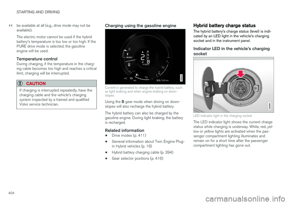
Current is generated to charge the hybrid battery, such as light braking and when engine braking on down-slopes
Using the
B gear mode when driving on down-
slopes will also recharge the hybrid battery. The hybrid battery can also be charged by the gasoline engine. During light braking, the batteryis recharged.
Related information
• Drive modes (p. 411)
• General information about Twin Engine Plug-in Hybrid vehicles (p. 16)
• Hybrid battery charging cable (p. 394)
• Gear selector positions (p. 416)
Hybrid battery charge status The hybrid battery's charge status (level) is indi- cated by an LED light in the vehicle's chargingsocket and in the instrument panel.
Indicator LED in the vehicle's charging socket
LED indicator light in the charging socket
The LED indicator light shows the current charge status while charging is underway. White, red, yel-low or yellow lights are activated when the pas-senger compartment lighting illuminates andremain on for a short time after the passengercompartment lighting has gone out.
Page 408 of 580
STARTING AND DRIVING
406
GraphicMessageExplanation
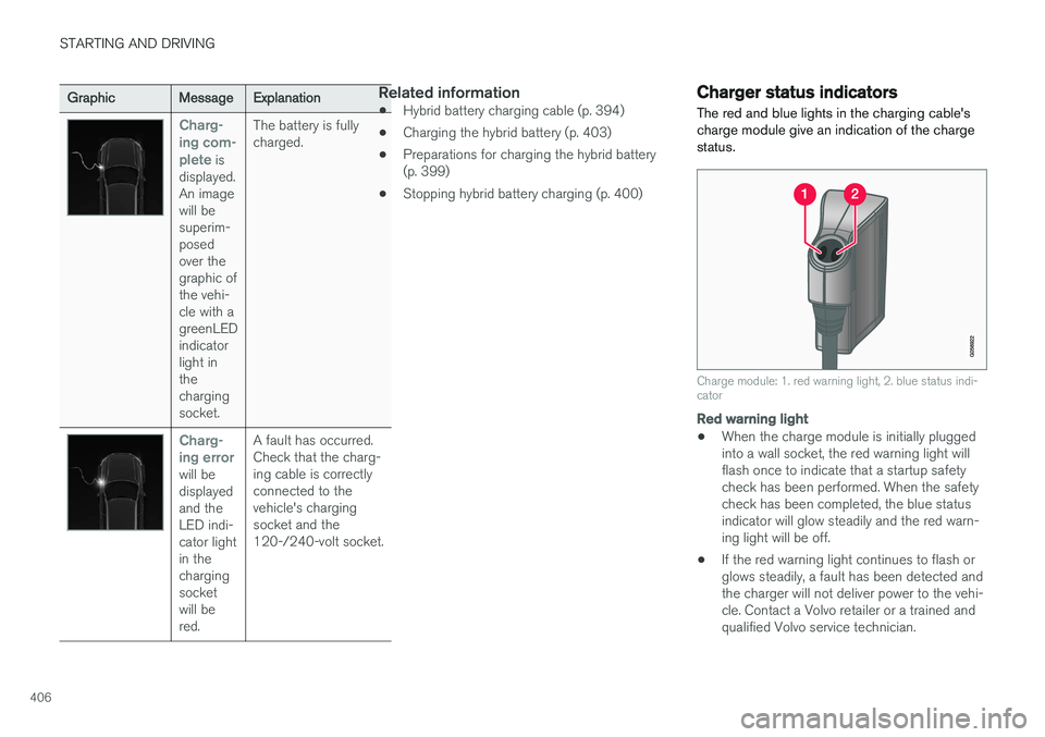
Charg- ing com-plete
is
displayed. An imagewill besuperim-posedover thegraphic ofthe vehi-cle with agreenLEDindicatorlight inthechargingsocket. The battery is fullycharged.
Charg- ing error
will be displayedand theLED indi-cator lightin thechargingsocketwill bered.
A fault has occurred.Check that the charg-ing cable is correctlyconnected to thevehicle's chargingsocket and the120-/240-volt socket.
Related information
•
Hybrid battery charging cable (p. 394)
• Charging the hybrid battery (p. 403)
• Preparations for charging the hybrid battery (p. 399)
• Stopping hybrid battery charging (p. 400)
Charger status indicators
The red and blue lights in the charging cable's charge module give an indication of the chargestatus.
Charge module: 1. red warning light, 2. blue status indi- cator
Red warning light
• When the charge module is initially plugged into a wall socket, the red warning light willflash once to indicate that a startup safetycheck has been performed. When the safetycheck has been completed, the blue statusindicator will glow steadily and the red warn-ing light will be off.
• If the red warning light continues to flash orglows steadily, a fault has been detected andthe charger will not deliver power to the vehi-cle. Contact a Volvo retailer or a trained andqualified Volvo service technician.
Page 479 of 580
WHEELS AND TIRES
477
Tire direction of rotation
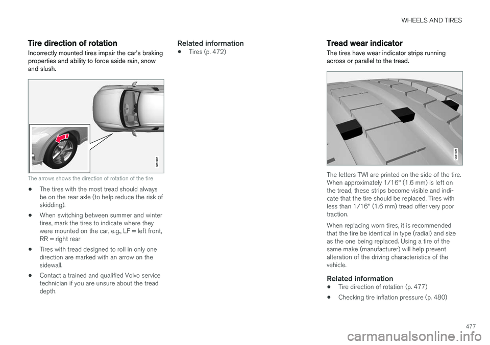
Incorrectly mounted tires impair the car's braking properties and ability to force aside rain, snowand slush.
The arrows shows the direction of rotation of the tire
• The tires with the most tread should always be on the rear axle (to help reduce the risk ofskidding).
• When switching between summer and wintertires, mark the tires to indicate where theywere mounted on the car, e.g., LF = left front,RR = right rear
• Tires with tread designed to roll in only onedirection are marked with an arrow on thesidewall.
• Contact a trained and qualified Volvo servicetechnician if you are unsure about the treaddepth.
Related information
•Tires (p. 472)
Tread wear indicator
The tires have wear indicator strips running across or parallel to the tread.
The letters TWI are printed on the side of the tire. When approximately 1/16" (1.6 mm) is left onthe tread, these strips become visible and indi-cate that the tire should be replaced. Tires withless than 1/16" (1.6 mm) tread offer very poortraction. When replacing worn tires, it is recommended that the tire be identical in type (radial) and sizeas the one being replaced. Using a tire of thesame make (manufacturer) will help preventalteration of the driving characteristics of thevehicle.
Related information
• Tire direction of rotation (p. 477)
• Checking tire inflation pressure (p. 480)
Page 488 of 580
||
WHEELS AND TIRES
486the inflation pressure recommended by the vehi- cle manufacturer on the vehicle placard or tireinflation pressure label. (If your vehicle has tiresof a different size than the size indicated on thevehicle placard or tire inflation pressure label, youshould determine the proper tire inflation pres-sure for those tires.) As an added safety feature, your vehicle has been equipped with a tire pressure monitoringsystem (TPMS) that illuminates a low tire pres-sure telltale when one or more of your tires issignificantly under-inflated. Accordingly, when thelow tire pressure telltale illuminates, you shouldstop and check your tires as soon as possible,and inflate them to the proper pressure. Driving on a significantly under-inflated tire cau- ses the tire to overheat and can lead to tire fail-ure. Under-inflation also reduces fuel efficiencyand tire tread life, and may affect the vehicle'shandling and stopping ability. Please note thatthe TPMS is not a substitute for proper tire main-tenance, and it is the driver's responsibility tomaintain correct tire pressure, even if under-infla-tion has not reached the level to trigger illumina-tion of the TPMS low tire pressure telltale. Your vehicle has also been equipped with a TPMS malfunction indicator to indicate when thesystem is not operating properly. The TPMS mal-function indicator is combined with the low tirepressure telltale.
When the system detects a malfunction, the tell-tale will flash for approximately one minute andthen remain continuously illuminated. Thissequence will continue upon subsequent vehiclestart-ups as long as the malfunction exists. Whenthe malfunction indicator is illuminated, the sys-tem may not be able to detect or signal low tirepressure as intended. TPMS malfunctions may occur for a variety of reasons, including the installation of replacementor alternate tires or wheels on the vehicle thatprevent the TPMS from functioning properly.Always check the TPMS malfunction telltale afterreplacing one or more tires or wheels on yourvehicle to ensure that the replacement or alter-nate tires and wheels allow the TPMS to con-tinue to function properly.
Messages in the instrument panel
When the TPMS symbol illuminates, the following text messages may also be displayed:
•
Tire pressure low
•Tire pressure system Temporarily
unavailable
•Tire pressure system Service required
If TPMS cannot determine which tire(s) have low inflation pressure:
• All four tires will be shown as affected in thecenter display After changing wheels, always calibrate the sys-tem to avoid false warnings. TPMS does not replace the need for regular tire inspection and maintenance.
NOTE
If you change to tires with a different dimen- sion than the factory-installed ones, theTPMS system must be calibrated for thesetires. TPMS cannot be turned off.
WARNING
Incorrect inflation pressure could lead to tire failure, resulting in a loss of control of thevehicle.
Related information
•
Checking tire inflation pressure (p. 487)
• Reinflating tires equipped with the Tire Pressure Monitoring System (TPMS)(p. 488)
• Ignition modes (p. 389)