warning VOLVO XC90 TWIN ENGINE 2020 Owners Manual
[x] Cancel search | Manufacturer: VOLVO, Model Year: 2020, Model line: XC90 TWIN ENGINE, Model: VOLVO XC90 TWIN ENGINE 2020Pages: 693, PDF Size: 13.34 MB
Page 447 of 693

STARTING AND DRIVING
445
Hill Descent Control
The function for assisting when driving down- hill (HDC 12
) is a low-speed function with
increased engine braking. The function makes it possible to increase or decrease thevehicle's speed on steep downhill gradientsby only using the accelerator pedal, withoutapplying the brakes. The function is included in the
Off Road drive
mode.
HDC is designed for driving on rough roads at low speeds and downhill gradients with slip-pery or otherwise difficult road surfaces. Thedriver does not need to use the brake pedalbut can instead focus on steering.
WARNING
HDC is only intended to be a supplemen- tary braking aid and it does not function inall situations. The driver is always ultimately responsible for operating the vehicle in a safe manner.
FunctionHill Descent Control allows the vehicle to move forward or backward at very low speedsassisted by the brake system. The driver canincrease the speed by pressing the acceleratorpedal. When the accelerator pedal is released, the vehicle will return to very low speedregardless of how steep the hill is and withoutthe brakes needing to be applied. The brakelights will illuminate when the function is acti-vated. The driver can brake to stop or slow the vehi- cle at any time by depressing the brake pedal. HDC is activated along with Low Speed Con- trol (LSC
13
), which facilitates and improves
traction and control on rough and slippery sur- faces. The system is intended to be used atlow speeds, up to approximately 40 km/h (25mph).
To keep in mind when using HDC
If the function is switched off while drivingon a steep downhill gradient, brakingeffect will be gradually reduced.
HDC can be used in gear positions
D and
R , and in manual gears 1 or 2.
It is not possible to manually shift to thirdgear or higher when HDC is active.
NOTE
When LSC with HDC is activated in theOff Road drive mode, the feel of the accel-
erator pedal and engine response will change.
NOTE
This drive mode is not designed to be used for normal street driving.
NOTE
The function is deactivated when driving at high speeds and must be reactivated atlower speeds if so desired.
Related information
Activating and deactivating Hill Descent Control using the function button (p. 446)
Changing drive mode (p. 438)
Low Speed Control (p. 443)
All Wheel Drive (AWD) (p. 431)
12
Hill Descent Control
13 Low Speed Control
Page 456 of 693
||
STARTING AND DRIVING
4544. Avoid overfilling the tank. Do not press the
handle on the filler nozzle again after it has initially stopped pumping.
> The fuel tank is now filled.
NOTE
An over-full tank may overflow in hot weather.
CAUTION
Avoid spilling gasoline during refueling. In addition to causing damage to the environ-ment, gasolines containing alcohol cancause damage to painted surfaces, whichmay not be covered under the New VehicleLimited Warranty.
Refueling from a fuel containerWhen filling from a fuel container, use the fun- nel provided in a foam block under the floorhatch in the cargo compartment.
1. Open the fuel filler door.
2. Insert the funnel into the fuel filler pipe'sopening. There are two flaps just inside the fuel filler pipe and the tube section ofthe funnel must push both of these flapsopen before fuel can be added.
WARNING
California Proposition 65 Operating, servicing and maintaining a pas- senger vehicle can expose you to chemi-cals including engine exhaust, carbon mon-oxide, phthalates, and lead, which areknown to the State of California to causecancer and birth defects or other reproduc-tive harm. To minimize exposure, avoidbreathing exhaust, do not idle the engineexcept as necessary, service your vehicle ina well ventilated area and wear gloves orwash your hands frequently when servicingyour vehicle. For more information go towww.P65Warnings.ca.gov/passenger-vehicle.
Related information
Opening/closing the fuel filler door (p. 452)
Fuel (p. 454)
Fuel
Volvo recommends the use of detergent gas- oline to control engine deposits.
Deposit control gasoline (gasoline with detergent additives)
Detergent gasoline is effective in keeping injectors and intake valves clean. Consistentuse of deposit control gasolines will helpensure good driveability and fuel economy. Ifyou are not sure whether the gasoline containsdeposit control additives, check with the serv-ice station operator.
NOTE
Volvo recommends not using external fuel injector cleaning systems, e.g. do not adddetergent additives to gasoline before orafter refueling.
Unleaded fuelAll Volvo vehicles have a three-way catalytic converter and must only use unleaded gaso-line. US and Canadian regulations require thatpumps delivering unleaded gasoline arelabeled "UNLEADED". Only the nozzles ofthese pumps will fit in your vehicle's fuel fillerinlet. It is unlawful to dispense leaded fuel intoa vehicle labeled "unleaded gasoline only".Leaded gasoline damages the three-way cata-lytic converter and the heated oxygen sensor
Page 459 of 693
STARTING AND DRIVING
457
WARNING
Never carry a cell phone that is switched
on while refueling your vehicle. If the
phone rings, this may cause a spark that could ignite gasoline fumes, resulting in fireand injury.
WARNING
Carbon monoxide is a poisonous, colorless, and odorless gas. It is present in all exhaustgases. If you ever smell exhaust fumesinside the vehicle, make sure the passengercompartment is ventilated, and immedi-ately return the vehicle to a trained andqualified Volvo service technician for cor-rection.
Demanding drivingIn demanding driving conditions, such as when towing a trailer or driving in hot weatheror for prolonged periods at high altitudes, itmay be a good idea to switch to a higher- octane fuel (AKI 14
91 or higher) or to switch to
another brand of gasoline in order to fully uti- lize the vehicle's engine capacity and optimizetraction.
Related information
Fuel (p. 454)
Emission controls (p. 457)
Emission controls
Three-way catalytic converter
Keep your engine properly tuned. Certain engine malfunctions, particularly involvingthe electrical, fuel or distributor ignitionsystems, may cause unusually high three-way catalytic converter temperatures. Donot continue to operate your vehicle if youdetect engine misfire, noticeable loss ofpower or other unusual operating condi-tions, such as engine overheating or back-firing. A properly tuned engine will helpavoid malfunctions that could damage thethree-way catalytic converter.
Do not park your vehicle over combustiblematerials, such as grass or leaves, whichcan come into contact with the hotexhaust system and cause such materialsto ignite under certain wind and weatherconditions.
Excessive starter cranking (in excess ofone minute), or an intermittently firing orflooded engine can cause three-way cata-lytic converter or exhaust system over-heating.
Remember that tampering or unauthor-ized modifications to the engine, theEngine Control Module, or the vehicle maybe illegal and can cause three-way cata-lytic converter or exhaust system over- heating. This includes: altering fuel injec-tion settings or components, alteringemission system components or locationor removing components, and/or repeateduse of leaded fuel.
NOTE
Unleaded fuel is required for vehicles with three-way catalytic converters.
Heated oxygen sensorsThe heated oxygen sensors monitor the oxy- gen content of the exhaust gases. Readingsare fed into a control module that continuouslymonitors engine functions and controls fuelinjection. The ratio of fuel to air into the engineis continuously adjusted for efficient combus-tion to help reduce harmful emissions.
Related information
Octane rating (p. 455)
Fuel (p. 454)
14
AKI (Anti Knock Index) is an average value of RON (Research Octane Number) and MON (Motor Octane Number) - (RON)+(MON)/2
Page 460 of 693
STARTING AND DRIVING
458
Overheating of engine and transmission
In certain driving conditions, such as driving in mountainous areas or hot weather, there isa risk of the engine or transmission overheat-ing, especially when carrying heavy loads.
Engine power may be temporarily limited.
Remove any auxiliary lights mounted in front of the grille when driving in hotweather.
If the temperature in the engine's coolingsystem becomes too high, a warning sym-bol will appear in the instrument panel along with the message
Engine
temperature High temperature Stop
safely. Pull over to a safe location and let
the engine idle for a few minutes to cool down.
If the message
Engine temperature
High temperature Turn off engine orEngine coolant Level low, turn off
engine is displayed, stop the vehicle and
turn off the engine.
If the transmission begins to overheat, an alternative gear shifting program will beselected. An integrated protective functionwill also be activated, the warning symbolwill illuminate and the message
Transmission warm Reduce speed to
lower temperature or Transmission hot
Stop safely, wait for cooling will be dis- played in the instrument panel. Follow the recommendations given by reducingspeed or stopping the vehicle safely andletting the engine idle for a few minutes tolet the transmission cool.
If the vehicle begins to overheat, the airconditioning may be temporarily switchedoff.
After a prolonged period of driving indemanding conditions, do not turn off theengine immediately after stopping.
NOTE
It is normal for the engine's cooling fan to operate for a short time after the engine isswitched off.
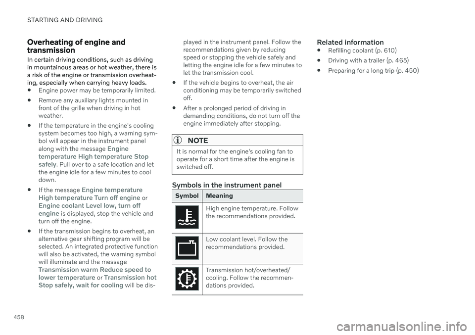
Symbols in the instrument panel
Symbol Meaning
High engine temperature. Follow the recommendations provided.
Low coolant level. Follow the recommendations provided.
Transmission hot/overheated/ cooling. Follow the recommen-dations provided.
Related information
Refilling coolant (p. 610)
Driving with a trailer (p. 465)
Preparing for a long trip (p. 450)
Page 462 of 693
||
STARTING AND DRIVING
4601. Put the ignition in mode
0.
2. Make sure the auxiliary battery (the bat- tery used to jump start the discharged battery) has a voltage of 12 volts.
3. If the auxiliary battery is in another vehicle, turn off that vehicle's engine and makesure that the vehicles are not touchingeach other.
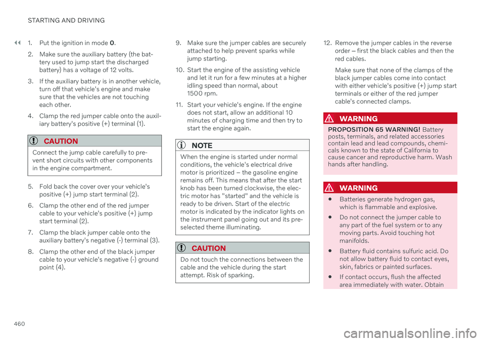
4. Clamp the red jumper cable onto the auxil- iary battery's positive (+) terminal (1).
CAUTION
Connect the jump cable carefully to pre- vent short circuits with other componentsin the engine compartment.
5. Fold back the cover over your vehicle's positive (+) jump start terminal (2).
6. Clamp the other end of the red jumper cable to your vehicle's positive (+) jump start terminal (2).
7. Clamp the black jumper cable onto the auxiliary battery's negative (-) terminal (3).
8. Clamp the other end of the black jumper cable to your vehicle's negative (-) groundpoint (4). 9. Make sure the jumper cables are securely
attached to help prevent sparks whilejump starting.
10. Start the engine of the assisting vehicle and let it run for a few minutes at a higheridling speed than normal, about1500 rpm.
11. Start your vehicle's engine. If the engine does not start, allow an additional 10minutes of charging time and then try tostart the engine again.
NOTE
When the engine is started under normal conditions, the vehicle's electrical drivemotor is prioritized – the gasoline engineremains off. This means that after the startknob has been turned clockwise, the elec-tric motor has "started" and the vehicle isready to be driven. Start of the electricmotor is indicated by the indicator lights onthe instrument panel going out and its pre-selected theme illuminating.
CAUTION
Do not touch the connections between the cable and the vehicle during the startattempt. Risk of sparking.
12. Remove the jumper cables in the reverseorder ‒ first the black cables and then the
red cables. Make sure that none of the clamps of the black jumper cables come into contactwith either vehicle's positive (+) jump startterminals or either of the red jumpercable's connected clamps.
WARNING
PROPOSITION 65 WARNING! Battery
posts, terminals, and related accessories contain lead and lead compounds, chemi-cals known to the state of California tocause cancer and reproductive harm. Washhands after handling.
WARNING
Batteries generate hydrogen gas, which is flammable and explosive.
Do not connect the jumper cable toany part of the fuel system or to anymoving parts. Avoid touching hotmanifolds.
Battery fluid contains sulfuric acid. Donot allow battery fluid to contact eyes,skin, fabrics or painted surfaces.
If contact occurs, flush the affectedarea immediately with water. Obtain
Page 466 of 693

||
STARTING AND DRIVING
* Option/accessory.
464
Installing the ball holder1. If necessary, remove the cotter pin from
the locking bolt and slide the locking bolt out of the towbar assembly.
2. Slide the ball holder into the towbar assembly.
3. Align the hole in the ball holder with the one in the towbar assembly.
4. Slide the locking bolt through the towbar assembly/ball holder.
5. Insert the cotter pin in the hole at the end of the locking bolt.
WARNING
Be sure the towbar is securely locked in position before attaching anything toit.
Always attach the trailer's safety wiresecurely to the towbar's safety wireattachment bracket.
Removing the ball holder1. Remove the cotter pin from the locking
bolt and slide the locking bolt out of theball holder/towbar assembly.
2. Pull the ball holder out of the towbar assembly.
WARNING
Damage may occur on the towbar if it is not used correctly or if incorrect or faultyaccessories are used, such as:
Overloading of accessory.
Use of incorrect or faulty accessory.
Accessory used for an incorrect pur- pose.
Use of weight-distributing towing sys-tem.
Incorrectly positioned ball mount; seegeometric limits for the towbar.
Stowing the ball holder
WARNING
When not in use, the detachable ball holder should always be properly stowed in thedesignated location under the floor of thecargo compartment.
Driving with a trailerWhen towing a trailer, the original ball holder or equivalent should be used.
The ball mount must fall within the geometric limits for the towbar, for both distance
and
height
. Geometric limits are described on a
type plate located on the towbar.
Related information
Retractable hitch
* (p. 461)
Driving with a trailer (p. 465)
Towing capacity and tongue weight (p. 667)
Page 468 of 693
||
STARTING AND DRIVING
* Option/accessory.
466
NOTE
Extreme weather conditions, towing a trailer, high altitude and lower fuel gradethan recommended are factors that cansignificantly increase the vehicle's fuel con-sumption.
Trailer weights
WARNING
Please adhere to the recommendations provided for trailer weight. If the recom-mendations are not followed, the vehicleand trailer may be difficult to control duringevasive maneuvers and braking.
NOTE
The specified maximum trailer weights are those permitted by Volvo. National vehicleregulations may set additional restrictionson trailer weight and speed. The trailerhitches may be certified for higher towingweights than the vehicle is permitted totow.
Self-leveling suspension *The vehicle's self-leveling system attempts to keep the vehicle at a constant level, regardlessof load (up to the maximum permitted weight).When the vehicle is stationary, the rear end of the vehicle will be slightly lowered, which isnormal.
Driving in hilly terrain or hot weatherIn certain conditions, there is a risk of over-heating when driving with a trailer. If overheat-ing of the engine and drive system is detected,a warning symbol will illuminate in the instru-ment panel and a message will appear. The automatic transmission selects the opti- mal gear for the current load and enginespeed.
Steep inclines
Do not lock the automatic transmission into a higher gear than what the engine can handle
‒
it is not always preferable to drive in highgears at low rpm.
Parking on a hill
1. Depress the brake pedal.
2. Apply the parking brake.
3. Put the gear selector in P.
4. Release the brake pedal.Put chocks behind the wheels when the vehi- cle is parked on a hill with a trailer attached.
Starting on a hill
1. Depress the brake pedal.
2. Put the gear selector in D.
3. Release the parking brake.
4. Release the brake pedal and start driving.
Related information
Trailer Stability Assist
* (p. 467)
Checking trailer lights (p. 468)
Towing capacity and tongue weight (p. 667)
Overheating of engine and transmission(p. 458)
Retractable hitch
* (p. 461)
Page 471 of 693
STARTING AND DRIVING
}}
469
Towing using a towline
This section refers to one vehicle being towed behind another using a towline.
Never attempt to tow a Twin Engine vehicle behind another vehicle as this could damagethe electric motor. The vehicle must instead belifted onto a tow truck and transported with allfour wheels on the bed or lifting platform ofthe truck (no wheels may touch the road).
Towing another vehicleTowing another vehicle requires a lot of power - use the Constant AWD drive mode. This
helps charge the hybrid battery and improve the vehicle's driving and roadholding characte-ristics. Before towing another vehicle, check applica- ble speed limit regulations.
Jump startingNever attempt to tow the vehicle to start theengine, as this could damage the electricmotor. Use an auxiliary battery if the start bat-tery's charge level is so low that the enginecannot be started.
CAUTION
Attempts to tow-start the vehicle could cause damage to the electrical drive motorand three-way catalytic converter.
Related information
Attaching and removing the towing eyelet (p. 469)
Hazard warning flashers (p. 164)
Recovery (p. 470)
Jump starting using another battery(p. 459)
Selecting ignition mode (p. 416)
Transmission (p. 426)
Attaching and removing the towing eyelet
Use the towing eyelet to tow another vehicle. Screw the towing eyelet securely into placein the threaded outlet behind the cover on theright-hand side of the rear bumper.
NOTE
If the vehicle is equipped with a towbar, there is no rear attachment for the towingeye.
Attaching the towing eyelet
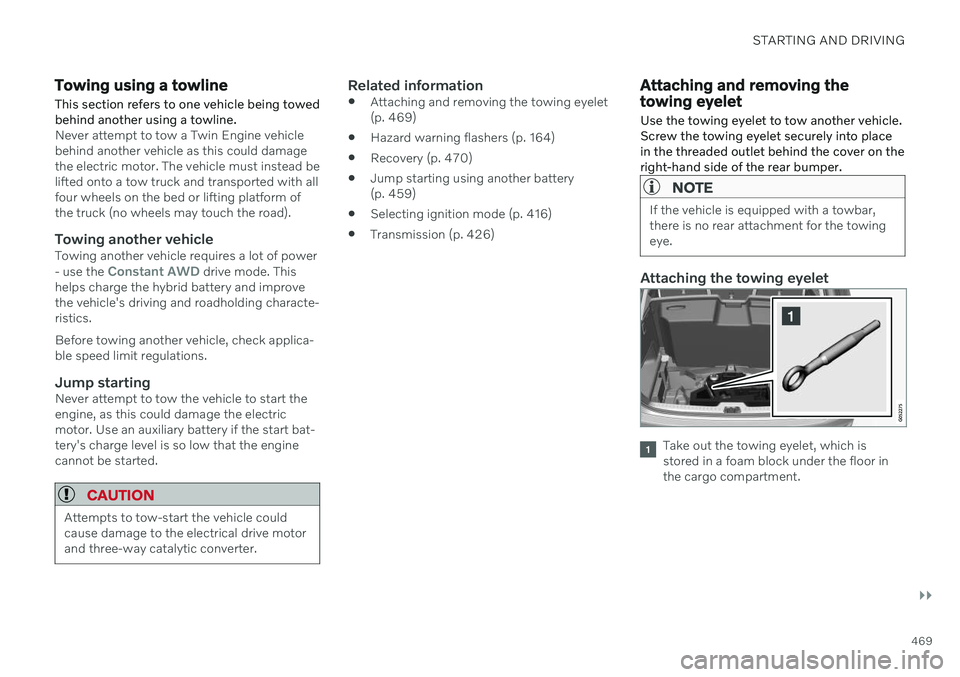
Take out the towing eyelet, which is stored in a foam block under the floor inthe cargo compartment.
Page 473 of 693
STARTING AND DRIVING
* Option/accessory.471
only be lifted with the tow truck's lifting equip- ment.
WARNING
No person or object should be behind the tow truck when the vehicle is lifted ontothe bed of the truck.
Related information
Attaching and removing the towing eyelet (p. 469)
HomeLink ®
*18
HomeLink ®
19
is a programmable remote con-
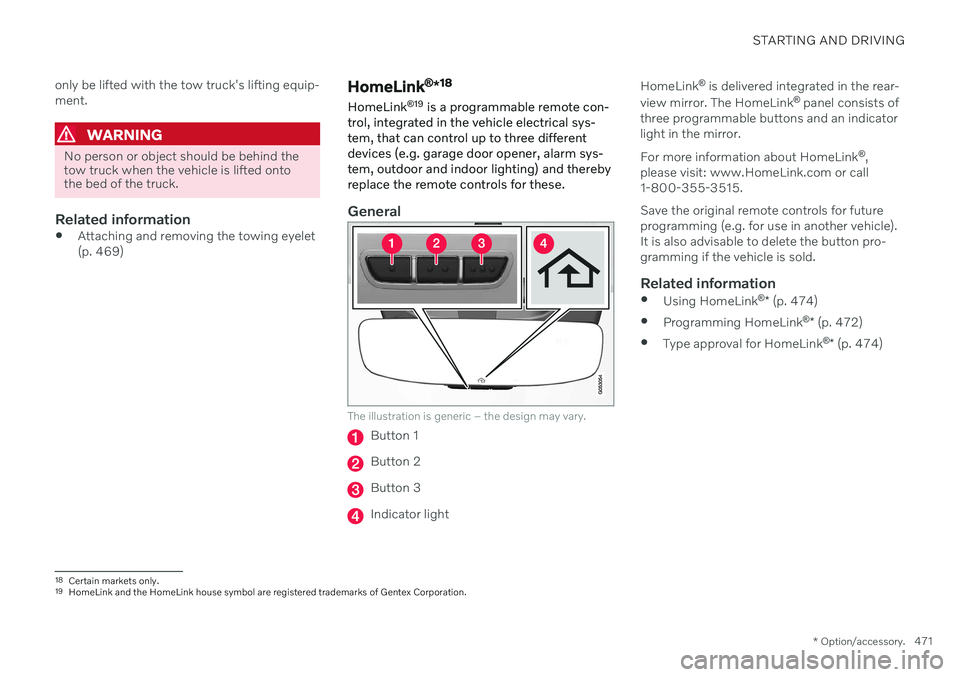
trol, integrated in the vehicle electrical sys- tem, that can control up to three differentdevices (e.g. garage door opener, alarm sys-tem, outdoor and indoor lighting) and therebyreplace the remote controls for these.
General
The illustration is generic – the design may vary.
Button 1
Button 2
Button 3
Indicator light HomeLink
®
is delivered integrated in the rear-
view mirror. The HomeLink ®
panel consists of
three programmable buttons and an indicator light in the mirror. For more information about HomeLink ®
,
please visit: www.HomeLink.com or call 1-800-355-3515. Save the original remote controls for future programming (e.g. for use in another vehicle).It is also advisable to delete the button pro-gramming if the vehicle is sold.
Related information
Using HomeLink ®
* (p. 474)
Programming HomeLink ®
* (p. 472)
Type approval for HomeLink ®
* (p. 474)
18
Certain markets only.
19 HomeLink and the HomeLink house symbol are registered trademarks of Gentex Corporation.
Page 474 of 693
STARTING AND DRIVING
* Option/accessory.
472
Programming HomeLink ®
*20
Follow these instructions to program HomeLink ®
, reset all programming, or pro-
gram individual buttons.
NOTE
In some vehicles, the ignition must be on or in the "accessory position" before HomeLink ®
can be programmed or used. It
can be a good idea to put new batteries in the remote control being replaced by HomeLink ®
for faster programming and
better radio signal transmission. TheHomeLink ®
buttons should be reset before
programming.
WARNING
While HomeLink ®
is being programmed,
the garage door or gate being programmed may be activated. Make sure that no one isnear the door or gate during programming.When programming a garage door opener,it is advised to park outside of the garage. 1. Point the remote control at the
HomeLink ®
button to be programmed and
hold it about 2-8 cm (1-3 inches) from the button. Do not obstruct the HomeLink ®
indicator light. Note: Some remote controls are more
effective at programming HomeLink ®
from
a distance of about 15-20 cm (6-12 inches). Keep this in mind if you experi-ence any programming difficulties.
2. Press and hold both the remote control button and the HomeLink ®
button to be
programmed. 3. Do not release the buttons until the indica-
tor light has stopped flashing slowly(about once a second) and either flashesquickly (about 10 times a second) orglows steadily. >If the indicator light glows steadily: Indication that programming is com-plete. Press the programmed buttontwice to activate. If the indicator light flashes quickly: The device being programmed with HomeLink ®
may have a security func-
tion that requires an extra step. Try pressing the programmed button twiceto see whether the programmingworks. Otherwise, continue with thefollowing steps.
20 Certain markets only.