YAMAHA AEROX50 2004 Owner's Manual
Manufacturer: YAMAHA, Model Year: 2004, Model line: AEROX50, Model: YAMAHA AEROX50 2004Pages: 84, PDF Size: 0.96 MB
Page 21 of 84
3
INSTRUMENT AND CONTROL FUNCTIONS
EAU00098
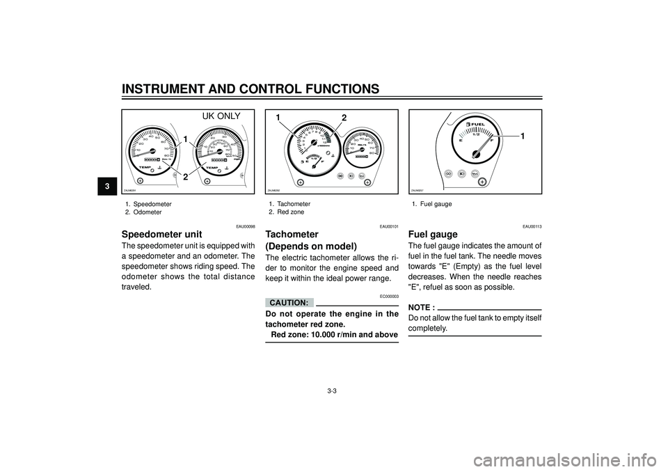
Speedometer unit
The speedometer unit is equipped with
a speedometer and an odometer. The
speedometer shows riding speed. The
odometer shows the total distance
traveled.
EAU00113
Fuel gauge
The fuel gauge indicates the amount of
fuel in the fuel tank. The needle moves
towards "E" (Empty) as the fuel level
decreases. When the needle reaches
"E", refuel as soon as possible.
NOTE :
Do not allow the fuel tank to empty itself
completely.
E1/2
F1
ZAUM0257
1. Speedometer
2. Odometer1. Fuel gauge
3-3
1
2
ZAUM0292M
1. Tachometer
2. Red zone
EAU00101
Tachometer
(Depends on model)
The electric tachometer allows the ri-
der to monitor the engine speed and
keep it within the ideal power range.
EC000003
Do not operate the engine in the
tachometer red zone.
Red zone: 10.000 r/min and above
CAUTION:
2
1
ZAUM0291M
UK ONLY
Page 22 of 84
INSTRUMENT AND CONTROL FUNCTIONS
3
EAU00118
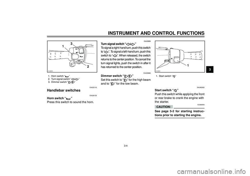
Handlebar switches
EAU03888
Dimmer switch “/”
Set this switch to “
” for the high beam
and to “
” for the low beam.
EAU03889
Turn signal switch “/”
To signal a right-hand turn, push this switch
to “
”. To signal a left-hand turn, push this
switch to “
”. When released, the switch
returns to the center position. To cancel the
turn signal lights, push the switch in after it
has returned to the center position.
EAU00129
Horn switch “”
Press this switch to sound the horn.
EAUM0063
Start switch “”
Push this switch while applying the front
or rear brake to crank the engine with
the starter.
EC000005
See page 5-2 for starting instruc-
tions prior to starting the engine.
1
2 3
ZAUM0258
1
ZAUM0261
1. Horn switch “”
2. Turn signal switch “/”
3. Dimmer switch “
/”
CAUTION:
1. Start switch “”
3-4
Page 23 of 84
3
INSTRUMENT AND CONTROL FUNCTIONS
EAU03882
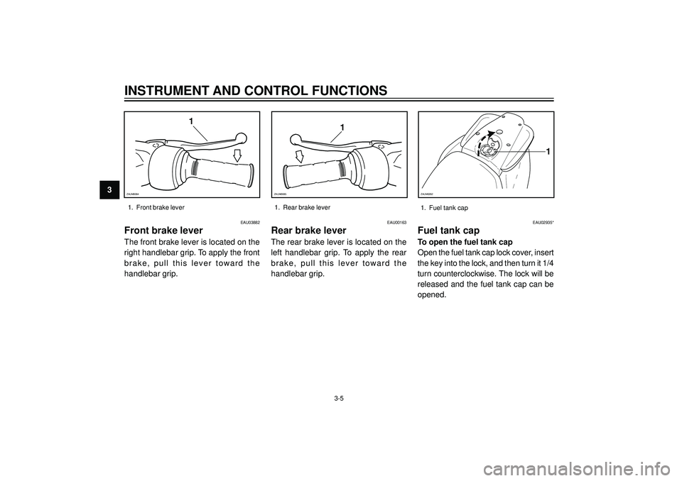
Front brake lever
The front brake lever is located on the
right handlebar grip. To apply the front
brake, pull this lever toward the
handlebar grip.
EAU00163
Rear brake lever
The rear brake lever is located on the
left handlebar grip. To apply the rear
brake, pull this lever toward the
handlebar grip.
1. Front brake lever 1. Rear brake lever
1
ZAUM0084
1
ZAUM0085
EAU02935*
Fuel tank cap
To open the fuel tank cap
Open the fuel tank cap lock cover, insert
the key into the lock, and then turn it 1/4
turn counterclockwise. The lock will be
released and the fuel tank cap can be
opened.
1
ZAUM0262
3-51. Fuel tank cap
Page 24 of 84
INSTRUMENT AND CONTROL FUNCTIONS
3 To close the fuel tank cap
1. Push the fuel tank cap into posi-
tion with the key inserted in the
lock.
2. Turn the key clockwise to the ori-
ginal position, remove it, and then
close the lock cover.
NOTE :
The fuel tank cap cannot be closed
unless the key is in the lock. In addi-
tion, the key cannot be removed if the
cap is not properly closed and locked.
EWA00025
Make sure that the fuel tank cap is
properly closed before riding.
WARNING
EAU03753
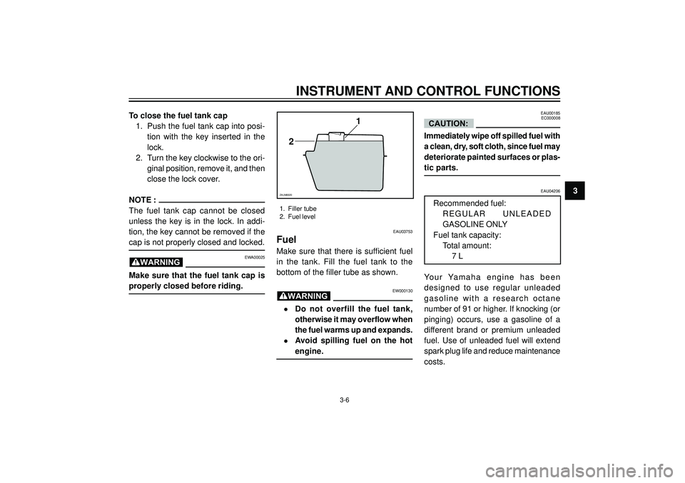
Fuel
Make sure that there is sufficient fuel
in the tank. Fill the fuel tank to the
bottom of the filler tube as shown.
EW000130
•Do not overfill the fuel tank,
otherwise it may overflow when
the fuel warms up and expands.
•Avoid spilling fuel on the hot
engine.
WARNING
1
2
ZAUM0020
1. Filler tube
2. Fuel level
EAU00185
EC000008
Immediately wipe off spilled fuel with
a clean, dry, soft cloth, since fuel may
deteriorate painted surfaces or plas-
tic parts.
CAUTION:
EAU04206
Recommended fuel:
REGULAR UNLEADED
GASOLINE ONLY
Fuel tank capacity:
Total amount:
7 L
Your Yamaha engine has been
designed to use regular unleaded
gasoline with a research octane
number of 91 or higher. If knocking (or
pinging) occurs, use a gasoline of a
different brand or premium unleaded
fuel. Use of unleaded fuel will extend
spark plug life and reduce maintenance
costs.
3-6
Page 25 of 84
3
INSTRUMENT AND CONTROL FUNCTIONS
EAU03098
Catalytic converter
This scooter is equipped with a catalytic
converter in the muffler.
EW000128
The exhaust system is hot after
operation. Make sure that the
exhaust system has cooled down
before doing any maintenance work.
EC000114
The following precautions must be
observed to prevent a fire hazard or
other damages.
•Use only unleaded gasoline.
The use of leaded gasoline will
cause unrepairable damage to
the catalytic converter.
•Never park the scooter near
possible fire hazards such as
grass or other materials that
easily burn.
•Do not allow the engine to idle
too long.
WARNING
CAUTION:
3-7
ZAUM0289M
EAUS0015
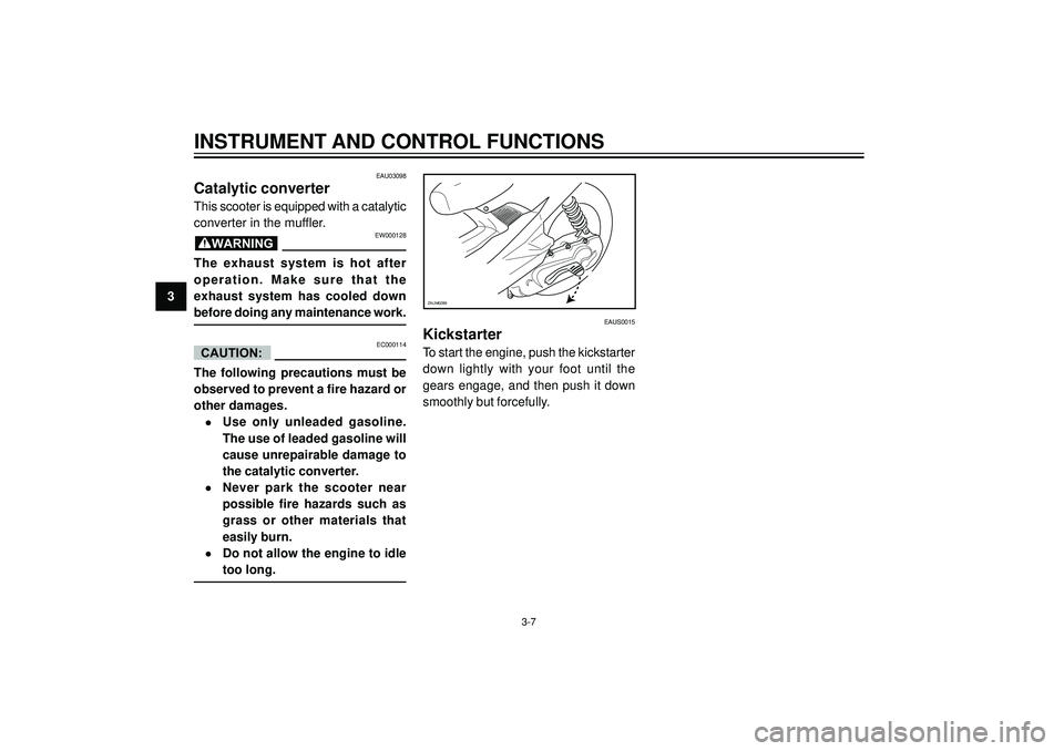
Kickstarter
To start the engine, push the kickstarter
down lightly with your foot until the
gears engage, and then push it down
smoothly but forcefully.
Page 26 of 84
INSTRUMENT AND CONTROL FUNCTIONS
3ZAUM0204
1
2
ZAUM0263
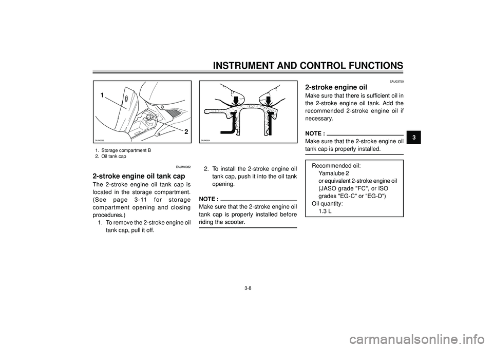
1. Storage compartment B
2. Oil tank cap
3-8
EAU03750
2-stroke engine oil
Make sure that there is sufficient oil in
the 2-stroke engine oil tank. Add the
recommended 2-stroke engine oil if
necessary.
NOTE :
Make sure that the 2-stroke engine oil
tank cap is properly installed.
Recommended oil:
Yamalube 2
or equivalent 2-stroke engine oil
(JASO grade "FC", or ISO
grades "EG-C" or "EG-D")
Oil quantity:
1.3 L
EAUM0082
2-stroke engine oil tank cap
The 2-stroke engine oil tank cap is
located in the storage compartment.
(See page 3-11 for storage
compartment opening and closing
procedures.)
1. To remove the 2-stroke engine oil
tank cap, pull it off.2. To install the 2-stroke engine oil
tank cap, push it into the oil tank
opening.
NOTE :
Make sure that the 2-stroke engine oil
tank cap is properly installed before
riding the scooter.
Page 27 of 84
3
INSTRUMENT AND CONTROL FUNCTIONS
EAU03091
Rider seat
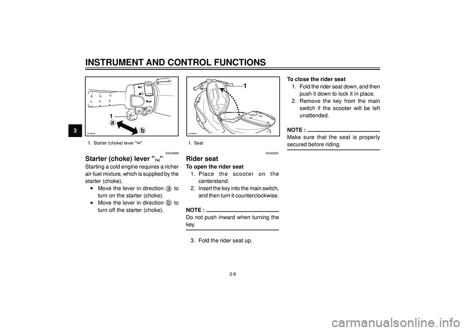
To open the rider seat
1. Place the scooter on the
centerstand.
2. Insert the key into the main switch,
and then turn it counterclockwise.
NOTE :
Do not push inward when turning the
key.
3. Fold the rider seat up.To close the rider seat
1. Fold the rider seat down, and then
push it down to lock it in place.
2. Remove the key from the main
switch if the scooter will be left
unattended.
NOTE :
Make sure that the seat is properly
secured before riding.
1
ZAUM0264
1. Seat
3-9
EAU03839
Starter (choke) lever ""
Starting a cold engine requires a richer
air-fuel mixture, which is supplied by the
starter (choke).
•Move the lever in direction a to
turn on the starter (choke).
•Move the lever in direction b to
turn off the starter (choke).
1. Starter (choke) lever ""
a
b
1
ZAUM0293
Page 28 of 84
INSTRUMENT AND CONTROL FUNCTIONS
3
1
ZAUM0265
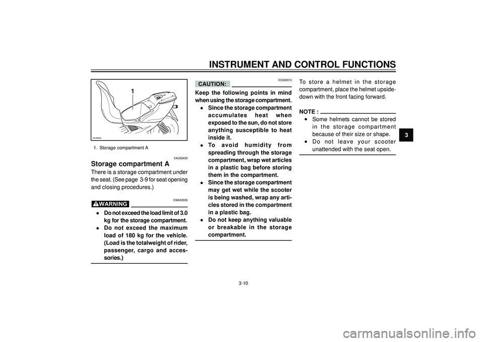
1. Storage compartment A
EAU03450
Storage compartment A
There is a storage compartment under
the seat. (See page 3-9 for seat opening
and closing procedures.)
EWA00005
•Do not exceed the load limit of 3.0
kg for the storage compartment.
•Do not exceed the maximum
load of 180 kg for the vehicle.
(Load is the totalweight of rider,
passenger, cargo and acces-
sories.)
EC000010
Keep the following points in mind
when using the storage compartment.
•Since the storage compartment
accumulates heat when
exposed to the sun, do not store
anything susceptible to heat
inside it.
•To avoid humidity from
spreading through the storage
compartment, wrap wet articles
in a plastic bag before storing
them in the compartment.
•Since the storage compartment
may get wet while the scooter
is being washed, wrap any arti-
cles stored in the compartment
in a plastic bag.
•Do not keep anything valuable
or breakable in the storage
compartment.To store a helmet in the storage
compartment, place the helmet upside-
down with the front facing forward.
NOTE :
•Some helmets cannot be stored
in the storage compartment
because of their size or shape.
•Do not leave your scooter
unattended with the seat open.
CAUTION:
WARNING
3-10
Page 29 of 84
3
INSTRUMENT AND CONTROL FUNCTIONS
a
1
ZAUM0266
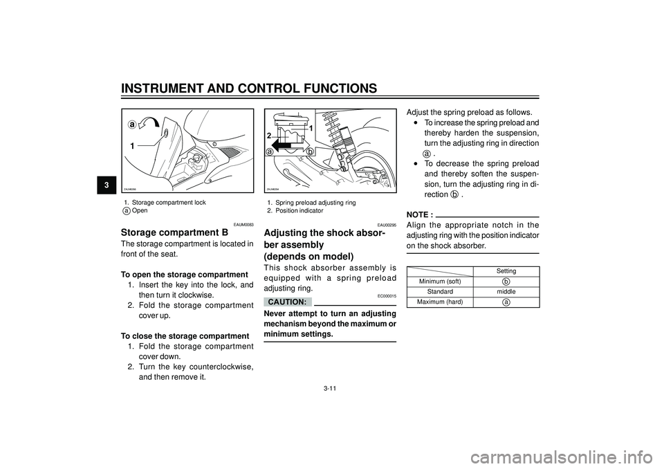
1. Storage compartment lock
a Open
3-11
ba
12
ZAUM0294
EAU00295
Adjusting the shock absor-
ber assembly
(depends on model)
This shock absorber assembly is
equipped with a spring preload
adjusting ring.
EC000015
Never attempt to turn an adjusting
mechanism beyond the maximum or
minimum settings.Adjust the spring preload as follows.
•To increase the spring preload and
thereby harden the suspension,
turn the adjusting ring in direction
a .
•To decrease the spring preload
and thereby soften the suspen-
sion, turn the adjusting ring in di-
rection b .
NOTE :
Align the appropriate notch in the
adjusting ring with the position indicator
on the shock absorber.
CAUTION:
Setting
Minimum (soft)
b
Standardmiddle
Maximum (hard)a
1. Spring preload adjusting ring
2. Position indicator
EAUM0083
Storage compartment B
The storage compartment is located in
front of the seat.
To open the storage compartment
1. Insert the key into the lock, and
then turn it clockwise.
2. Fold the storage compartment
cover up.
To close the storage compartment
1. Fold the storage compartment
cover down.
2. Turn the key counterclockwise,
and then remove it.
Page 30 of 84
INSTRUMENT AND CONTROL FUNCTIONS
3
EAU00315
EW000041
This shock absorber contains highly
pressurized nitrogen gas. For proper
handling, read and understand the
following information before
handling the shock absorber. The
manufacturer cannot be held
responsible for property damage or
personal injury that may result from
improper handling.
•Do not tamper with or attempt
to open the gas cylinder.
•Do not subject the shock absor-
ber to an open flame or other
high heat sources, otherwise it
may explode due to excessive
gas pressure.
•Do not deform or damage the
gas cylinder in any way, as this
will result in poor damping per-
formance.
•Always have a Yamaha dealer
service the shock absorber.
WARNING
3-12