lock YAMAHA AEROX50 2004 Owners Manual
[x] Cancel search | Manufacturer: YAMAHA, Model Year: 2004, Model line: AEROX50, Model: YAMAHA AEROX50 2004Pages: 84, PDF Size: 0.96 MB
Page 15 of 84

2
DESCRIPTION
Left view
1. Rear brake lever (page 3-5, 6-13, 6-16)
2. Left handlebar switches (page 3-4)
3. Speedometer (page 3-3)
4. Main switch/steering lock (page 3-1, 3-9)
2-1
1
23
4
68
7
5
5. Final transmission oil filler cap (page 6-7)
6. Centerstand (page 6-16)
7. Kick starter (page 3-7)
8. Air filter (page 6-9)
Page 18 of 84
EAU00027
INSTRUMENT AND CONTROL FUNCTIONS
Main switch / steering lock .................................................................. 3-1
Indicator and warning lights ................................................................ 3-2
Coolant temperature warning light ...................................................... 3-2
Speedometer unit ................................................................................ 3-3
Tachometer (depends on model) ........................................................ 3-3
Fuel gauge .......................................................................................... 3-3
Handlebar switches ............................................................................. 3-4
Front brake lever ................................................................................. 3-5
Rear brake lever .................................................................................. 3-5
Fuel tank cap ...................................................................................... 3-5
Fuel .....................................................................................................\o 3-6
Catalytic converter .............................................................................. 3-7
Kick starter .......................................................................................... 3-7
2-stroke engine oil tank cap ................................................................ 3-8
2-stroke engine oil ............................................................................... 3-8
Starter (choke) lever ............................................................................ 3-9
Rider seat ............................................................................................ 3-9
Storage compartment A .................................................................... 3-10
Storage compartment B .................................................................... 3-11
Adjusting the shock absorber assembly (depends on model) ........... 3-11
3
Page 19 of 84
3
INSTRUMENT AND CONTROL FUNCTIONS
EAU00029
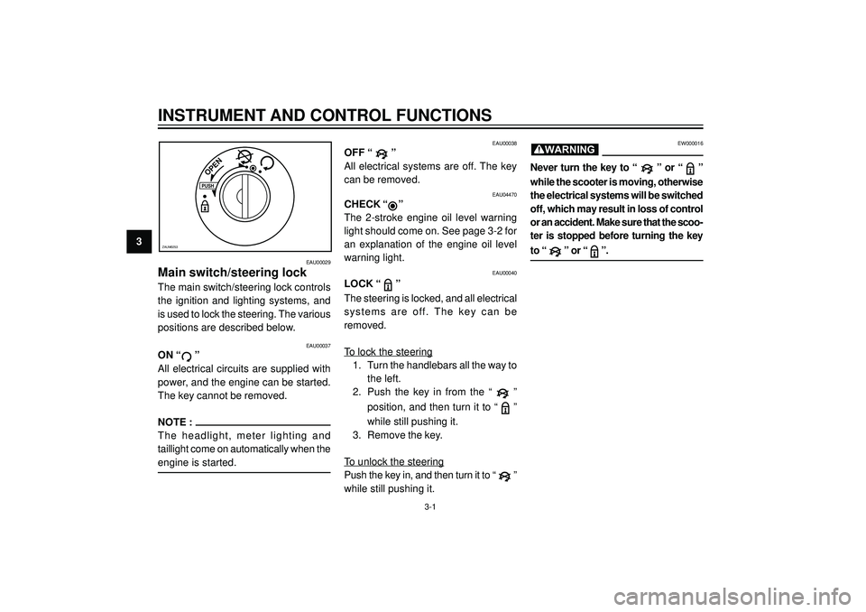
Main switch/steering lock
The main switch/steering lock controls
the ignition and lighting systems, and
is used to lock the steering. The various
positions are described below.
PUSH
OPEN
ZAUM0253
EAU00038
OFF “ ”
All electrical systems are off. The key
can be removed.
EAU04470
CHECK “”
The 2-stroke engine oil level warning
light should come on. See page 3-2 for
an explanation of the engine oil level
warning light.
EAU00040
LOCK “ ”
The steering is locked, and all electrical
systems are off. The key can be
removed.
To lock the steering
1. Turn the handlebars all the way to
the left.
2. Push the key in from the “
”
position, and then turn it to “
”
while still pushing it.
3. Remove the key.
To unlock the steering
Push the key in, and then turn it to “
”
while still pushing it.
EW000016
Never turn the key to “ ” or “ ”
while the scooter is moving, otherwise
the electrical systems will be switched
off, which may result in loss of control
or an accident. Make sure that the scoo-
ter is stopped before turning the key
to “ ” or “ ”.
WARNING
3-1
EAU00037
ON “ ”
All electrical circuits are supplied with
power, and the engine can be started.
The key cannot be removed.
NOTE :
The headlight, meter lighting and
taillight come on automatically when the
engine is started.
Page 23 of 84
3
INSTRUMENT AND CONTROL FUNCTIONS
EAU03882
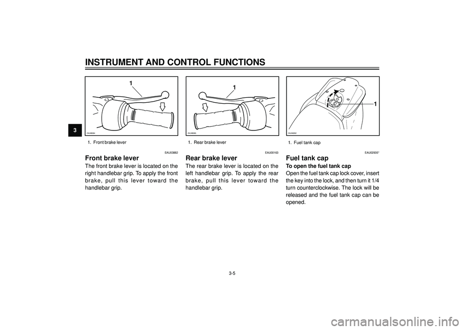
Front brake lever
The front brake lever is located on the
right handlebar grip. To apply the front
brake, pull this lever toward the
handlebar grip.
EAU00163
Rear brake lever
The rear brake lever is located on the
left handlebar grip. To apply the rear
brake, pull this lever toward the
handlebar grip.
1. Front brake lever 1. Rear brake lever
1
ZAUM0084
1
ZAUM0085
EAU02935*
Fuel tank cap
To open the fuel tank cap
Open the fuel tank cap lock cover, insert
the key into the lock, and then turn it 1/4
turn counterclockwise. The lock will be
released and the fuel tank cap can be
opened.
1
ZAUM0262
3-51. Fuel tank cap
Page 24 of 84
INSTRUMENT AND CONTROL FUNCTIONS
3 To close the fuel tank cap
1. Push the fuel tank cap into posi-
tion with the key inserted in the
lock.
2. Turn the key clockwise to the ori-
ginal position, remove it, and then
close the lock cover.
NOTE :
The fuel tank cap cannot be closed
unless the key is in the lock. In addi-
tion, the key cannot be removed if the
cap is not properly closed and locked.
EWA00025
Make sure that the fuel tank cap is
properly closed before riding.
WARNING
EAU03753
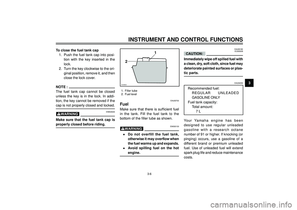
Fuel
Make sure that there is sufficient fuel
in the tank. Fill the fuel tank to the
bottom of the filler tube as shown.
EW000130
•Do not overfill the fuel tank,
otherwise it may overflow when
the fuel warms up and expands.
•Avoid spilling fuel on the hot
engine.
WARNING
1
2
ZAUM0020
1. Filler tube
2. Fuel level
EAU00185
EC000008
Immediately wipe off spilled fuel with
a clean, dry, soft cloth, since fuel may
deteriorate painted surfaces or plas-
tic parts.
CAUTION:
EAU04206
Recommended fuel:
REGULAR UNLEADED
GASOLINE ONLY
Fuel tank capacity:
Total amount:
7 L
Your Yamaha engine has been
designed to use regular unleaded
gasoline with a research octane
number of 91 or higher. If knocking (or
pinging) occurs, use a gasoline of a
different brand or premium unleaded
fuel. Use of unleaded fuel will extend
spark plug life and reduce maintenance
costs.
3-6
Page 27 of 84
3
INSTRUMENT AND CONTROL FUNCTIONS
EAU03091
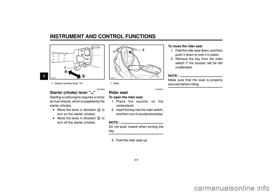
Rider seat
To open the rider seat
1. Place the scooter on the
centerstand.
2. Insert the key into the main switch,
and then turn it counterclockwise.
NOTE :
Do not push inward when turning the
key.
3. Fold the rider seat up.To close the rider seat
1. Fold the rider seat down, and then
push it down to lock it in place.
2. Remove the key from the main
switch if the scooter will be left
unattended.
NOTE :
Make sure that the seat is properly
secured before riding.
1
ZAUM0264
1. Seat
3-9
EAU03839
Starter (choke) lever ""
Starting a cold engine requires a richer
air-fuel mixture, which is supplied by the
starter (choke).
•Move the lever in direction a to
turn on the starter (choke).
•Move the lever in direction b to
turn off the starter (choke).
1. Starter (choke) lever ""
a
b
1
ZAUM0293
Page 29 of 84
3
INSTRUMENT AND CONTROL FUNCTIONS
a
1
ZAUM0266
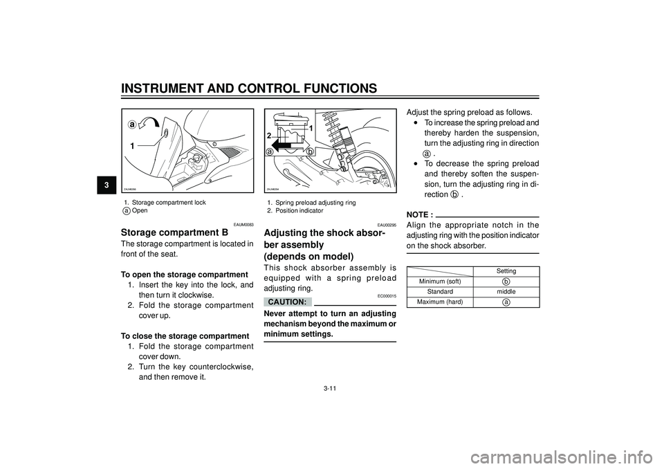
1. Storage compartment lock
a Open
3-11
ba
12
ZAUM0294
EAU00295
Adjusting the shock absor-
ber assembly
(depends on model)
This shock absorber assembly is
equipped with a spring preload
adjusting ring.
EC000015
Never attempt to turn an adjusting
mechanism beyond the maximum or
minimum settings.Adjust the spring preload as follows.
•To increase the spring preload and
thereby harden the suspension,
turn the adjusting ring in direction
a .
•To decrease the spring preload
and thereby soften the suspen-
sion, turn the adjusting ring in di-
rection b .
NOTE :
Align the appropriate notch in the
adjusting ring with the position indicator
on the shock absorber.
CAUTION:
Setting
Minimum (soft)
b
Standardmiddle
Maximum (hard)a
1. Spring preload adjusting ring
2. Position indicator
EAUM0083
Storage compartment B
The storage compartment is located in
front of the seat.
To open the storage compartment
1. Insert the key into the lock, and
then turn it clockwise.
2. Fold the storage compartment
cover up.
To close the storage compartment
1. Fold the storage compartment
cover down.
2. Turn the key counterclockwise,
and then remove it.
Page 57 of 84
PERIODIC MAINTENANCE AND MINOR REPAIR
6Observe these precautions:
•When checking the fluid level,
make sure that the top of the
master cylinder is level by turning
the handlebars.
•Use only the recommended
quality brake fluid, otherwise the
rubber seals may deteriorate,
causing leakage and poor braking
performance.
Recommended brake fluid:
DOT 4
NOTE :
If DOT 4 is not available, DOT 3 can be
used.
•Refill with the same type of brake
fluid. Mixing fluids may result in a
harmful chemical reaction and
lead to poor braking performance.
•Be careful that water does not
enter the master cylinder when
refilling. Water will significantly
lower the boiling point of the fluid
and may result in vapor lock.
•Brake fluid may deteriorate
painted surfaces or plastic parts.
Always clean up spilled fluid
immediately.
•As the brake pads wear, it is nor-
mal for the brake fluid level to
gradually go down. However, if the
brake fluid level goes down
suddenly, have a Yamaha dealer
check the cause.
EAUM0008*
Changing the brake fluid
Have a Yamaha dealer change the
brake fluid at the intervals specified in
the periodic maintenance and
lubrication chart. In addition, have the
brake hoses replaced every four years
or whenever there are damaged or
leaking.
6-15
EAU00774
Adjusting the Autolube pump
The Autolube pump is a vital and
sophisticated component of the engine,
which must be adjusted by a Yamaha
dealer at the intervals specified in the
periodic maintenance and lubrication
chart.
Page 62 of 84
PERIODIC MAINTENANCE AND MINOR REPAIR
6
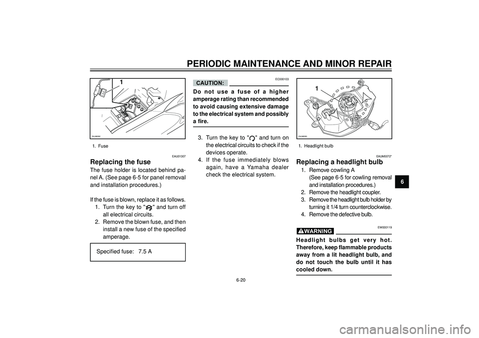
1
ZAUM0282
1. Fuse
EAU01307
Replacing the fuse
The fuse holder is located behind pa-
nel A. (See page 6-5 for panel removal
and installation procedures.)
If the fuse is blown, replace it as follows.
1. Turn the key to "
" and turn off
all electrical circuits.
2. Remove the blown fuse, and then
install a new fuse of the specified
amperage.
Specified fuse: 7.5 A
EC000103
Do not use a fuse of a higher
amperage rating than recommended
to avoid causing extensive damage
to the electrical system and possibly
a fire.
3. Turn the key to "
" and turn on
the electrical circuits to check if the
devices operate.
4. If the fuse immediately blows
again, have a Yamaha dealer
check the electrical system.
CAUTION:
EAUM0072*
Replacing a headlight bulb
1. Remove cowling A
(See page 6-5 for cowling removal
and installation procedures.)
2. Remove the headlight coupler.
3. Remove the headlight bulb holder by
turning it 1/4 turn counterclockwise.
4. Remove the defective bulb.
EW000119
Headlight bulbs get very hot.
Therefore, keep flammable products
away from a lit headlight bulb, and
do not touch the bulb until it has
cooled down.
1
ZAUM0283
1. Headlight bulb
WARNING
6-20
Page 63 of 84
PERIODIC MAINTENANCE AND MINOR REPAIR
65. Place a new headlight bulb into
position, and then secure it with
the bulb holder.
6. Connect the headlight coupler
and install the cowling A.
EC000105
Do not touch the glass part of the
headlight bulb to keep it free from
oil, otherwise the transparency of
the glass, the luminosity of the bulb,
and the bulb life will be adversely
affected. Thoroughly clean off any
dirt and fingerprints on the headlight
bulb using a cloth moistened with
alcohol or thinner.
CAUTION:
ZAUM0284
6-21
EAUM0037
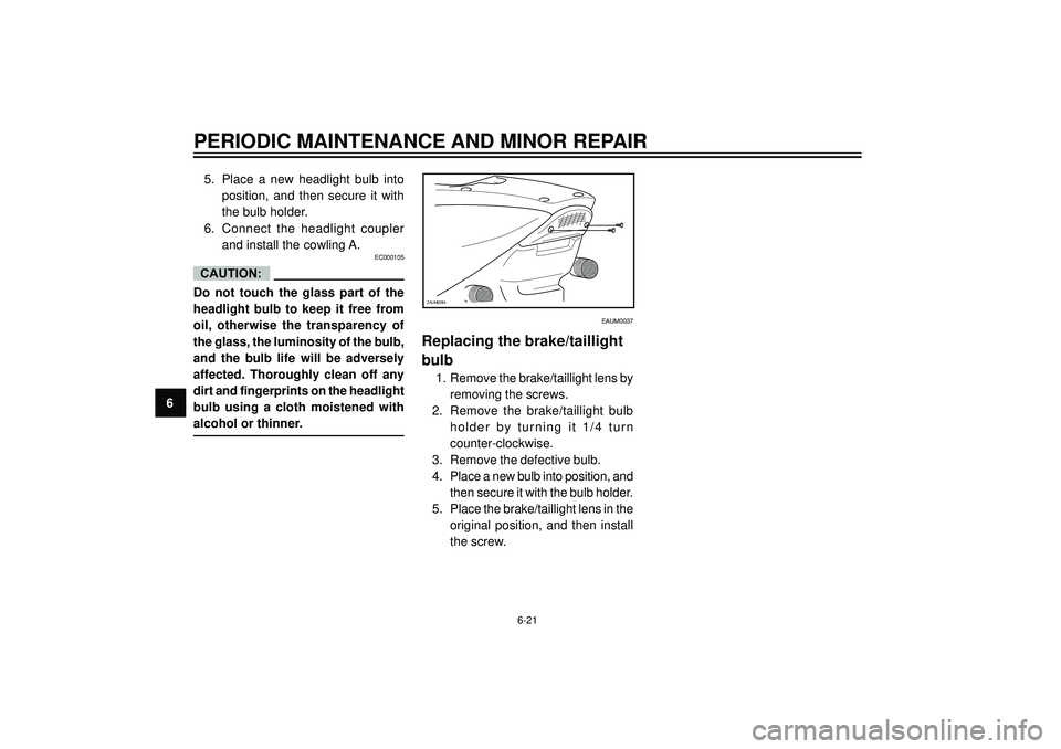
Replacing the brake/taillight
bulb
1. Remove the brake/taillight lens by
removing the screws.
2. Remove the brake/taillight bulb
holder by turning it 1/4 turn
counter-clockwise.
3. Remove the defective bulb.
4. Place a new bulb into position, and
then secure it with the bulb holder.
5. Place the brake/taillight lens in the
original position, and then install
the screw.