charging YAMAHA FJR1300A 2013 Owners Manual
[x] Cancel search | Manufacturer: YAMAHA, Model Year: 2013, Model line: FJR1300A, Model: YAMAHA FJR1300A 2013Pages: 118, PDF Size: 3.28 MB
Page 98 of 118

PERIODIC MAINTENANCE AND ADJUSTMENT
6-31
6
EAU39525
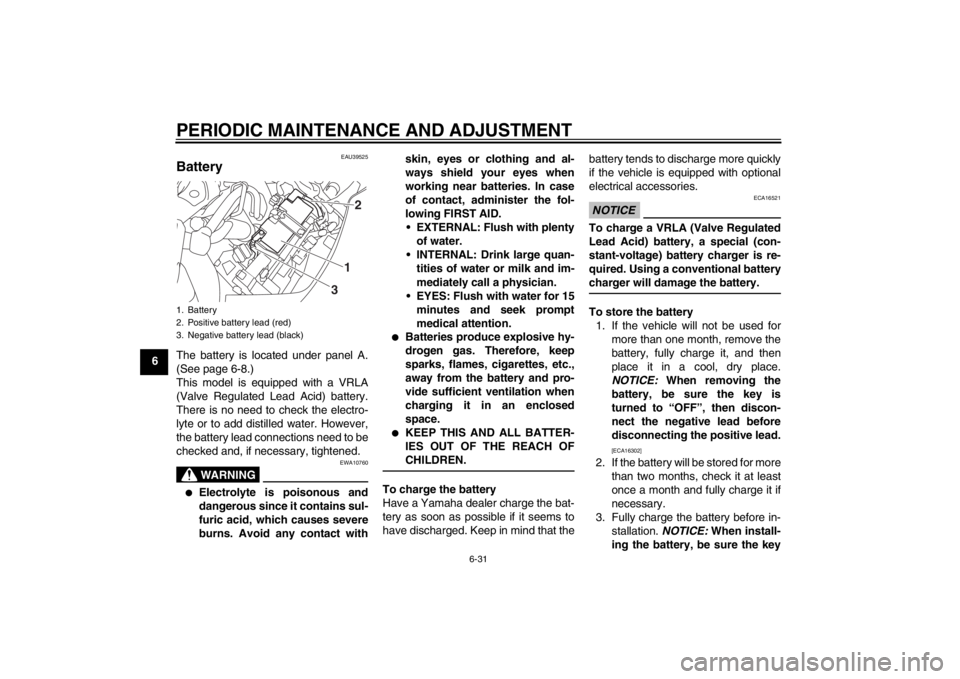
Battery The battery is located under panel A.
(See page 6-8.)
This model is equipped with a VRLA
(Valve Regulated Lead Acid) battery.
There is no need to check the electro-
lyte or to add distilled water. However,
the battery lead connections need to be
checked and, if necessary, tightened.
WARNING
EWA10760
●
Electrolyte is poisonous and
dangerous since it contains sul-
furic acid, which causes severe
burns. Avoid any contact withskin, eyes or clothing and al-
ways shield your eyes when
working near batteries. In case
of contact, administer the fol-
lowing FIRST AID.
EXTERNAL: Flush with plenty of water.
INTERNAL: Drink large quan- tities of water or milk and im-
mediately call a physician.
EYES: Flush with water for 15 minutes and seek prompt
medical attention.
●
Batteries produce explosive hy-
drogen gas. Therefore, keep
sparks, flames, cigarettes, etc.,
away from the battery and pro-
vide sufficient ventilation when
charging it in an enclosed
space.
●
KEEP THIS AND ALL BATTER-
IES OUT OF THE REACH OF
CHILDREN.
To charge the battery
Have a Yamaha dealer charge the bat-
tery as soon as possible if it seems to
have discharged. Keep in mind that the battery tends to discharge more quickly
if the vehicle is equipped with optional
electrical accessories.
NOTICE
ECA16521
To charge a VRLA (Valve Regulated
Lead Acid) battery, a special (con-
stant-voltage) battery charger is re-
quired. Using a conventional battery
charger will damage the battery.To store the battery
1. If the vehicle will not be used for more than one month, remove the
battery, fully charge it, and then
place it in a cool, dry place.
NOTICE: When removing the
battery, be sure the key is
turned to “OFF”, then discon-
nect the negative lead before
disconnecting the positive lead.
[ECA16302]
2. If the battery will be stored for more than two months, check it at least
once a month and fully charge it if
necessary.
3. Fully charge the battery before in- stallation. NOTICE: When install-
ing the battery, be sure the key
1. Battery
2. Positive battery lead (red)
3. Negative battery lead (black)
1 2
3
U1MCE0E0.book Page 31 Thursday, July 19, 2012 6:59 PM
Page 113 of 118

SPECIFICATIONS
8-3
8
Rear suspension:Type:Swingarm (link suspension)
Spring/shock absorber type:
Coil spring/gas-oil damper
Wheel travel: 125.0 mm (4.92 in)Electrical system:Ignition system:
TCI
Charging system: AC magnetoBattery:Model:
GT14B-4
Voltage, capacity: 12 V, 12.0 AhHeadlight:Bulb type:
Halogen bulbBulb voltage, wattage × quantity:Headlight:
12 V, 60.0 W/55.0 W × 2
Tail/brake light:
12 V, 5.0 W/21.0 W × 2
Front turn signal light: LED
Rear turn signal light: 12 V, 21.0 W × 2
Auxiliary light:
LED
License plate light: 12 V, 5.0 W × 1 Meter lighting:
LED
Neutral indicator light: LED
High beam indicator light:
LED
Oil level warning light: LED
Turn signal indicator light: LED
Engine trouble warning light:
LED
ABS warning light: LED
Cruise control “SET” indicator light: LED
Cruise control “ON” indicator light:
LED
Immobilizer system indicator light: LED
Traction control system indicator/warning
light: LED
Fuses:Main fuse 1:
50.0 A
Main fuse 2: 30.0 A
Headlight fuse: 25.0 A
Brake light fuse:
1.0 A
Signaling system fuse: 10.0 A Ignition fuse:
20.0 A
Radiator fan fuse: 10.0 A × 2
Hazard fuse:
7.5 A
Fuel injection system fuse: 15.0 A
ABS control unit fuse: 7.5 A
ABS motor fuse:
30.0 A
ABS solenoid fuse: 20.0 A
Cruise control fuse: 1.0 A
Auxiliary DC jack fuse:
3.0 A
Backup fuse: 7.5 A
Windshield motor fuse: 20.0 A
Electronic throttle valve fuse:
7.5 A
U1MCE0E0.book Page 3 Thursday, July 19, 2012 6:59 PM