high beam YAMAHA FJR1300A 2016 Owners Manual
[x] Cancel search | Manufacturer: YAMAHA, Model Year: 2016, Model line: FJR1300A, Model: YAMAHA FJR1300A 2016Pages: 120, PDF Size: 3.41 MB
Page 18 of 120

Instrument and control functions
3-4
3
EAU49398
In dicator li ghts and warning
li g hts
EAU11032Turn si gnal in dicator li ghts “ ”
an d“”
Each indicator light will flash when its
corresponding turn signal lights are
flashing.
EAU11061Neutral in dicator li ght “ ”
This indicator light comes on when the
transmission is in the neutral position.
EAU11081Hi gh beam in dicator li ght “ ”
This indicator light comes on when the
high beam of the headlight is switched
on.
EAU11124Oil level warnin g li ght “ ”
This warning light comes on if the en-
gine oil level is low.
The electrical circuit of the warning
light can be checked by turning the key
to “ON”. The warning light should
come on for a few seconds, and then
go off.
If the warning light does not come on
initially when the key is turned to “ON”,
or if the warning light remains on, have
a Yamaha dealer check the electrical
circuit.
TIP
Even if the oil level is sufficient, the
warning light may flicker when riding
on a slope or during sudden accelera-
tion or deceleration, but this is not a
malfunction.
EAU58400Cruise control in dicator li ghts
These indicator lights come on when
the cruise control system is activated.
See page 3-7 for a detailed explanation
of the function of these indicator lights.
The electrical circuit of these indicator
lights can be checked by turning the
key to “ON”. These indicator lights
should come on for a few seconds, and
then go off.
If an indicator light does not come on
initially when the key is turned to “ON”,
or if an indicator light remains on, have
a Yamaha dealer check the electrical
circuit.
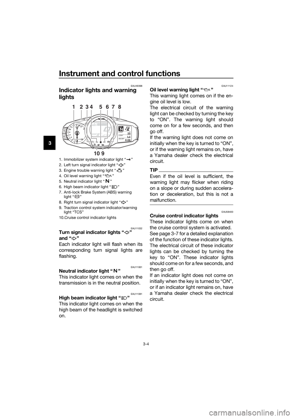
1. Immobilizer system indicator light “ ”
2. Left turn signal indicator light “ ”
3. Engine trouble warning light “ ”
4. Oil level warning light “ ”
5. Neutral indicator light “ ”
6. High beam indicator light “ ”
7. Anti-lock Brake System (ABS) warning light “ ”
8. Right turn signal indicator light “ ”
9. Traction control system indicator/warning light “TCS”
10.Cruise control indicator lights
GEARN25A.TEMP ˚C
LoC.TEMP˚C
0:06TIME TRIP
128374
910
65
ABS
UB88E0E0.book Page 4 Friday, October 16, 2015 11:59 AM
Page 36 of 120

Instrument and control functions
3-22
3
EAU49432
D-mo de ( drive mo de)
D-mode is an electronically controlled
engine performance system with two
mode selections (touring mode “T” and
sports mode “S”).
Push the drive mode switch “MODE”
to switch between modes. (See page
3-23 for an explanation of the drive
mode switch.)
TIP
Before using D-mode, make sure you
understand its operation along with the
operation of the drive mode switch.
Tourin g mo de “T”
The touring mode “T” is suitable for
various riding conditions.
This mode allows the rider to enjoy
smooth drivability from the low-speed
range to the high-speed range.
Sports mo de “S”
This mode offers a sportier engine re-
sponse in the low- to mid-speed range
compared to the touring mode.
EAU1234J
Han dle bar switches
Left
Ri ght
EAU54201Dimmer/Pass switch “ / /PASS”
Set this switch to “ ” for the high
beam and to “ ” for the low beam.
To flash the high beam, push the pass
side “PASS” of the switch while the
headlights are on low beam.
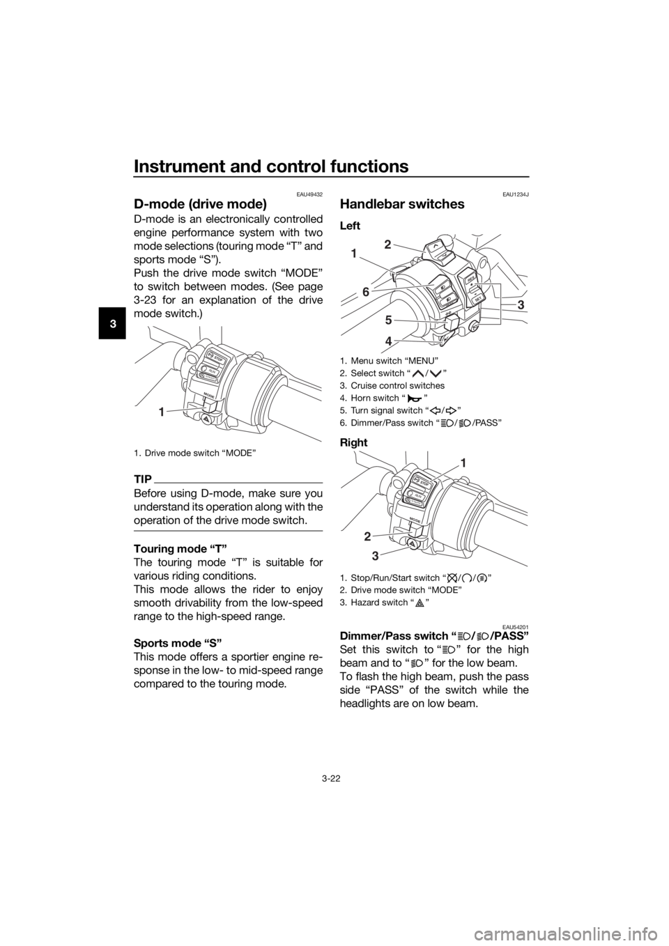
1. Drive mode switch “MODE”
STOP
MODE
RUNSTART
1
1. Menu switch “MENU”
2. Select switch “ / ”
3. Cruise control switches
4. Horn switch “ ”
5. Turn signal switch “ / ”
6. Dimmer/Pass switch “ / /PASS”
1. Stop/Run/Start switch “ / / ”
2. Drive mode switch “MODE”
3. Hazard switch “ ”
RES
SETPA S S
1
6
5
4
2
3
STOP
MODE
RUNSTART
3
2
1
UB88E0E0.book Page 22 Friday, October 16, 2015 11:59 AM
Page 114 of 120

Specifications
8-3
8
Battery:
Model:GT14B-4
Voltage, capacity:
12 V, 12.0 Ah (10 HR)
Bul b watta ge × quantity:
Headlight:
LED
Brake/tail light:
LED
Front turn signal light: LED
Rear turn signal light: LED
Auxiliary light: LED
License plate light:
LED
Meter lighting: LED
Neutral indicator light: LED
High beam indicator light:
LED
Oil level warning light: LED
Turn signal indicator light: LED
Engine trouble warning light:
LED
ABS warning light: LED
Cruise control “SET” indicator light: LED
Cruise control “ON” indicator light:
LED
Immobilizer system indicator light: LED
Traction control system indicator/warning
light: LED
Fuse(s):
Main fuse:
50.0 A
Main fuse 2: 30.0 A
Terminal fuse 1: 3.0 A
Headlight fuse:
7.5 A Brake light fuse:
1.0 A
Signaling system fuse: 7.5 A
Ignition fuse:
20.0 A
Radiator fan motor fuse: 10.0 A × 2
Hazard fuse: 7.5 A
Fuel injection system fuse:
15.0 A
ABS control unit fuse: 7.5 A
ABS motor fuse: 30.0 A
ABS solenoid fuse: 20.0 A
Cruise control fuse:
1.0 A
Backup fuse: 7.5 A
Windshield motor fuse: 20.0 A
Electronic throttle valve fuse:
7.5 A
UB88E0E0.book Page 3 Friday, October 16, 2015 11:59 AM
Page 117 of 120

10-1
10
Index
A
ABS ...................................................... 3-26
ABS warning light ................................... 3-5
Accessory box...................................... 3-36
Air filter element, cleaning .................... 6-17
Auxiliary DC jack .................................. 3-46
B
Battery .................................................. 6-32
Brake and clutch fluid levels,
checking............................................. 6-25
Brake and clutch fluids, changing ........ 6-27
Brake and clutch levers, checking
and lubricating ................................... 6-29
Brake and shift pedals, checking and
lubricating .......................................... 6-28
Brake lever ........................................... 3-25
Brake lever free play, checking ............ 6-23
Brake light switches ............................. 6-24
Brake pedal .......................................... 3-25
C
Cables, checking and lubricating ......... 6-27
Canister ................................................ 6-11
Care ........................................................ 7-1
Catalytic converters ............................. 3-31
Centerstand and sidestand, checking
and lubricating ................................... 6-29
Clutch lever ................................. 3-24, 6-23
Coolant ................................................. 6-15
Cowling vents, opening and closing .... 3-38
Cruise control indicator lights ................ 3-4
Cruise control switches ........................ 3-23
Cruise control system ............................ 3-7
D
Diagnostic connector ............................. 9-2
Dimmer/Pass switch ............................ 3-22
D-mode (drive mode) ........................... 3-22
E
Engine break-in ...................................... 5-5
Engine idling speed, checking ............. 6-18
Engine oil and oil filter cartridge ........... 6-11
Engine serial number.............................. 9-1
Engine trouble warning light................... 3-5
F
Final gear oil ......................................... 6-14
Front and rear brake pads, checking ... 6-24
Front fork, adjusting ............................. 3-40
Front fork, checking ............................. 6-31
Fuel....................................................... 3-29
Fuel consumption, tips for reducing ...... 5-4
Fuel tank cap........................................ 3-28 Fuel tank overflow hose ........................ 3-30
Fuses, replacing.................................... 6-34
H
Handlebar position, adjusting ............... 3-37
Handlebar switches .............................. 3-22
Hazard switch ....................................... 3-23
Headlight beams, adjusting .................. 3-37
High beam indicator light........................ 3-4
Horn switch........................................... 3-23
I
Identification numbers ............................ 9-1
Ignition circuit cut-off system ............... 3-44
Immobilizer system ................................. 3-1
Immobilizer system indicator light .......... 3-6
Indicator lights and warning lights .......... 3-4
M
Main switch/steering lock ....................... 3-2
Maintenance and lubrication, periodic ... 6-4
Maintenance, emission control
system .................................................. 6-3
Matte color, caution ................................ 7-1
Menu switch ......................................... 3-23
Model label ............................................. 9-1
Multi-function meter unit ...................... 3-10
N
Neutral indicator light.............................. 3-4
O
Oil level warning light .............................. 3-4
P
Panels, removing and installing .............. 6-7
Parking .................................................... 5-6
Part locations .......................................... 2-1
R
Rear suspension, lubricating ................ 6-30
Rear view mirrors .................................. 3-39
Rider seat height, adjusting .................. 3-33
S
Safety information................................... 1-1
Seats ..................................................... 3-31
Select switch ........................................ 3-23
Shifting .................................................... 5-3
Shift pedal............................................. 3-24
Shock absorber assembly, adjusting ... 3-42
Sidestand .............................................. 3-43
Spark plugs, checking .......................... 6-10
Specifications ......................................... 8-1
Starting the engine.................................. 5-2
Steering, checking ................................ 6-31
Stop/Run/Start switch .......................... 3-23
Storage ................................................... 7-4
UB88E0E0.book Page 1 Friday, October 16, 2015 11:59 AM