YAMAHA FJR1300A 2018 Owner's Guide
Manufacturer: YAMAHA, Model Year: 2018, Model line: FJR1300A, Model: YAMAHA FJR1300A 2018Pages: 118, PDF Size: 3.5 MB
Page 31 of 118
Instrument and control functions
3-17
3
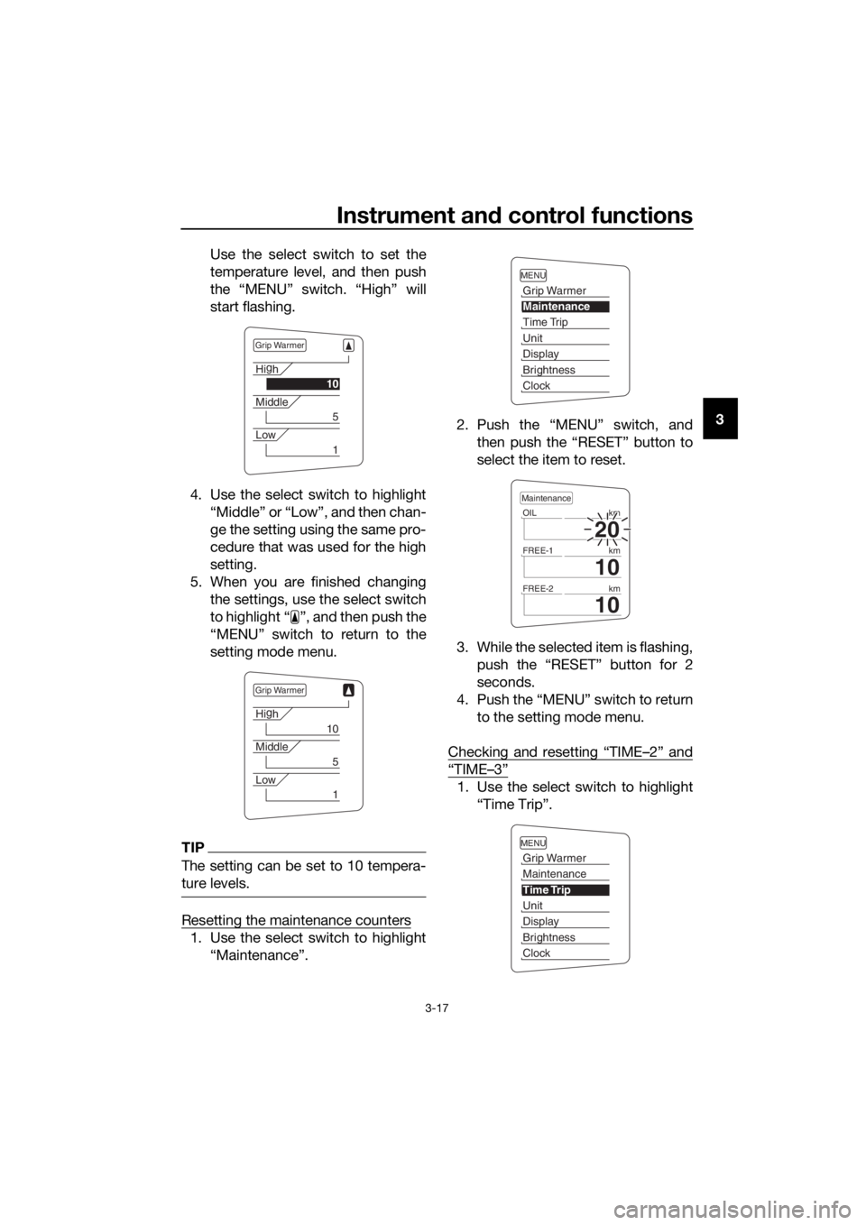
Use the select switch to set the
temperature level, and then push
the “MENU” switch. “High” will
start flashing.
4. Use the select switch to highlight “Middle” or “Low”, and then chan-
ge the setting using the same pro-
cedure that was used for the high
setting.
5. When you are finished changing the settings, use the select switch
to highlight “ ”, and then push the
“MENU” switch to return to the
setting mode menu.
TIP
The setting can be set to 10 tempera-
ture levels.
Resetting the maintenance counters
1. Use the select switch to highlight“Maintenance”. 2. Push the “MENU” switch, and
then push the “RESET” button to
select the item to reset.
3. While the selected item is flashing, push the “RESET” button for 2
seconds.
4. Push the “MENU” switch to return to the setting mode menu.
Checking and resetting “TIME–2” and
“TIME–3”
1. Use the select switch to highlight “Time Trip”.
Grip Warmer
Hig
h
10
Middle
5
Low
1
Grip Warmer
Hi g
h
10
Middle
5
Low
1
MENU
Grip Warmer
Maintenance
Time Trip
Unit
Display
Brightness
Clock
20
OIL km
10
FREE-1km
10
FREE-2km
Maintenance
MENU
Grip Warmer
Maintenance
Time Trip
Unit
Display
Brightness
Clock
UB88E1E0.book Page 17 Monday, July 10, 2017 2:46 PM
Page 32 of 118
Instrument and control functions
3-18
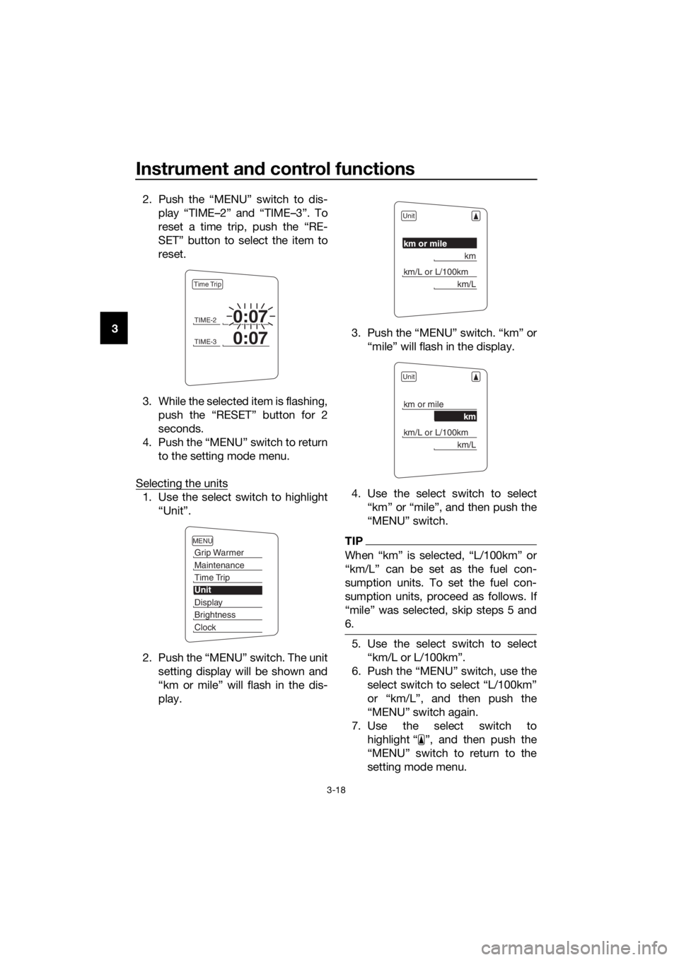
3 2. Push the “MENU” switch to dis-
play “TIME–2” and “TIME–3”. To
reset a time trip, push the “RE-
SET” button to select the item to
reset.
3. While the selected item is flashing, push the “RESET” button for 2
seconds.
4. Push the “MENU” switch to return to the setting mode menu.
Selecting the units
1. Use the select switch to highlight “Unit”.
2. Push the “MENU” switch. The unit setting display will be shown and
“km or mile” will flash in the dis-
play. 3. Push the “MENU” switch. “km” or
“mile” will flash in the display.
4. Use the select switch to select “km” or “mile”, and then push the
“MENU” switch.
TIP
When “km” is selected, “L/100km” or
“km/L” can be set as the fuel con-
sumption units. To set the fuel con-
sumption units, proceed as follows. If
“mile” was selected, skip steps 5 and
6.
5. Use the select switch to select“km/L or L/100km”.
6. Push the “MENU” switch, use the select switch to select “L/100km”
or “km/L”, and then push the
“MENU” switch again.
7. Use the select switch to highlight “ ”, and then push the
“MENU” switch to return to the
setting mode menu.
TIME-20:07
TIME-30:07
Time Trip
MENU
Grip Warmer
Maintenance
Time Trip
Unit
Display
Brightness
Clock
Unit
km or mile
km
km/L or L/100km
km/L
Unit
km or mile
km
km/L or L/100km
km/L
UB88E1E0.book Page 18 Monday, July 10, 2017 2:46 PM
Page 33 of 118
Instrument and control functions
3-19
3
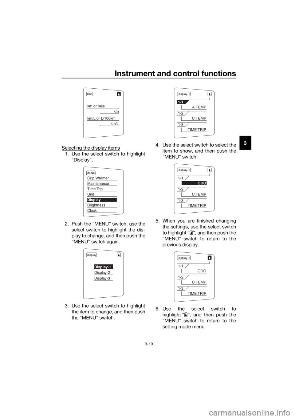
Selecting the display items
1. Use the select switch to highlight
“Display”.
2. Push the “MENU” switch, use the select switch to highlight the dis-
play to change, and then push the
“MENU” switch again.
3. Use the select switch to highlight the item to change, and then push
the “MENU” switch. 4. Use the select switch to select the
item to show, and then push the
“MENU” switch.
5. When you are finished changing the settings, use the select switch
to highlight “ ”, and then push the
“MENU” switch to return to the
previous display.
6. Use the select switch to highlight “ ”, and then push the
“MENU” switch to return to the
setting mode menu.
Unit
km or mile
km
km/L or L/100km
km/L
MENU
Grip Warmer
Maintenance
Time Trip
Unit
Display
Brightness
Clock
Display
Display-1
Display-2
Display-3
Display-1
1-1
A.TEMP
1-2
C.TEMP
1-3
TIME TRIP
Display-1
1-1
ODO
1-2
C.TEMP
1-3
TIME TRIP
Display-1
1-1
ODO
1-2
C.TEMP
1-3
TIME TRIP
UB88E1E0.book Page 19 Monday, July 10, 2017 2:46 PM
Page 34 of 118
Instrument and control functions
3-20
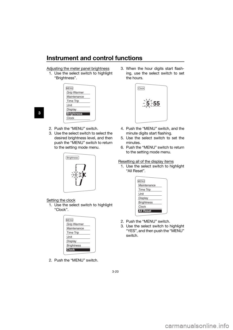
3 Adjusting the meter panel brightness
1. Use the select switch to highlight
“Brightness”.
2. Push the “MENU” switch.
3. Use the select switch to select the desired brightness level, and then
push the “MENU” switch to return
to the setting mode menu.
Setting the clock
1. Use the select switch to highlight “Clock”.
2. Push the “MENU” switch. 3. When the hour digits start flash-
ing, use the select switch to set
the hours.
4. Push the “MENU” switch, and the minute digits start flashing.
5. Use the select switch to set the minutes.
6. Push the “MENU” switch to return to the setting mode menu.
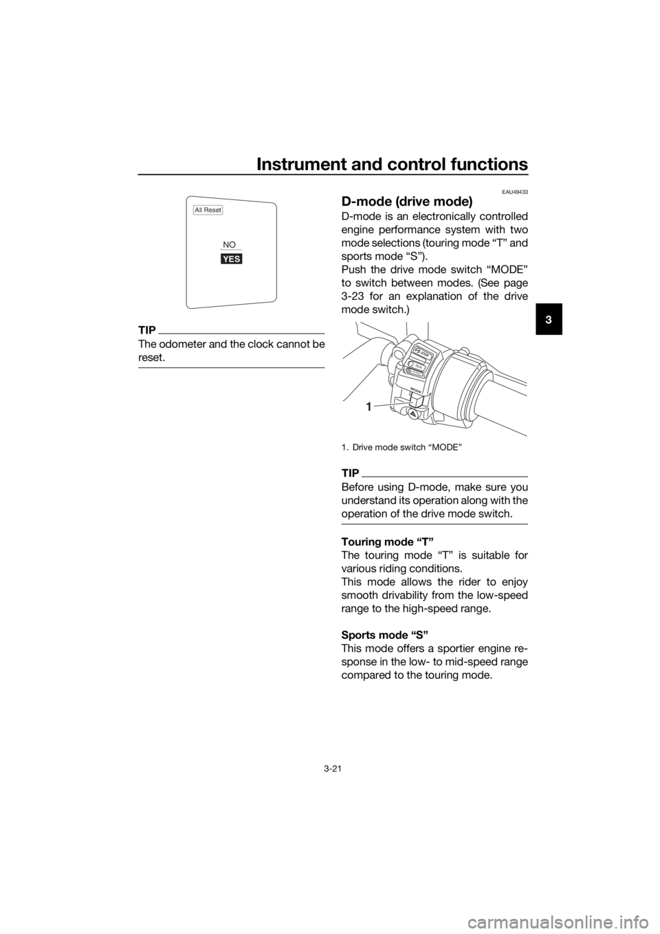
Resetting all of the display items
1. Use the select switch to highlight “All Reset”.
2. Push the “MENU” switch.
3. Use the select switch to highlight “YES”, and then push the “MENU”
switch.
MENU
Grip Warmer
Maintenance
Time Trip
Unit
Display
Brightness
Clock
Brightness
MENU
Grip Warmer
Maintenance
Time Trip
Unit
Display
Brightness
Clock
Clock
555
MENU
Maintenance
Time Trip
Unit
Display
Brightness
Clock
All Reset
UB88E1E0.book Page 20 Monday, July 10, 2017 2:46 PM
Page 35 of 118
Instrument and control functions
3-21
3TIP
The odometer and the clock cannot be
reset.
EAU49433
D-mo de ( drive mo de)
D-mode is an electronically controlled
engine performance system with two
mode selections (touring mode “T” and
sports mode “S”).
Push the drive mode switch “MODE”
to switch between modes. (See page
3-23 for an explanation of the drive
mode switch.)
TIP
Before using D-mode, make sure you
understand its operation along with the
operation of the drive mode switch.
Tourin g mo de “T”
The touring mode “T” is suitable for
various riding conditions.
This mode allows the rider to enjoy
smooth drivability from the low-speed
range to the high-speed range.
Sports mod e “S”
This mode offers a sportier engine re-
sponse in the low- to mid-speed range
compared to the touring mode.
All Reset
YES
NO
1. Drive mode switch “MODE”
STOP
M ODE
RUNSTART
1
UB88E1E0.book Page 21 Monday, July 10, 2017 2:46 PM
Page 36 of 118
Instrument and control functions
3-22
3
EAU1234M
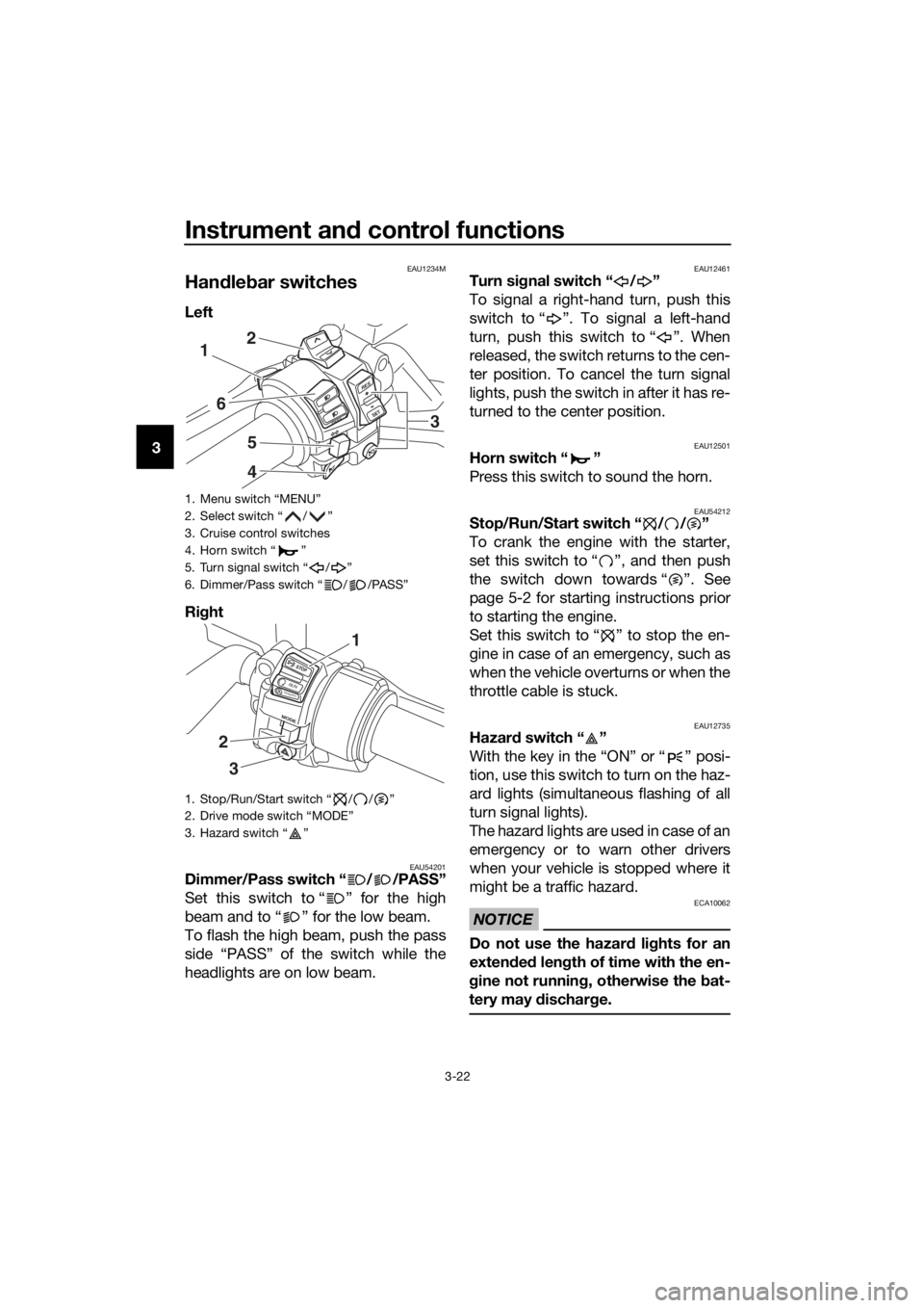
Han dle bar switches
Left
Ri ght
EAU54201Dimmer/Pass switch “ / /PASS”
Set this switch to “ ” for the high
beam and to “ ” for the low beam.
To flash the high beam, push the pass
side “PASS” of the switch while the
headlights are on low beam.
EAU12461Turn si gnal switch “ / ”
To signal a right-hand turn, push this
switch to “ ”. To signal a left-hand
turn, push this switch to “ ”. When
released, the switch returns to the cen-
ter position. To cancel the turn signal
lights, push the switch in after it has re-
turned to the center position.
EAU12501Horn switch “ ”
Press this switch to sound the horn.
EAU54212Stop/Run/Start switch “ / / ”
To crank the engine with the starter,
set this switch to “ ”, and then push
the switch down towards “ ”. See
page 5-2 for starting instructions prior
to starting the engine.
Set this switch to “ ” to stop the en-
gine in case of an emergency, such as
when the vehicle overturns or when the
throttle cable is stuck.
EAU12735Hazar d switch “ ”
With the key in the “ON” or “ ” posi-
tion, use this switch to turn on the haz-
ard lights (simultaneous flashing of all
turn signal lights).
The hazard lights are used in case of an
emergency or to warn other drivers
when your vehicle is stopped where it
might be a traffic hazard.
NOTICE
ECA10062
Do not use the hazar d lig hts for an
exten ded len gth of time with the en-
g ine not runnin g, otherwise the bat-
tery may dischar ge.
1. Menu switch “MENU”
2. Select switch “ / ”
3. Cruise control switches
4. Horn switch “ ”
5. Turn signal switch “ / ”
6. Dimmer/Pass switch “ / /PASS”
1. Stop/Run/Start switch “ / / ”
2. Drive mode switch “MODE”
3. Hazard switch “ ”
R ES
SETPA S S
1
6
5
4
2
3
STOP
MODE
RUNSTART
3
2
1
UB88E1E0.book Page 22 Monday, July 10, 2017 2:46 PM
Page 37 of 118
Instrument and control functions
3-23
3
EAU12781Cruise control switches
See page 3-6 for an explanation of the
cruise control system.
EAU54232Menu switch “MENU”
This switch is used to make setting
changes within the multi-function me-
ter unit. (See page 3-9.)
EAU54222Select switch “ / ”
This switch is used to make setting
changes within the multi-function me-
ter unit. (See page 3-9.)
EAU54691Drive mo de switch “MODE”
WARNING
EWA15341
Do not chan ge the D-mo de while the
vehicle is movin g.
Using this switch changes the drive
mode to touring mode “T” or sports
mode “S”.
The throttle grip must be completely
closed in order to change the drive mo-
de.
The selected mode is shown on the
drive mode display. (See page 3-11.)
The drive mode cannot be changed
while the cruise control system is oper-
ating.
EAU12832
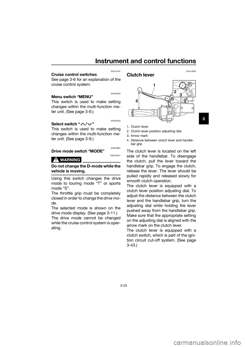
Clutch lever
The clutch lever is located on the left
side of the handlebar. To disengage
the clutch, pull the lever toward the
handlebar grip. To engage the clutch,
release the lever. The lever should be
pulled rapidly and released slowly for
smooth clutch operation.
The clutch lever is equipped with a
clutch lever position adjusting dial. To
adjust the distance between the clutch
lever and the handlebar grip, turn the
adjusting dial while holding the lever
pushed away from the handlebar grip.
Make sure that the appropriate setting
on the adjusting dial is aligned with the
arrow mark on the clutch lever.
The clutch lever is equipped with a
clutch switch, which is part of the igni-
tion circuit cut-off system. (See page
3-43.)
1. Clutch lever
2. Clutch lever position adjusting dial
3. Arrow mark
4. Distance between clutch lever and handle-
bar grip
15432
4 1
2
3
UB88E1E0.book Page 23 Monday, July 10, 2017 2:46 PM
Page 38 of 118
Instrument and control functions
3-24
3
EAU12872
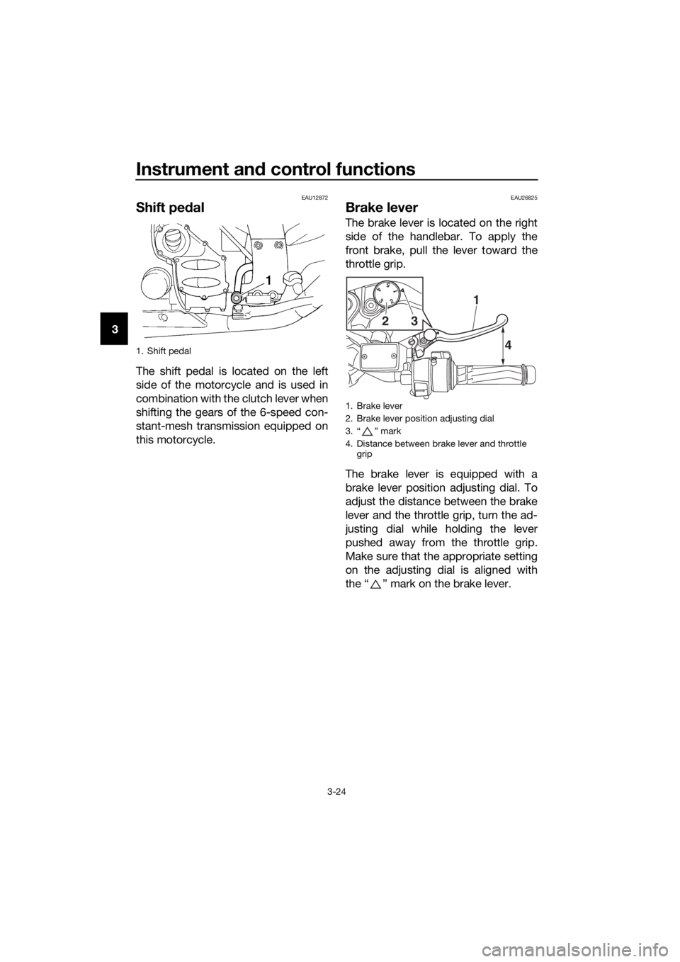
Shift pe dal
The shift pedal is located on the left
side of the motorcycle and is used in
combination with the clutch lever when
shifting the gears of the 6-speed con-
stant-mesh transmission equipped on
this motorcycle.
EAU26825
Brake lever
The brake lever is located on the right
side of the handlebar. To apply the
front brake, pull the lever toward the
throttle grip.
The brake lever is equipped with a
brake lever position adjusting dial. To
adjust the distance between the brake
lever and the throttle grip, turn the ad-
justing dial while holding the lever
pushed away from the throttle grip.
Make sure that the appropriate setting
on the adjusting dial is aligned with
the “ ” mark on the brake lever.
1. Shift pedal
1. Brake lever
2. Brake lever position adjusting dial
3. “ ” mark
4. Distance between brake lever and throttle
grip
154
32
4
1
32
UB88E1E0.book Page 24 Monday, July 10, 2017 2:46 PM
Page 39 of 118
Instrument and control functions
3-25
3
EAU39542
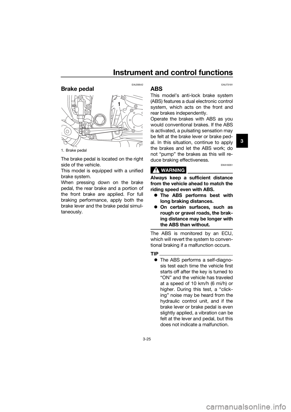
Brake ped al
The brake pedal is located on the right
side of the vehicle.
This model is equipped with a unified
brake system.
When pressing down on the brake
pedal, the rear brake and a portion of
the front brake are applied. For full
braking performance, apply both the
brake lever and the brake pedal simul-
taneously.
EAU73181
ABS
This model’s anti-lock brake system
(ABS) features a dual electronic control
system, which acts on the front and
rear brakes independently.
Operate the brakes with ABS as you
would conventional brakes. If the ABS
is activated, a pulsating sensation may
be felt at the brake lever or brake ped-
al. In this situation, continue to apply
the brakes and let the ABS work; do
not “pump” the brakes as this will re-
duce braking effectiveness.
WARNING
EWA16051
Always keep a sufficient distance
from the vehicle ahea d to match the
ri din g speed even with ABS.
The ABS performs best with
lon g b rakin g d istances.
On certain surfaces, such as
rou gh or g ravel roa ds, the b rak-
in g d istance may be lon ger with
the ABS than without.
The ABS is monitored by an ECU,
which will revert the system to conven-
tional braking if a malfunction occurs.
TIP
The ABS performs a self-diagno-
sis test each time the vehicle first
starts off after the key is turned to
“ON” and the vehicle has traveled
at a speed of 10 km/h (6 mi/h) or
higher. During this test, a “click-
ing” noise may be heard from the
hydraulic control unit, and if the
brake lever or brake pedal is even
slightly applied, a vibration can be
felt at the lever and pedal, but this
does not indicate a malfunction.
1. Brake pedal
1
UB88E1E0.book Page 25 Monday, July 10, 2017 2:46 PM
Page 40 of 118
Instrument and control functions
3-26
3
This ABS has a test mode which
allows the owner to experience
the pulsation at the brake lever or
brake pedal when the ABS is op-
erating. However, special tools are
required, so please consult your
Yamaha dealer.
NOTICE
ECA16831
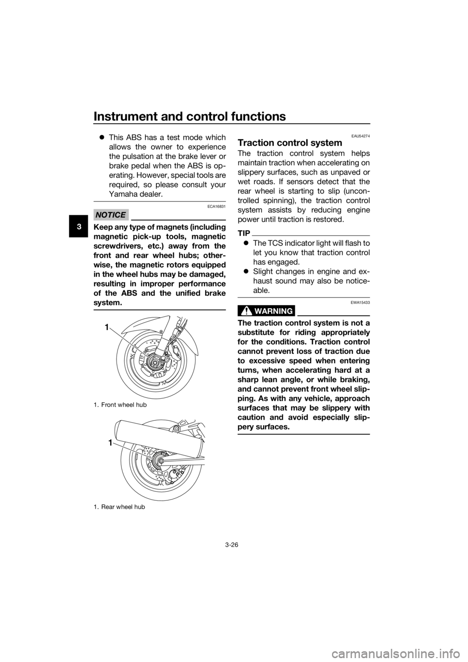
Keep any type of mag nets (including
ma gnetic pick-up tools, mag netic
screw drivers, etc.) away from the
front an d rear wheel hu bs; other-
wise, the ma gnetic rotors equippe d
in the wheel hu bs may be damag ed ,
resultin g in improper performance
of the ABS an d the unifie d b rake
system.
EAU54274
Traction control system
The traction control system helps
maintain traction when accelerating on
slippery surfaces, such as unpaved or
wet roads. If sensors detect that the
rear wheel is starting to slip (uncon-
trolled spinning), the traction control
system assists by reducing engine
power until traction is restored.
TIP
The TCS indicator light will flash to
let you know that traction control
has engaged.
Slight changes in engine and ex-
haust sound may also be notice-
able.
WARNING
EWA15433
The traction control system is not a
substitute for ri din g appropriately
for the con ditions. Traction control
cannot prevent loss of traction due
to excessive speed when entering
turns, when acceleratin g har d at a
sharp lean an gle, or while b raking,
an d cannot prevent front wheel slip-
pin g. As with any vehicle, approach
surfaces that may b e slippery with
caution an d avoi d especially slip-
pery surfaces.
1. Front wheel hub
1. Rear wheel hub
1
1
UB88E1E0.book Page 26 Monday, July 10, 2017 2:46 PM