warning YAMAHA FJR1300AE 2014 Owner's Manual
[x] Cancel search | Manufacturer: YAMAHA, Model Year: 2014, Model line: FJR1300AE, Model: YAMAHA FJR1300AE 2014Pages: 120, PDF Size: 3.33 MB
Page 52 of 120

INSTRUMENT AND CONTROL FUNCTIONS
3-37
3When storing documents or other
items in a storage compartment, be
sure to wrap them in a plastic bag so
that they will not get wet. When wash-
ing the vehicle, be careful not to let any
water enter a storage compartment.
WARNING
EWA14421
Do not exceed the load limit of 1
k g (2 l b) for stora ge compart-
ment A.
Do not exceed the load limit of 3
k g (7 l b) for stora ge compart-
ment B.
Do not exceed the maximum
loa d of 212 k g (467 l b) for the ve-
hicle.
EAU39481
Accessory boxThe accessory box is located beside
the meter panel.
To open the accessory box
1. Insert the key into the main switch, and then turn it to “ON”.
2. Push the accessory box button, and then open the accessory box
lid.
3. Turn the key to “OFF” to preserve the battery.
To close the accessory box
1. Fold the accessory box lid down. 2. Remove the key.
NOTICE
ECA11801
Do not place heat-sensitive items in
the accessory
box. The accessory
b ox gets extremely hot especially
when the en gine is runnin g or is hot.
WARNING
EWA11422
Do not exceed the load limit of
0.3 k g (0.66 l b) for the accessory
b ox.
Do not exceed the maximum
loa d of 212 k g (467 l b) for the ve-
hicle.
1. Storage compartment B1
1. Accessory box lid
2. Accessory box
3. Accessory box button
1
2
3
U2PDE0E0.book Page 37 Monday, July 15, 2013 9:43 AM
Page 55 of 120
INSTRUMENT AND CONTROL FUNCTIONS
3-40
3
EAU39672
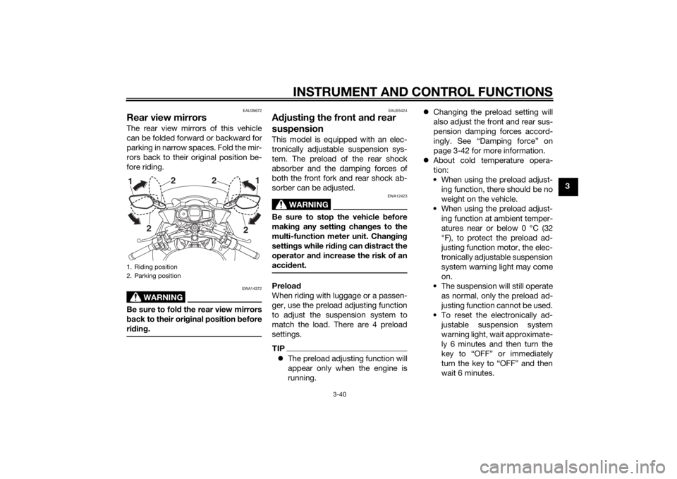
Rear view mirrorsThe rear view mirrors of this vehicle
can be folded forward or backward for
parking in narrow spaces. Fold the mir-
rors back to their original position be-
fore riding.
WARNING
EWA14372
Be sure to fold the rear view mirrors
b ack to their ori ginal position before
ri din g.
EAU55424
A djustin g the front an d rear
suspensionThis model is equipped with an elec-
tronically adjustable suspension sys-
tem. The preload of the rear shock
absorber and the damping forces of
both the front fork and rear shock ab-
sorber can be adjusted.
WARNING
EWA12423
Be sure to stop the vehicle before
makin g any settin g chan ges to the
multi-function meter unit. Chan gin g
settin gs while ri din g can distract the
operator an d increase the risk of an
acci dent.Preloa d
When riding with luggage or a passen-
ger, use the preload adjusting function
to adjust the suspension system to
match the load. There are 4 preload
settings.TIP The preload adjusting function will
appear only when the engine is
running.
Changing the preload setting will
also adjust the front and rear sus-
pension damping forces accord-
ingly. See “Damping force” on
page 3-42 for more information.
About cold temperature opera-
tion:
• When using the preload adjust- ing function, there should be no
weight on the vehicle.
• When using the preload adjust- ing function at ambient temper-
atures near or below 0 °C (32
°F), to protect the preload ad-
justing function motor, the elec-
tronically adjustable suspension
system warning light may come
on.
• The suspension will still operate as normal, only the preload ad-
justing function cannot be used.
• To reset the electronically ad- justable suspension system
warning light, wait approximate-
ly 6 minutes and then turn the
key to “OFF” or immediately
turn the key to “OFF” and then
wait 6 minutes.
1. Riding position
2. Parking position
2
2
1
2 2
1
U2PDE0E0.book Page 40 Monday, July 15, 2013 9:43 AM
Page 56 of 120

INSTRUMENT AND CONTROL FUNCTIONS
3-41
3• If the electronically adjustable
suspension system warning
light remains on, have a
Yamaha dealer check the sus- pension system.
To adjust the preload1. Turn the key to “ON”, start the en- gine, and then shift the transmis-
sion into neutral.
2. Push the menu switch “MENU” to switch the function display to the
preload adjusting function. 3. Use the select switch to select the
desired preload setting pictogram.
Select the suitable setting from
the following 4 pictograms ac-
cording to your load condition. While the preload is being adjust-
ed, the information display will
show a group of dots moving in a
circle. Once the selected picto-
gram returns, the preload adjust-
ment is complete.1. Function display
2. Preload adjusting function
3. Preload setting pictogram
GEARN
132
1. Menu switch “MENU”
2. Select switch “ / ”
1
2
1. Solo riding
2. Solo riding and luggage
3. Passenger riding
4. Passenger riding and luggage1
2
3
4
GEARN
GEARN
U2PDE0E0.book Page 41 Monday, July 15, 2013 9:43 AM
Page 59 of 120
INSTRUMENT AND CONTROL FUNCTIONS
3-44
3
WARNING
EWA16421
The rear shock absorber assem bly
contains hi ghly pressurize d nitro gen
g as. Rea d an d un derstan d the fol-
lowin g information before han dlin g
the shock ab sorber assem bly.
Do not tamper with or attempt
to open the cylin der assem bly.
Do not su bject the shock a b-
sor ber assem bly to an open
flame or other hi gh heat source.
This may cause the unit to ex-
plod e due to excessive gas
pressure.
Do not deform or damag e the
cylin der in any way. Cylin der
d amag e will result in poor
d ampin g performance.
Do not dispose of a d amaged or
worn-out shock ab sorber as-
se
m bly yourself. Take the shock
a b sor ber assem bly to a Yamaha
d ealer for any service.
EAU15306
Si destan dThe sidestand is located on the left
side of the frame. Raise the sidestand
or lower it with your foot while holding
the vehicle upright.TIPThe built-in sidestand switch is part of
the ignition circuit cut-off system,
which cuts the ignition in certain situa-
tions. (See the following section for an
explanation of the ignition circuit cut-
off system.)
WARNING
EWA10242
The vehicle must not be ri dden with
the si destan d d own, or if the si de-
stan d cannot b e properly move d up
(or does not stay up), otherwise the
si destan d coul d contact the g round
an d d istract the operator, resultin g
in a possib le loss of control.
Yamaha’s ig nition circuit cut-off
system has been desi gne d to assist
the operator in fulfillin g the respon-
si bility of raisin g the sid estand b e-
fore startin g off. Therefore, check
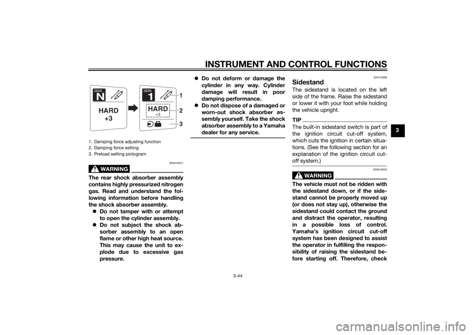
1. Damping force adjusting function
2. Damping force setting
3. Preload setting pictogram
GEARNHARD
+3
GEAR1HARD
+3
123
U2PDE0E0.book Page 44 Monday, July 15, 2013 9:43 AM
Page 62 of 120

INSTRUMENT AND CONTROL FUNCTIONS
3-47
3
EAU39656
Auxiliary DC jack
WARNING
EWA14361
To prevent electrical shock or short-
circuiting, make sure that the cap is
installe d when the auxiliary DC jack
is not bein g use d.NOTICE
ECA15432
The accessory connecte d to the
auxiliary DC jack shoul d not b e used
with the en gine turne d off, an d the
loa d must never exceed 30 W (2.5 A),
otherwise the fuse may blow or the
b attery may d ischarge.This vehicle is equipped with an auxil-
iary DC jack in the accessory box.
A 12-V accessory connected to the
auxiliary jack can be used when the
key is in the “ON” position and should
only be used when the engine is run-
ning.
To use the auxiliary DC jack
1. Open the accessory box lid. (See page 3-37.)
2. Turn the key to “OFF”. 3. Remove the auxiliary DC jack cap.
4. Turn the accessory off.
5. Insert the accessory plug into the
auxiliary DC jack.
6. Turn the key to “ON”, and then start the engine. (See page 5-1.)
7. Turn the accessory on.
1. Auxiliary DC jack cap
1. Auxiliary DC jack
11
U2PDE0E0.book Page 47 Monday, July 15, 2013 9:43 AM
Page 63 of 120

FOR YOUR SAFETY – PRE-OPERATION CHECKS
4-1
4
EAU15598
Inspect your vehicle each time you use it to make sure the vehicle is in safe operating condition. Always follow the inspection
and maintenance procedures and schedules described in the Owner’s Manual.
WARNING
EWA11152
Failure to inspect or maintain the vehicle properly increases the possibility of an accident or equipment d amage.
Do not operate the vehicle if you fin d any pro blem. If a pro blem cannot b e corrected b y the proce dures provi ded in
this manual, have the vehicle inspecte d b y a Yamaha dealer.Before using this vehicle, check the following points:
ITEM CHECKS PAGE
Fuel • Check fuel level in fuel tank.
• Refuel if necessary.
• Check fuel line for leakage.
• Check fuel tank breather/overflow hose for obstructions, cracks or damage, and
check hose connection. 3-31, 3-32
En gine oil • Check oil level in engine.
• If necessary, add recommended oil to specified level.
• Check vehicle for oil leakage. 6-12
Final gear oil • Check vehicle for oil leakage. 6-14
Coolant • Check coolant level in reservoir.
• If necessary, add recommended coolant to specified level.
• Check cooling system for leakage. 6-16
Front brake • Check operation.
• If soft or spongy, have Yamaha dealer bleed hydraulic system.
• Check brake pads for wear.
• Replace if necessary.
• Check fluid level in reservoir.
• If necessary, add specified brake fluid to specified level.
• Check hydraulic system for leakage. 6-24, 6-24
U2PDE0E0.book Page 1 Monday, July 15, 2013 9:43 AM
Page 66 of 120
OPERATION AND IMPORTANT RIDING POINTS
5-1
5
EAU15952
Read the Owner’s Manual carefully to
become familiar with all controls. If
there is a control or function you do not
understand, ask your Yamaha dealer.
WARNING
EWA10272
Failure to familiarize yourself with
the controls can lead to loss of con-
trol, which coul d cause an acci dent
or injury.
EAU47151
TIPThis model is equipped with: a lean angle sensor to stop the en-
gine in case of a turnover. In this
case, the multi-function meter unit
indicates error code 30, but this is
not a malfunction. Turn the key to
“OFF” and then to “ON” to clear
the error code. Failing to do so will
prevent the engine from starting
even though the engine will crank
when pushing the start switch.
an engine auto-stop system. The
engine stops automatically if left
idling for 20 minutes. In this case,
the multi-function meter unit indi-
cates error code 70, but this is not
a malfunction. Push the start
switch to clear the error code and
to restart the engine.
EAU58240
Startin g the en gineIn order for the ignition circuit cut-off
system to enable starting, one of the
following conditions must be met:
The transmission is in the neutral
position.
The transmission is in gear with
the clutch lever pulled and the
sidestand up.
See page 3-45 for more informa-
tion.
1. Turn the key to “ON” and make sure that the start/engine stop
switch is set to “ ”.
The following warning lights and
indicator lights should come on for
a few seconds, then go off. Oil level warning light
Engine trouble warning light
Traction control system indi-
cator/warning light
Cruise control indicator lights
Electronically adjustable sus-
pension system warning light
Immobilizer system indicator
light
U2PDE0E0.book Page 1 Monday, July 15, 2013 9:43 AM
Page 67 of 120
OPERATION AND IMPORTANT RIDING POINTS
5-2
5
NOTICE
ECA11834
If a warning or in dicator li ght does
not come on initially when the key is
turne d to “ON”, or if a warnin g or in-
d icator li ght remains on, see pa ge
3-4 for the correspon din g warnin g
an d in dicator li ght circuit check.
The ABS warning light should
come on when the key is turned to
“ON”, and then go off after travel-
ing at a speed of 10 km/h (6 mi/h)
or higher.
NOTICE
ECA17682
If the ABS warnin g li ght does not
come on an d then go off as ex-
plaine d a bove, see pa ge 3-4 for the
warnin g li ght circuit check.2. Shift the transmission into the
neutral position. The neutral indi-
cator light should come on. If not,
ask a Yamaha dealer to check the
electrical circuit.
3. Start the engine by pushing the “ ” side of the start/engine
stop switch. If the engine fails to start, release
the start/engine stop switch, wait
a few seconds, and then try again.
Each starting attempt should be
as short as possible to preserve
the battery. Do not crank the en-
gine more than 10 seconds on any
one attempt.
NOTICE
ECA11043
For maximum en
gine life, never ac-
celerate har d when the en gine is
col d!
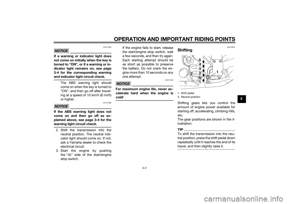
EAU16672
Shiftin gShifting gears lets you control the
amount of engine power available for
starting off, accelerating, climbing hills,
etc.
The gear positions are shown in the il-
lustration.TIPTo shift the transmission into the neu-
tral position, press the shift pedal down
repeatedly until it reaches the end of its
travel, and then slightly raise it.1. Shift pedal
2. Neutral position
U2PDE0E0.book Page 2 Monday, July 15, 2013 9:43 AM
Page 69 of 120

OPERATION AND IMPORTANT RIDING POINTS
5-4
5
1000–1600 km (600–1000 mi)
Avoid prolonged operation above 5400
r/min.
1600 km (1000 mi) an
d b eyon d
The vehicle can now be operated nor-
mally.
NOTICE
ECA10311
Keep the en gine speed out of
the tachometer re d zone.
If any en gine trou ble shoul d oc-
cur durin g the en gine break-in
period , imme diately have a
Yamaha dealer check the vehi-
cle.
EAU17214
Parkin gWhen parking, stop the engine, and
then remove the key from the main
switch.
WARNING
EWA10312
Since the en gine an d exhaust
system can b ecome very hot,
park in a place where ped estri-
ans or chil dren are not likely to
touch them an d b e burne d.
Do not park on a slope or on soft
groun d, otherwise the vehicle
may overturn, increasin g the
risk of a fuel leak an d fire.
Do not park near grass or other
flamma ble materials which
mi ght catch fire.
U2PDE0E0.book Page 4 Monday, July 15, 2013 9:43 AM
Page 70 of 120

PERIODIC MAINTENANCE AND ADJUSTMENT
6-1
6
EAU17245
Periodic inspection, adjustment, and
lubrication will keep your vehicle in the
safest and most efficient condition
possible. Safety is an obligation of the
vehicle owner/operator. The most im-
portant points of vehicle inspection,
adjustment, and lubrication are ex-
plained on the following pages.
The intervals given in the periodic
maintenance charts should be simply
considered as a general guide under
normal riding conditions. However, de-
pending on the weather, terrain, geo-
graphical location, and individual use,
the maintenance intervals may need to
be shortened.
WARNING
EWA10322
Failure to properly maintain the vehi-
cle or performing maintenance ac-
tivities incorrectly may increase
your risk of injury or death durin g
service or while usin g the vehicle. If
you are not familiar with vehicle ser-
vice, have a Yamaha d ealer perform
service.
WARNING
EWA15123
Turn off the en gine when performin g
maintenance unless otherwise
specified .
A runnin g en gine has movin g
parts that can catch on body
parts or clothin g an d electrical
parts that can cause shocks or
fires.
Runnin g the en gine while ser-
vicin g can lead to eye injury,
b urns, fire, or car bon monoxi de
poisonin g – possi bly lea din g to
d eath. See pag e 1-3 for more in-
formation a bout car bon monox-
i d e.
WARNING
EWA15461
Brake discs, calipers, drums, and
linin gs can b ecome very hot d uring
use. To avoi d possi ble burns, let
b rake components cool before
touchin g them.
EAU17303
Emission controls not only function to
ensure cleaner air, but are also vital to
proper engine operation and maximum
performance. In the following periodic
maintenance charts, the services relat-
ed to emissions control are grouped
separately. These services require
specialized data, knowledge, and
equipment. Maintenance, replace-
ment, or repair of the emission control
devices and systems may be per-
formed by any repair establishment or
individual that is certified (if applicable).
Yamaha dealers are trained and equipped to perform these particular
services.
U2PDE0E0.book Page 1 Monday, July 15, 2013 9:43 AM