odometer YAMAHA FJR1300AE 2015 Owners Manual
[x] Cancel search | Manufacturer: YAMAHA, Model Year: 2015, Model line: FJR1300AE, Model: YAMAHA FJR1300AE 2015Pages: 122, PDF Size: 3.4 MB
Page 26 of 122

INSTRUMENT AND CONTROL FUNCTIONS
3-11
3
a transmission gear display
a drive mode display (which
shows the selected drive mode)
a function display (which shows
the selected function)
an information display (which
shows various information, such
as the odometer reading)
a setting mode display (which al-
lows you to set, select, or reset the
items shown in the information
display)
a self-diagnosis device
TIPBe sure to turn the key to “ON” be-
fore pushing the select
switch “ / ”, menu switch
“MENU”, “RESET” button and
“TCS” button.
For the UK only: To switch the me-
ter displays between kilometers
and miles, see page 3-17.Speed ometer
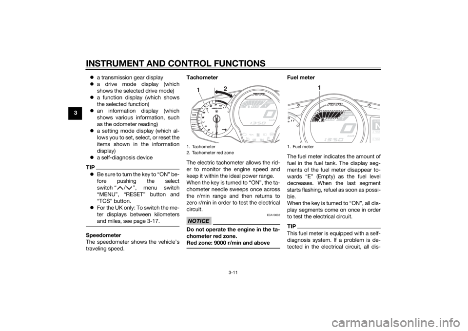
The speedometer shows the vehicle’s
traveling speed. Tachometer
The electric tachometer allows the rid-
er to monitor the engine speed and
keep it within the ideal power range.
When the key is turned to “ON”, the ta-
chometer needle sweeps once across
the r/min range and then returns to
zero r/min in order to test the electrical
circuit.
NOTICE
ECA10032
Do not operate the en
gine in the ta-
chometer red zone.
Re d zone: 9000 r/min an d a bove
Fuel meter
The fuel meter indicates the amount of
fuel in the fuel tank. The display seg-
ments of the fuel meter disappear to-
wards “E” (Empty) as the fuel level
decreases. When the last segment
starts flashing, refuel as soon as possi-
ble.
When the key is turned to “ON”, all dis-
play segments come on once in order
to test the electrical circuit.TIPThis fuel meter is equipped with a self-
diagnosis system. If a problem is de-
tected in the electrical circuit, all dis-
1. Tachometer
2. Tachometer red zone
1 2
1. Fuel meter
GEARNA.TEM
P
C.TEM
P
1
U2PDE1E0.book Page 11 Thursday, July 10, 2014 5:19 PM
Page 29 of 122

INSTRUMENT AND CONTROL FUNCTIONS
3-14
3
Selectin
g the information display
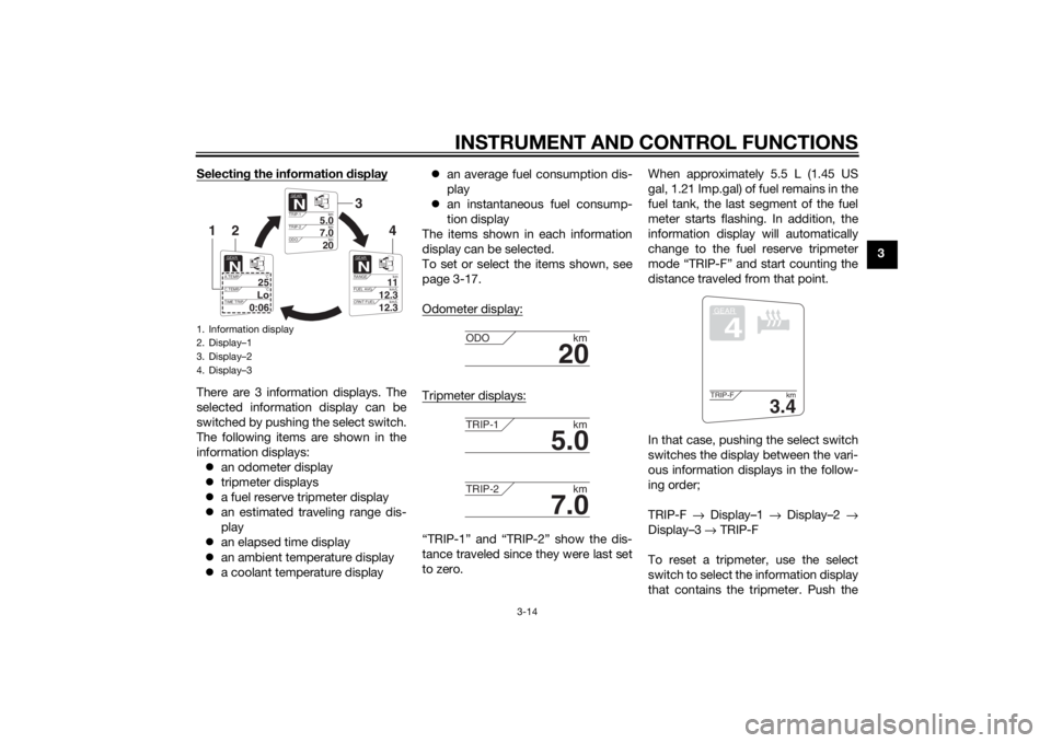
There are 3 information displays. The
selected information display can be
switched by pushing the select switch.
The following items are shown in the
information displays:
an odometer display
tripmeter displays
a fuel reserve tripmeter display
an estimated traveling range dis-
play
an elapsed time display
an ambient temperature display
a coolant temperature display
an average fuel consumption dis-
play
an instantaneous fuel consump-
tion display
The items shown in each information
display can be selected.
To set or select the items shown, see
page 3-17.
Odometer display:
Tripmeter displays:“TRIP-1” and “TRIP-2” show the dis-
tance traveled since they were last set
to zero. When approximately 5.5 L (1.45 US
gal, 1.21 Imp.gal) of fuel remains in the
fuel tank, the last segment of the fuel
meter starts flashing. In addition, the
information display will automatically
change to the fuel reserve tripmeter
mode “TRIP-F” and start counting the
distance traveled from that point.
In that case, pushing the select switch
switches the display between the vari-
ous information displays in the follow-
ing order;
TRIP-F
→ Display–1 → Display–2 →
Display–3 → TRIP-F
To reset a tripmeter, use the select
switch to select the information display
that contains the tripmeter. Push the
1. Information display
2. Display–1
3. Display–2
4. Display–3
GEARN
5.0
TRIP-1 km
7.0
TRIP-2km
km
20
ODO
GEARN
11
RANGEkm
12.3
FUEL AVG km/L
km/L
12.3
CRNT FUEL
GEARN
25
A.TEMP ˚C
Lo
C.TEMP ˚C
0:06
TIME TRIP
3
4
2
1
20
ODOkm
5.0
TRIP-1km
7.0
TRIP-2km
GEAR4
3.4
TRIP-F km
U2PDE1E0.book Page 14 Thursday, July 10, 2014 5:19 PM
Page 33 of 122

INSTRUMENT AND CONTROL FUNCTIONS
3-18
3
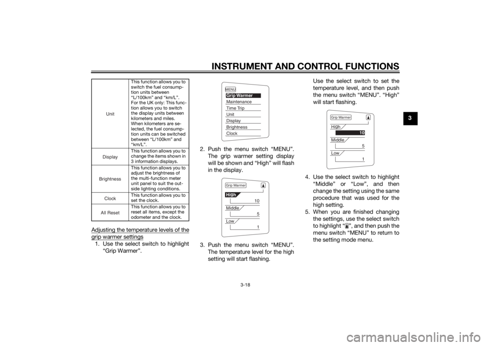
Adjusting the temperature levels of the
grip warmer settings1. Use the select switch to highlight “Grip Warmer”. 2. Push the menu switch “MENU”.
The grip warmer setting display
will be shown and “High” will flash
in the display.
3. Push the menu switch “MENU”. The temperature level for the high
setting will start flashing. Use the select switch to set the
temperature level, and then push
the menu switch “MENU”. “High”
will start flashing.
4. Use the select switch to highlight “Middle” or “Low”, and then
change the setting using the same
procedure that was used for the
high setting.
5. When you are finished changing the settings, use the select switch
to highlight “ ”, and then push the
menu switch “MENU” to return to
the setting mode menu.
This function allows you to
switch the fuel consump-
tion units between
“L/100km” and “km/L”.
For the UK only: This func-
tion allows you to switch
the display units between
kilometers and miles.
When kilometers are se-
lected, the fuel consump-
tion units can be switched
between “L/100km” and
“km/L”.
This function allows you to
change the items shown in
3 information displays.
This function allows you to
adjust the brightness of
the multi-function meter
unit panel to suit the out-
side lighting conditions.
This function allows you to
set the clock.
This function allows you to
reset all items, except the
odometer and the clock.
UnitDisplayBrightnessCloc
k
All Reset
MENUGrip WarmerMaintenanceTime TripUnitDisplayBrightnessClockGrip WarmerHig
h
10
Middle
5
Low
1
Grip WarmerHi g
h
10
Middle
5
Low
1
U2PDE1E0.book Page 18 Thursday, July 10, 2014 5:19 PM
Page 38 of 122

INSTRUMENT AND CONTROL FUNCTIONS
3-23
3
TIPThe odometer and the clock cannot be
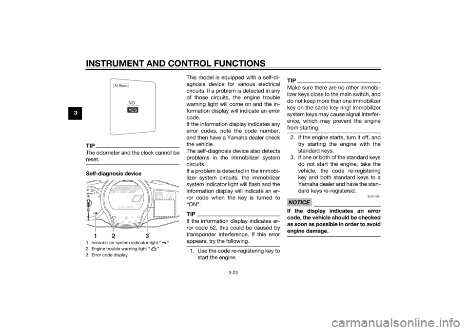
reset.Self-diagnosis device This model is equipped with a self-di-
agnosis device for various electrical
circuits. If a problem is detected in any
of those circuits, the engine trouble
warning light will come on and the in-
formation display will indicate an error
code.
If the information display indicates any
error codes, note the code number,
and then have a Yamaha dealer check
the vehicle.
The self-diagnosis device also detects
problems in the immobilizer system
circuits.
If a problem is detected in the immobi-
lizer system circuits, the immobilizer
system indicator light will flash and the
information display will indicate an er-
ror code when the key is turned to
“ON”.
TIPIf the information display indicates er-
ror code 52, this could be caused by
transponder interference. If this error
appears, try the following.1. Use the code re-registering key to
start the engine.
TIPMake sure there are no other immobi-
lizer keys close to the main switch, and
do not keep more than one immobilizer
key on the same key ring! Immobilizer
system keys may cause signal interfer-
ence, which may prevent the engine
from starting.2. If the engine starts, turn it off, andtry starting the engine with the
standard keys.
3. If one or both of the standard keys do not start the engine, take the
vehicle, the code re-registering
key and both standard keys to a
Yamaha dealer and have the stan-
dard keys re-registered.NOTICE
ECA11591
If the display in dicates an error
co de, the vehicle shoul d b e checked
as soon as possi ble in or der to avoi d
en gine damag e.
1. Immobilizer system indicator light “ ”
2. Engine trouble warning light “ ”
3. Error code display
All Reset
YESNO
GEARN
25
A.TEMP ˚C
Lo
C.TEMP˚C
0:06
TIME TRIP
1
2
3
U2PDE1E0.book Page 23 Thursday, July 10, 2014 5:19 PM
Page 72 of 122

PERIODIC MAINTENANCE AND ADJUSTMENT
6-3
6
EAU46862
TIPThe annual checks must b e performed every year, except if a kilometer- based maintenance, or for the UK, a
milea ge- based maintenance, is performed instead.
From 50000 km (30000 mi), repeat the maintenance intervals starting from 10000 km (6000 mi).
Items marked with an asterisk should be performed by a Yamaha dealer as they require special tools, data and tech-
nical skills.
EAU46911
Perio dic maintenance chart for the emission control systemNO. ITEM CHECK OR MAINTENANCE JOB ODOMETER READING
ANNUAL
CHECK
1000 km
(600 mi) 10000 km
(6000 mi) 20000 km
(12000 mi) 30000 km
(18000 mi) 40000 km
(24000 mi)
1 *Fuel line • Check fuel hoses for cracks or
damage. √√√√√
2 *Spark plu gs • Check condition.
• Clean and regap.
√√
• Replace. √√
3 *Va l ve s • Check valve clearance.
•Adjust.
Every 40000 km (24000 mi)
4 *Fuel injection sys-
tem • Adjust synchronization.
√√√√√√
5 *Mufflers an
d ex-
haust pipes • Check the screw clamps for
looseness. √√√√√
6 *Air in
duction sys-
tem • Check the air cut-off valve, reed
valve, and hose for damage.
• Replace any damaged parts if necessary. √√√√√
U2PDE1E0.book Page 3 Thursday, July 10, 2014 5:19 PM
Page 73 of 122

PERIODIC MAINTENANCE AND ADJUSTMENT
6-4
6
EAU1770K
General maintenance and lu brication chartNO. ITEM CHECK OR MAINTENANCE JOB ODOMETER READING
ANNUAL
CHECK
1000 km
(600 mi) 10000 km
(6000 mi) 20000 km
(12000 mi) 30000 km
(18000 mi) 40000 km
(24000 mi)
1 Air filter element • Clean.
√√
•Replace. √√
2 *Clutch • Check operation, fluid level and
vehicle for fluid leakage. √√√√√
3 *Front brake • Check operation, fluid level and
vehicle for fluid leakage. √√√√√√
• Replace brake pads. Whenever worn to the limit
4 *Rear brake • Check operation, fluid level and
vehicle for fluid leakage. √√√√√√
• Replace brake pads. Whenever worn to the limit
5 *Brake hoses • Check for cracks or damage.
• Check for correct routing and
clamping. √√√√√
• Replace. Every 4 years
6 *Brake fluid • Replace. Every 2 years
7 *Wheels • Check runout and for damage. √√√√
8 *Tires • Check tread depth and for dam-
age.
• Replace if necessary.
• Check air pressure.
• Correct if necessary. √√√√√
9 *Wheel bearin gs • Check bearings for looseness or
damage. √√√√
U2PDE1E0.book Page 4 Thursday, July 10, 2014 5:19 PM
Page 74 of 122

PERIODIC MAINTENANCE AND ADJUSTMENT
6-5
6
10*Swin garm • Check operation and for exces-
sive play. √√√√
• Lubricate with lithium-soap- based grease. Every 50000 km (30000 mi)
11 *Steerin g b earin gs • Check bearing play and steering
for roughness. √√√√√
• Lubricate with lithium-soap- based grease. Every 20000 km (12000 mi)
12 *Chassis fasteners • Make sure that all nuts, bolts and
screws are properly tightened. √√√√√
13 Brake lever pivot
shaft • Lubricate with silicone grease.
√√√√√
14 Brake ped
al pivot
shaft • Lubricate with lithium-soap-
based grease. √√√√√
15 Clutch lever pivot
shaft
• Lubricate with silicone grease.
√√√√√
16 Shift ped
al pivot
shaft • Lubricate with lithium-soap-
based grease. √√√√√
17 Si
destan d, center-
stan d • Check operation.
• Lubricate with lithium-soap-
based grease. √√√√√
18 *Sidestan d switch • Check operation. √√√√√√
19 *Front fork • Check operation and for oil leak-
age. √√√√
20 *Shock a
bsor ber as-
sem bly • Check operation and shock ab-
sorber for oil leakage. √√√√
NO. ITEM CHECK OR MAINTENANCE JOB
ODOMETER READING
ANNUAL
CHECK
1000 k
m
(600 mi) 10000 km
(6000 mi) 20000 km
(12000 mi) 30000 km
(18000 mi) 40000 km
(24000 mi)
U2PDE1E0.book Page 5 Thursday, July 10, 2014 5:19 PM
Page 75 of 122

PERIODIC MAINTENANCE AND ADJUSTMENT
6-6
6
21*Rear suspension re-
lay arm an
d con-
nectin g arm
pivotin g points • Check operation.
√√√√
• Lubricate with lithium-soap- based grease. √√
22 En gine oil • Change.
• Check oil level and vehicle for oil
leakage. √√√√√√
23 En
gine oil filter car-
tri dg e •Replace.
√√√
24 *Coolin g system • Check coolant level and vehicle
for coolant leakage. √√√√√
• Change coolant. Every 3 years
25 Final gear oil • Check oil level and vehicle for oil
leakage.
• Change. √√√√√
26 *Front an
d rear
b rake switches • Check operation.
√√√√√√
27 Movin
g parts an d
ca bles • Lubricate.
√√√√√
28 *Throttle g rip • Check operation.
• Check throttle grip free play, and
adjust if necessary.
• Lubricate cable and grip housing. √√√√√
29 *Li
ghts, si gnals an d
switches • Check operation.
• Adjust headlight beam.
√√√√√√
NO. ITEM CHECK OR MAINTENANCE JOB
ODOMETER READING
ANNUAL
CHECK
1000 km
(600 mi) 10000 km
(6000 mi) 20000 km
(12000 mi) 30000 km
( 18
000 mi)40000 km
(24000 mi)
U2PDE1E0.book Page 6 Thursday, July 10, 2014 5:19 PM