clutch YAMAHA FJR1300AS 2015 User Guide
[x] Cancel search | Manufacturer: YAMAHA, Model Year: 2015, Model line: FJR1300AS, Model: YAMAHA FJR1300AS 2015Pages: 124, PDF Size: 3.39 MB
Page 79 of 124
PERIODIC MAINTENANCE AND ADJUSTMENT
6-7
6
EAU40551
TIPThe air filter needs more frequent service if you are riding in unusually wet or dusty areas.
Hydraulic brake and YCC-S clutch service
• Regularly check and, if necessary, correct the brake and YCC-S clutch fluid levels.
• Every two years replace the internal components of the brake master cylinders and calipers as well as YCC-S clutch
master and release cylinders, and change the brake and YCC-S clutch fluids.
• Replace the brake and YCC-S clutch hoses every four years and if cracked or damaged.
U1MDE1E0.book Page 7 Monday, July 28, 2014 10:48 AM
Page 86 of 124
PERIODIC MAINTENANCE AND ADJUSTMENT
6-14
6
NOTICE
ECA11621
In order to prevent clutch slip-
page (since the engine oil also
lubricates the clutch), do not
mix any chemical additives. Do
not use oils with a diesel speci-
fication of “CD” or oils of a high-
er quality than specified. In
addition, do not use oils labeled
“ENERGY CONSERVING II” or
higher.
Make sure that no foreign mate-
rial enters the crankcase.10. Start the engine, and then let it idle
for several minutes while checking
it for oil leakage. If oil is leaking,
immediately turn the engine off
and check for the cause.TIPAfter the engine is started, the engine
oil level warning light should go off if
the oil level is sufficient.
NOTICE
ECA10402
If the oil level warning light flickers
or remains on even if the oil level is
correct, immediately turn the engine
off and have a Yamaha dealer check
the vehicle.11. Turn the engine off, and then
check the oil level and correct it if
necessary.
EAU20017
Final gear oilThe final gear case must be checked
for oil leakage before each ride. If any
leakage is found, have a Yamaha deal-
er check and repair the vehicle. In ad-
dition, the final gear oil level must be
checked and the oil changed as fol-
lows at the intervals specified in the
periodic maintenance and lubrication
chart.
WARNING
EWA10371
Make sure that no foreign mate-
rial enters the final gear case.
Make sure that no oil gets on
the tire or wheel.To check the final gear oil level
1. Place the vehicle on the center-
stand.TIPMake sure that the vehicle is posi-
tioned straight up when checking the
oil level. A slight tilt to the side can re-
sult in a false reading.
U1MDE1E0.book Page 14 Monday, July 28, 2014 10:48 AM
Page 93 of 124
PERIODIC MAINTENANCE AND ADJUSTMENT
6-21
6
EAU21963
Cast wheelsTo maximize the performance, durabil-
ity, and safe operation of your vehicle,
note the following points regarding the
specified wheels.
The wheel rims should be
checked for cracks, bends, warp-
age or other damage before each
ride. If any damage is found, have
a Yamaha dealer replace the
wheel. Do not attempt even the
smallest repair to the wheel. A de-
formed or cracked wheel must be
replaced.
The wheel should be balanced
whenever either the tire or wheel
has been changed or replaced. An
unbalanced wheel can result in
poor performance, adverse han-
dling characteristics, and a short-
ened tire life.
EAU40621
YCC-S clutchThis model is equipped with a hydrau-
lic clutch, therefore, it is necessary to
check the YCC-S clutch fluid level and
check the hydraulic system for leakage
before each ride. If the YCC-S clutch
plates wear out, shifting becomes
rough or clutch slippage will occur,
causing poor acceleration. If any of the
above occurs, have a Yamaha dealer
check the YCC-S clutch.
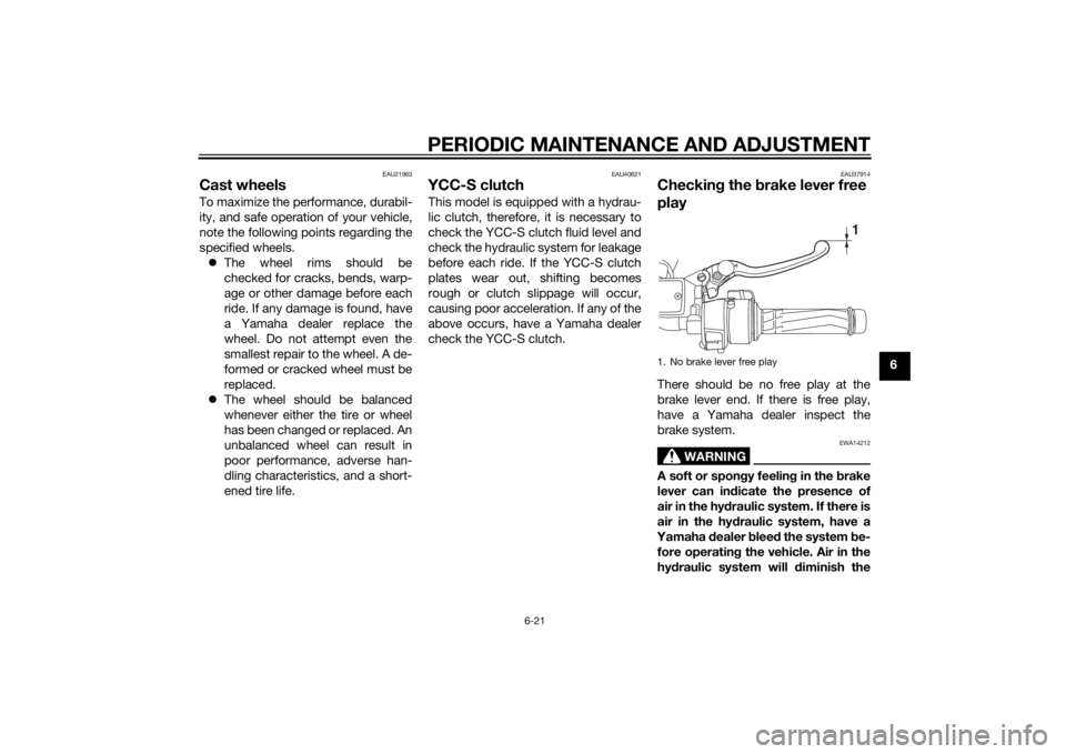
EAU37914
Checking the brake lever free
playThere should be no free play at the
brake lever end. If there is free play,
have a Yamaha dealer inspect the
brake system.
WARNING
EWA14212
A soft or spongy feeling in the brake
lever can indicate the presence of
air in the hydraulic system. If there is
air in the hydraulic system, have a
Yamaha dealer bleed the system be-
fore operating the vehicle. Air in the
hydraulic system will diminish the1. No brake lever free play
1
U1MDE1E0.book Page 21 Monday, July 28, 2014 10:48 AM
Page 95 of 124
PERIODIC MAINTENANCE AND ADJUSTMENT
6-23
6 indicator groove has almost disap-
peared, have a Yamaha dealer replace
the brake pads as a set.
EAU22501
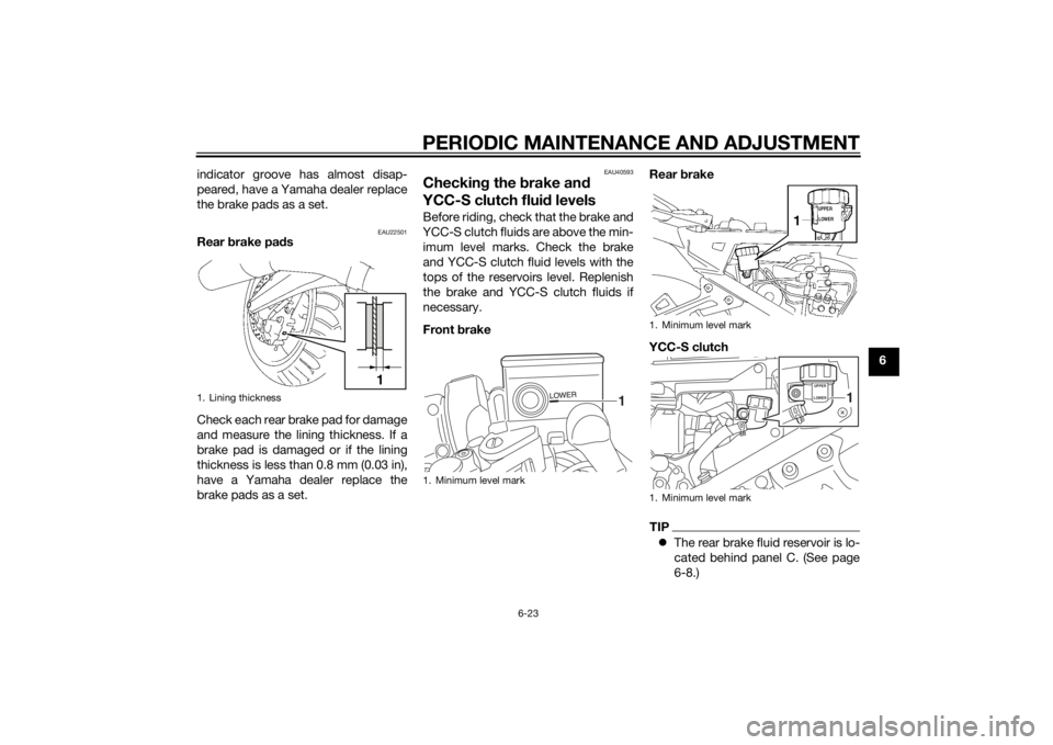
Rear brake pads
Check each rear brake pad for damage
and measure the lining thickness. If a
brake pad is damaged or if the lining
thickness is less than 0.8 mm (0.03 in),
have a Yamaha dealer replace the
brake pads as a set.
EAU40593
Checking the brake and
YCC-S clutch fluid levelsBefore riding, check that the brake and
YCC-S clutch fluids are above the min-
imum level marks. Check the brake
and YCC-S clutch fluid levels with the
tops of the reservoirs level. Replenish
the brake and YCC-S clutch fluids if
necessary.
Front brakeRear brake
YCC-S clutch
TIPThe rear brake fluid reservoir is lo-
cated behind panel C. (See page
6-8.)
1. Lining thickness
1
1. Minimum level mark
1
1. Minimum level mark
1. Minimum level mark
UPPER
LOWER
1
U1MDE1E0.book Page 23 Monday, July 28, 2014 10:48 AM
Page 96 of 124
PERIODIC MAINTENANCE AND ADJUSTMENT
6-24
6The YCC-S clutch fluid reservoir is
located behind panel B. (See page
6-8.)
WARNING
EWA16021
Improper maintenance can result in
loss of braking ability or YCC-S
clutch operation. Observe these
precautions:
Insufficient brake or YCC-S
clutch fluid may allow air to en-
ter the brake or YCC-S clutch
system, reducing braking or
YCC-S clutch performance.
Clean the filler caps before re-
moving. Use only DOT 4 brake
fluid from a sealed container.
Use only the specified brake flu-
id; otherwise, the rubber seals
may deteriorate, causing leak-
age.Refill with the same type of
brake fluid. Adding a brake fluid
other than DOT 4 may result in a
harmful chemical reaction.
Be careful that water or dust
does not enter the brake or
YCC-S clutch fluid reservoir
when refilling. Water will signifi-
cantly lower the boiling point of
the fluid
and may result in vapor
lock, and dirt may clog the ABS
hydraulic unit valves.
NOTICE
ECA17641
Brake fluid may damage painted
surfaces or plastic parts. Always
clean up spilled fluid immediately.The brake and YCC-S clutch fluid res-
ervoir diaphragms will lose their shape
from the negative pressure if the fluid
level goes down too far. Be sure to re-
turn the diaphragms to their original
shape before reinstalling them.
As the brake pads wear, it is normal for
the brake fluid level to gradually go
down. A low brake fluid level may indi-
cate worn brake pads and/or brake
system leakage; therefore, be sure tocheck the brake pads for wear and the
brake system for leakage. A low
YCC-S clutch fluid level may indicate
YCC-S clutch system leakage; there-
fore, be sure to check the YCC-S
clutch system for leakage. If the brake
or YCC-S clutch fluid level goes down
suddenly, have a Yamaha dealer check
the cause before further riding.
Specified brake and YCC-S clutch
fluid:
DOT 4 brake fluid
U1MDE1E0.book Page 24 Monday, July 28, 2014 10:48 AM
Page 97 of 124
PERIODIC MAINTENANCE AND ADJUSTMENT
6-25
6
EAU40603
Changing the brake and
YCC-S clutch fluidsHave a Yamaha dealer change the
brake and YCC-S clutch fluids at the
intervals specified in the periodic main-
tenance and lubrication chart or in the
TIP after the periodic maintenance and
lubrication chart. In addition, have the
oil seals of the brake and YCC-S clutch
master cylinders and calipers as well
as the brake and YCC-S clutch hoses
replaced at the intervals listed below or
whenever they are damaged or leak-
ing.
Oil seals: Replace every two
years.
Brake and YCC-S clutch hoses:
Replace every four years.
EAU23098
Checking and lubricating the
cablesThe operation of all control cables and
the condition of the cables should be
checked before each ride, and the ca-
bles and cable ends should be lubri-
cated if necessary. If a cable is
damaged or does not move smoothly,
have a Yamaha dealer check or re-
place it. WARNING! Damage to the
outer housing of cables may result
in internal rusting and cause inter-
ference with cable movement. Re-
place damaged cables as soon as
possible to prevent unsafe condi-
tions.
[EWA10712]EAU23115
Checking and lubricating the
throttle grip and cableThe operation of the throttle grip
should be checked before each ride. In
addition, the cable should be lubricat-
ed by a Yamaha dealer at the intervals
specified in the periodic maintenance
chart.
The throttle cable is equipped with a
rubber cover. Make sure that the cover
is securely installed. Even though the
cover is installed correctly, it does not
completely protect the cable from wa-
ter entry. Therefore, use care not to
pour water directly onto the cover or
cable when washing the vehicle. If the
cable or cover becomes dirty, wipe
clean with a moist cloth.
Recommended lubricant:
Yamaha cable lubricant or other
suitable cable lubricant
U1MDE1E0.book Page 25 Monday, July 28, 2014 10:48 AM
Page 115 of 124
SPECIFICATIONS
8-1
8
Dimensions:Overall length:
2230 mm (87.8 in)
Overall width:
750 mm (29.5 in)
Overall height:
1325/1455 mm (52.2/57.3 in)
Seat height:
805/825 mm (31.7/32.5 in)
Wheelbase:
1545 mm (60.8 in)
Ground clearance:
123 mm (4.84 in)
Minimum turning radius:
3200 mm (126.0 in)Weight:Curb weight:
296 kg (653 lb)Engine:Engine type:
Liquid cooled 4-stroke, DOHC
Cylinder arrangement:
Inline 4-cylinder
Displacement:
1298 cm³
Bore × stroke:
79.0 × 66.2 mm (3.11 × 2.61 in)
Compression ratio:
10.8 : 1
Starting system:
Electric starter
Lubrication system:
Wet sump
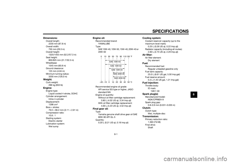
Engine oil:Recommended brand:
YAMALUBE
Type:
SAE 10W-40, 10W-50, 15W-40, 20W-40 or
20W-50
Recommended engine oil grade:
API service SG type or higher, JASO
standard MA
Engine oil quantity:
Without oil filter cartridge replacement:
3.80 L (4.02 US qt, 3.34 Imp.qt)
With oil filter cartridge replacement:
4.00 L (4.23 US qt, 3.52 Imp.qt)Final gear oil:Type:
Yamaha genuine shaft drive gear oil SAE
80W-90 API GL-5
Quantity:
0.20 L (0.21 US qt, 0.18 Imp.qt)
Cooling system:Coolant reservoir capacity (up to the
maximum level mark):
0.25 L (0.26 US qt, 0.22 Imp.qt)
Radiator capacity (including all routes):
2.60 L (2.75 US qt, 2.29 Imp.qt)Air filter:Air filter element:
Dry elementFuel:Recommended fuel:
Regular unleaded gasoline only
Fuel tank capacity:
25.0 L (6.61 US gal, 5.50 Imp.gal)
Fuel reserve amount:
5.5 L (1.45 US gal, 1.21 Imp.gal)Fuel injection:Throttle body:
ID mark:
1MC1 00Spark plug(s):Manufacturer/model:
NGK/CPR8EA-9
Spark plug gap:
0.8–0.9 mm (0.031–0.035 in)Clutch:Clutch type:
Wet, multiple-discTransmission:Primary reduction ratio:
1.563 (75/48)
Final drive:
Shaft
–20 –10 0
1020 30 40 50 C 10 30 50 70 90 110 0 130 F
SAE 20W-50SAE 20W-40SAE 15W-40SAE 10W-40SAE 10W-50
U1MDE1E0.book Page 1 Monday, July 28, 2014 10:48 AM
Page 120 of 124
10-1
10
INDEXAABS ....................................................... 3-30
ABS warning light ................................... 3-5
Accessory box ...................................... 3-39
Air filter element .................................... 6-17
Auxiliary DC jack ................................... 3-49
Auxiliary light......................................... 6-32BBattery .................................................. 6-29
Brake and shift pedals, checking and
lubricating ........................................... 6-26
Brake and YCC-S clutch fluid levels,
checking ............................................. 6-23
Brake and YCC-S clutch fluids,
changing ............................................. 6-25
Brake lever ............................................ 3-29
Brake lever, checking and lubricating .. 6-26
Brake lever free play, checking............. 6-21
Brake light switches.............................. 6-22
Brake pedal........................................... 3-29CCables, checking and lubricating ......... 6-25
Care ........................................................ 7-1
Catalytic converters .............................. 3-34
Centerstand and sidestand, checking
and lubricating .................................... 6-27
Coolant ................................................. 6-16
Cowling vents, opening and closing ..... 3-40
Cruise control indicator lights ................. 3-4
Cruise control switches ........................ 3-26
Cruise control system ............................. 3-7DDimmer/Pass switch ............................. 3-26
D-mode (drive mode) ............................ 3-25
EElectronically adjustable suspension
system warning light ............................ 3-6
Engine break-in ...................................... 5-4
Engine idling speed, checking ............. 6-17
Engine oil and oil filter cartridge ........... 6-12
Engine serial number .............................. 9-1
Engine trouble warning light ................... 3-4FFinal gear oil ......................................... 6-14
Front and rear brake pads, checking ... 6-22
Front fork, checking ............................. 6-28
Front turn signal light............................ 6-33
Fuel ....................................................... 3-33
Fuel consumption, tips for reducing ...... 5-4
Fuel tank breather/overflow hose ......... 3-34
Fuel tank cap ........................................ 3-32
Fuses, replacing ................................... 6-31HHandlebar position, adjusting .............. 3-40
Handlebar switches .............................. 3-25
Hand shift lever .................................... 3-29
Hazard switch....................................... 3-26
Headlight beams, adjusting.................. 3-40
Headlight bulb ...................................... 6-32
High beam indicator light ....................... 3-4
Horn switch .......................................... 3-26IIdentification numbers ............................ 9-1
Ignition circuit cut-off system ............... 3-47
Immobilizer system ................................ 3-1
Immobilizer system indicator light .......... 3-7
Indicator lights and warning lights ......... 3-4
LLicense plate light bulb, replacing ........6-34MMain switch/steering lock .......................3-2
Maintenance and lubrication, periodic....6-4
Maintenance, emission control
system ..................................................6-3
Matte color, caution ................................7-1
Menu switch..........................................3-26
Model label .............................................9-1
Multi-function meter unit .......................3-11NNeutral indicator light ..............................3-4OOil level warning light ..............................3-4PPanels, removing and installing ..............6-8
Parking ....................................................5-5
Part locations ..........................................2-1RRear suspension, lubricating ................6-27
Rear view mirrors ..................................3-42
Rider seat height, adjusting ..................3-36SSafety information ...................................1-1
Seats .....................................................3-35
Select switch.........................................3-27
Shift down indicator light ........................3-6
Shifting ....................................................5-3
Shift pedal .............................................3-28
Sidestand ..............................................3-46
Spark plugs, checking ..........................6-11
Specifications .........................................8-1
Start/Engine stop switch .......................3-26
U1MDE1E0.book Page 1 Monday, July 28, 2014 10:48 AM
Page 121 of 124
INDEX
10-2
10
Starting the engine ................................. 5-1
Steering, checking ................................ 6-29
Stop mode function indicator light ......... 3-7
Stop mode function switch .................. 3-27
Storage ................................................... 7-4
Storage compartment .......................... 3-38
Suspension, adjusting the front and
rear ..................................................... 3-42
Swingarm pivots, lubricating ................ 6-28TThrottle grip and cable, checking and
lubricating........................................... 6-25
Throttle grip free play, checking ........... 6-18
Tires ...................................................... 6-18
Tool kit .................................................... 6-2
Traction control system ........................ 3-31
Traction control system indicator/
warning light ......................................... 3-5
Troubleshooting.................................... 6-34
Troubleshooting charts......................... 6-36
Turn signal indicator lights ..................... 3-4
Turn signal light or tail/brake light bulb,
replacing............................................. 6-33
Turn signal switch................................. 3-26VValve clearance .................................... 6-18
Vehicle identification number ................. 9-1WWheel bearings, checking .................... 6-29
Wheels .................................................. 6-21YYCC-S clutch........................................ 6-21
YCC-S system ...................................... 3-27
YCC-S system warning light .................. 3-6
U1MDE1E0.book Page 2 Monday, July 28, 2014 10:48 AM