Battery YAMAHA FX HO CRUISER 2022 Owners Manual
[x] Cancel search | Manufacturer: YAMAHA, Model Year: 2022, Model line: FX HO CRUISER, Model: YAMAHA FX HO CRUISER 2022Pages: 136, PDF Size: 5.62 MB
Page 8 of 136
Table of contents
Regulatory information confirmation (“Regulatory Info”)......................... 63
Engine lock screen ....................... 63
Warning function ........................... 64
Audio system (equipped models) ...................................... 66
Audio control .................................... 66
Voice command ............................... 67
Accessory outlet ........................... 68
USB charger.................................. 68
Equipment operation ...................... 69 Equipment ..................................... 69
Seats ................................................ 69
Handgrip .......................................... 70
Reboarding grip ............................... 70
Reboarding step............................... 70
Bow eye ........................................... 71
Stern eyes ........................................ 71
Cleat ................................................. 71
Dual Rope Hooks ............................. 72
Storage compartments .................... 72
Fire extinguisher holder and cover ... 75
Operation and handling
requirements ................................... 77Fuel requirements ......................... 77
Fuel................................................... 77
Engine oil requirements ................ 79
Engine oil .......................................... 79
Draining the bilge water ................ 81
Draining the bilge water on land ...... 81
Draining the bilge water on water .... 81
Transporting on a trailer ................ 82
First-time operation ........................ 83 Engine break-in ............................. 83
Pre-operation checks ..................... 84
Pre-operation checklist .................... 84
Pre-operation check points........... 86
Pre-launch checks ........................... 86
Post-launch checks ......................... 92
Operation ......................................... 93 Operating your watercraft ............. 93
Getting to know your watercraft....... 93
Learning to operate your
watercraft ...................................... 93
Riding position ................................. 94
Launching the watercraft ................. 94
Starting the engine on water ............ 94
Stopping the engine ......................... 95
Leaving the watercraft ...................... 95
Operating the watercraft .................. 95
Turning the watercraft ...................... 96
Stopping the watercraft.................... 97
Operating the watercraft in reverse or neutral ...................................... 98
Boarding the watercraft.................... 99
Starting off...................................... 101
Capsized watercraft ....................... 102
Beaching and docking the
watercraft .................................... 103
Operating in weeded areas ............ 103
After removing the watercraft from the water ............................. 104
Care and storage .......................... 105Post-operation care .................... 105
Flushing the cooling water
passages..................................... 105
Cleaning the watercraft .................. 106
Battery care .................................... 106
Long-term storage ...................... 108
Cleaning ......................................... 108
Lubrication ..................................... 108
Rustproofing ................................... 109
Maintenance .................................. 110 Maintenance ............................... 110
Removing and installing the
engine cover ............................... 110
Periodic maintenance chart ........... 112
Engine oil and oil filter .................... 114
UF3V73E0.book Page 2 Friday, October 8, 2021 1:30 PM
Page 9 of 136
Table of contents
Specifications ................................ 115Specifications.............................. 115
Trouble recovery ........................... 117 Troubleshooting .......................... 117
Troubleshooting chart .................... 117
Emergency procedures ............... 120
Cleaning the jet intake and
impeller ....................................... 120
Raising the reverse gate ................ 121
Jumping the battery ....................... 121
Towing the watercraft .................... 122
Submerged watercraft ................... 122
Index ............................................... 124
UF3V73E0.book Page 3 Friday, October 8, 2021 1:30 PM
Page 32 of 136
Description
23
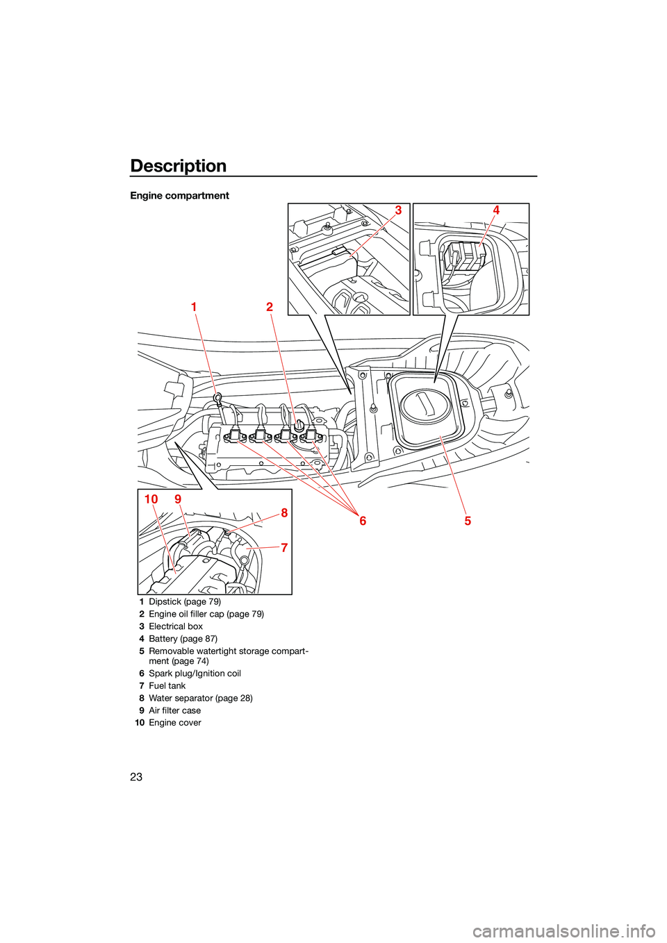
Engine compartment
12
5
7
8
9106
43
1Dipstick (page 79)
2 Engine oil filler cap (page 79)
3 Electrical box
4 Battery (page 87)
5 Removable watertight storage compart-
ment (page 74)
6 Spark plug/Ignition coil
7 Fuel tank
8 Water separator (page 28)
9 Air filter case
10 Engine cover
UF3V73E0.book Page 23 Friday, October 8, 2021 1:30 PM
Page 49 of 136
Instrument operation
40
EJU46620
Multifunction information center
The multifunction information center displays
various watercraft information.
The multifunction information center is a
touch screen that you can touch directly to
turn the various functions on or off or change
settings. You can also perform operations
using the touchpad control.
The language and display units shown can be
changed. (See page 55 for information on
changing the language and display units.) In
the illustrations in this manual, English is used
for the language and US units are used for the
display units.
EWJ01980
For safety, do not touch the multifunction
information center while the watercraft is
moving. Otherwise, you could lose control
of the watercraft, which may lead to an ac-
cident.
TIP
The multifunction information center does not
receive operation input while the watercraft is
moving. Before operating the multifunction
information center, stop the watercraft and
check the area around you to make sure it is
safe to operate the center.
Turning on the multifunction information
center
When the engine start/stop switch is pushed,
the multifunction information center turns on.
After the logo is displayed for a few seconds
followed by a disclaimer, select “CONFIRM”
to display the home screen.
TIP
The multifunction information center is turned
on, even if the engine start/stop switch is also
pushed briefly.
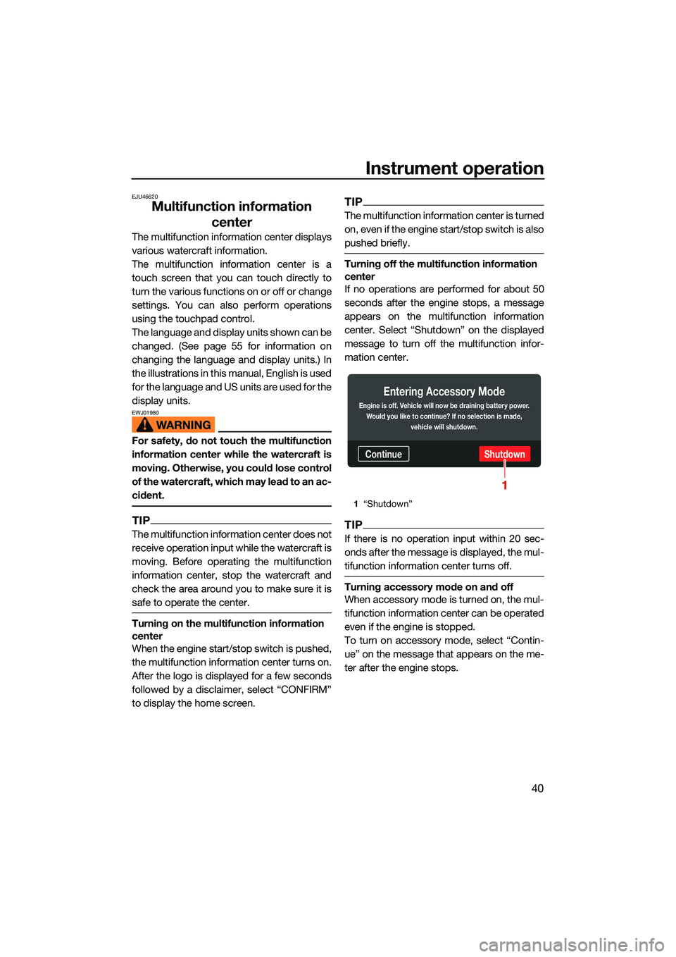
Turning off the multifunction information
center
If no operations are performed for about 50
seconds after the engine stops, a message
appears on the multifunction information
center. Select “Shutdown” on the displayed
message to turn off the multifunction infor-
mation center.
TIP
If there is no operation input within 20 sec-
onds after the message is displayed, the mul-
tifunction information center turns off.
Turning accessory mode on and off
When accessory mode is turned on, the mul-
tifunction information center can be operated
even if the engine is stopped.
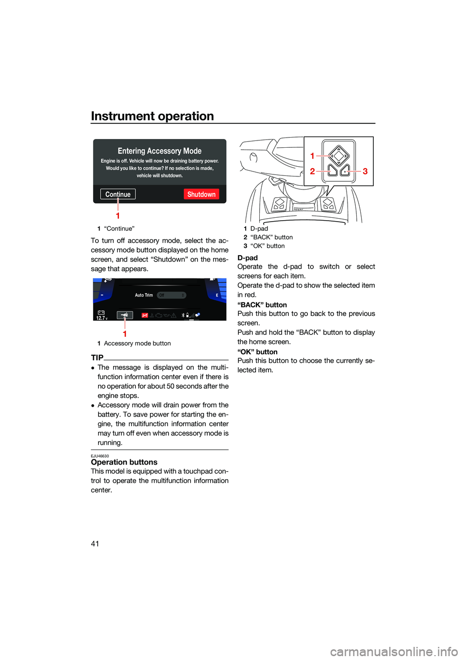
To turn on accessory mode, select “Contin-
ue” on the message that appears on the me-
ter after the engine stops.
1 “Shutdown”
ContinueShutdown
Entering Accessory Mode
Engine is off. Vehicle will now be draining battery power.
Would you like to continue? If no selection is made, vehicle will shutdown.
1
UF3V73E0.book Page 40 Friday, October 8, 2021 1:30 PM
Page 50 of 136
Instrument operation
41
To turn off accessory mode, select the ac-
cessory mode button displayed on the home
screen, and select “Shutdown” on the mes-
sage that appears.
TIP
The message is displayed on the multi-
function information center even if there is
no operation for about 50 seconds after the
engine stops.
Accessory mode will drain power from the
battery. To save power for starting the en-
gine, the multifunction information center
may turn off even when accessory mode is
running.
EJU46630Operation buttons
This model is equipped with a touchpad con-
trol to operate the multifunction information
center.D-pad
Operate the d-pad to switch or select
screens for each item.
Operate the d-pad to show the selected item
in red.
“BACK” button
Push this button to go back to the previous
screen.
Push and hold the “BACK” button to display
the home screen.
“OK” button
Push this button to choose the currently se-
lected item.
1
“Continue”
1 Accessory mode button
ContinueShutdown
Entering Accessory Mode
Engine is off. Vehicle will now be draining battery power.
Would you like to continue? If no selection is made, vehicle will shutdown.
1
Auto TrimOff
12.7V2
1
1D-pad
2 “BACK” button
3 “OK” button
1
23
UF3V73E0.book Page 41 Friday, October 8, 2021 1:30 PM
Page 51 of 136
Instrument operation
42
EJU46641
Display
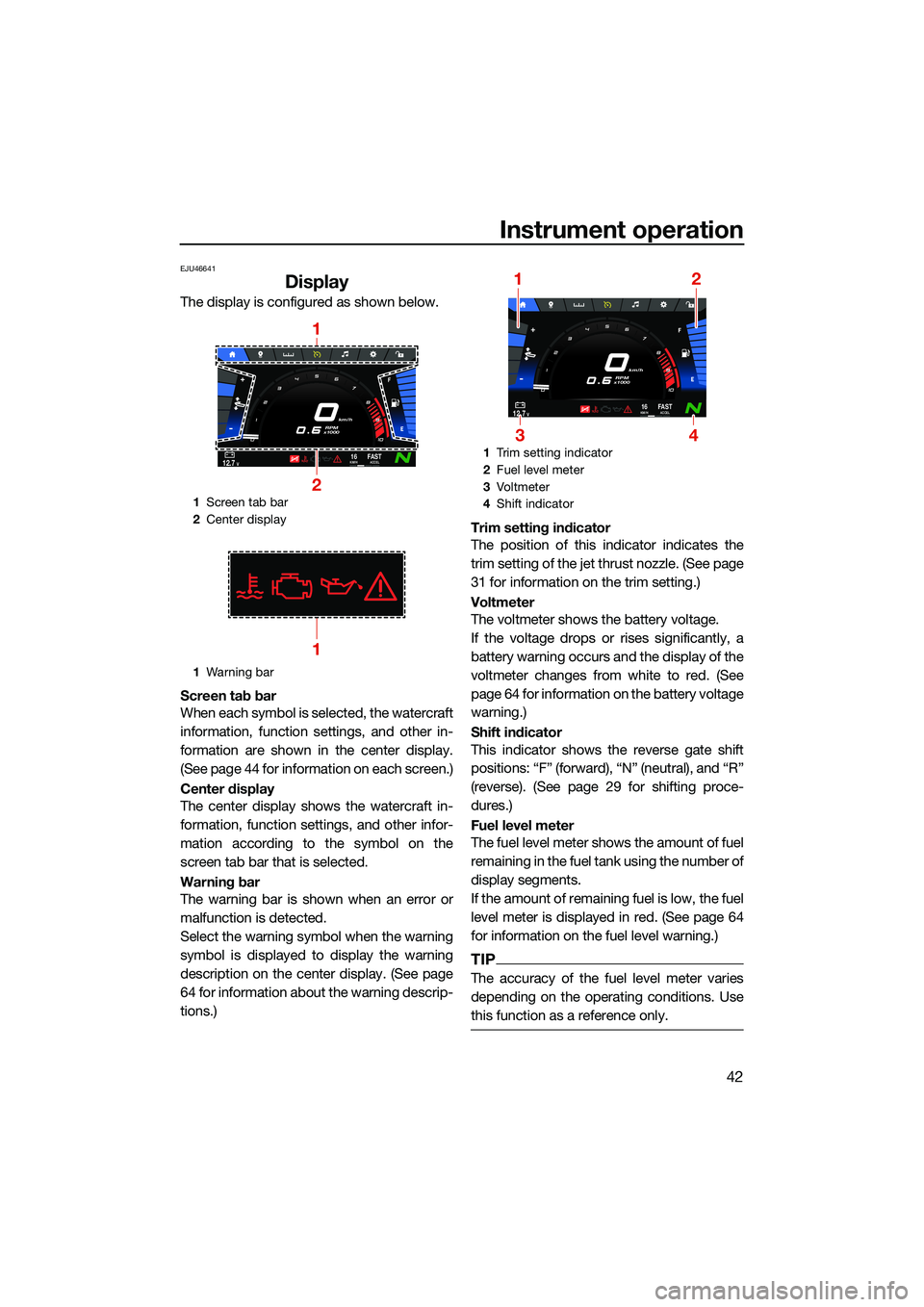
The display is configured as shown below.
Screen tab bar
When each symbol is selected, the watercraft
information, function settings, and other in-
formation are shown in the center display.
(See page 44 for information on each screen.)
Center display
The center display shows the watercraft in-
formation, function settings, and other infor-
mation according to the symbol on the
screen tab bar that is selected.
Warning bar
The warning bar is shown when an error or
malfunction is detected.
Select the warning symbol when the warning
symbol is displayed to display the warning
description on the center display. (See page
64 for information about the warning descrip-
tions.)Trim setting indicator
The position of this indicator indicates the
trim setting of the jet thrust nozzle. (See page
31 for information on the trim setting.)
Voltmeter
The voltmeter shows the battery voltage.
If the voltage drops or rises significantly, a
battery warning occurs and the display of the
voltmeter changes from white to red. (See
page 64 for information on the battery voltage
warning.)
Shift indicator
This indicator shows the reverse gate shift
positions: “F” (forward), “N” (neutral), and “R”
(reverse). (See page 29 for shifting proce-
dures.)
Fuel level meter
The fuel level meter shows the amount of fuel
remaining in the fuel tank using the number of
display segments.
If the amount of remaining fuel is low, the fuel
level meter is displayed in red. (See page 64
for information on the fuel level warning.)
TIP
The accuracy of the fuel level meter varies
depending on the operating conditions. Use
this function as a reference only.
1
Screen tab bar
2 Center display
1 Warning bar
km/h
RPM
x1000
12.7V16KM/HFA S TACCEL
1
2
1
1 Trim setting indicator
2 Fuel level meter
3 Vo l t m et e r
4 Shift indicator
km/h
RPM
x1000
12.7V16KM/HFA S TACCEL
12
34
UF3V73E0.book Page 42 Friday, October 8, 2021 1:30 PM
Page 73 of 136
Instrument operation
64
EJU46930
Warning function
The multifunction information center has the
following warning functions.
Fuel level warning
Battery voltage warning
Check engine warning
Engine overheat warning
Oil pressure warning
Other warnings (communication errors, ex-
ceeding the maintenance intervals, and so
on)
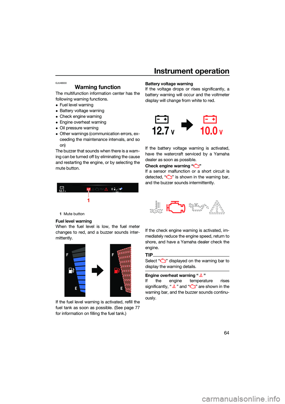
The buzzer that sounds when there is a warn-
ing can be turned off by eliminating the cause
and restarting the engine, or by selecting the
mute button.
Fuel level warning
When the fuel level is low, the fuel meter
changes to red, and a buzzer sounds inter-
mittently.
If the fuel level warning is activated, refill the
fuel tank as soon as possible. (See page 77
for information on filling the fuel tank.) Battery voltage warning
If the voltage drops or rises significantly, a
battery warning will occur and the voltmeter
display will change from white to red.
If the battery voltage warning is activated,
have the watercraft serviced by a Yamaha
dealer as soon as possible.
Check engine warning “ ”
If a sensor malfunction or a short circuit is
detected, “ ” is shown in the warning bar,
and the buzzer sounds intermittently.
If the check engine warning is activated, im-
mediately reduce the engine speed, return to
shore, and have a Yamaha dealer check the
engine.
TIP
Select “ ” displayed on the warning bar to
display the warning details.
Engine overheat warning “ ”
If the engine temperature rises
significantly, “ ” and “ ” are shown in the
warning bar, and the buzzer sounds continu-
ously.
1
Mute button
12.7V2
1
12.7V10.0V
UF3V73E0.book Page 64 Friday, October 8, 2021 1:30 PM
Page 77 of 136
Instrument operation
68
EJU46321
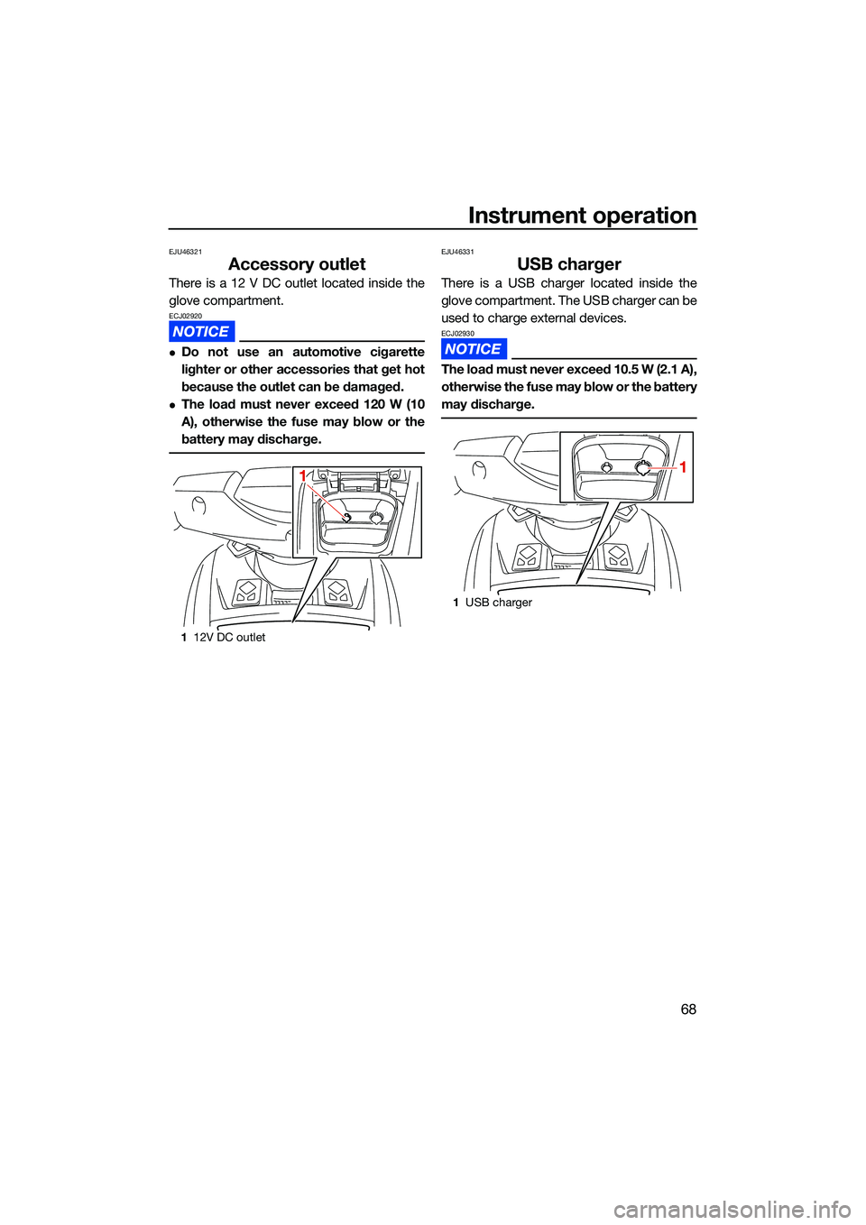
Accessory outlet
There is a 12 V DC outlet located inside the
glove compartment.
ECJ02920
Do not use an automotive cigarette
lighter or other accessories that get hot
because the outlet can be damaged.
The load must never exceed 120 W (10
A), otherwise the fuse may blow or the
battery may discharge.
EJU46331
USB charger
There is a USB charger located inside the
glove compartment. The USB charger can be
used to charge external devices.
ECJ02930
The load must never exceed 10.5 W (2.1 A),
otherwise the fuse may blow or the battery
may discharge.
112V DC outlet
11
1USB charger
1
UF3V73E0.book Page 68 Friday, October 8, 2021 1:30 PM
Page 93 of 136
Pre-operation checks
84
EJU31984
EWJ00413
Failure to inspect or maintain the watercraft properly increases the possibility of an ac-
cident or damage to the watercraft. Do not operate the watercraft if you find any prob-
lem. If a problem cannot be corrected by the procedures provided in this manual, have
the watercraft inspected by a Yamaha dealer.
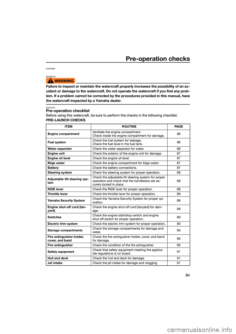
EJU41237Pre-operation checklist
Before using this watercraft, be sure to perform the checks in the following checklist.
PRE-LAUNCH CHECKS
ITEM ROUTINEPAGE
Engine compartment Ventilate the engine compartment.
Check inside the engine compartment for damage.
86
Fuel system Check the fuel system for leakage.
Check the fuel level in the fuel tank.
86
Water separator Check the water separator for water. 86
Engine unit Check the exterior of the engine unit for damage. 87
Engine oil level Check the engine oil level. 87
Bilge water Check the engine compartment for bilge water. 87
Battery Check the battery connections. 87
Steering system Check the steering system for proper operation. 88
Adjustable tilt steering sys-
tem Check the adjustable tilt steering system for proper
operation and check that the handlebars are se-
curely locked in place.
88
RiDE lever Check the RiDE lever for proper operation. 88
Throttle lever Check the throttle lever for proper operation. 89
Yamaha Security System Check the Yamaha Security System for proper op-
eration.
89
Engine shut-off cord (lan-
yard) Check the engine shut-off cord (lanyard) for dam-
age.
89
Switches Check the engine start/stop switch and engine
shut-off switch for proper operation.
89
Electric trim system Check the electric trim system for proper operation. 90
Storage compartments Check the storage compartments for damage and
water.
90
Fire extinguisher holder,
cover, and band Check the fire extinguisher holder, cover, and band
for damage.
90
Fire extinguisher Check the condition of the fire extinguisher. 90
Safety equipment Check that safety equipment meeting the applica-
ble regulations is on board.
91
Hull and deck Check the hull and deck for damage. 91
Jet intake Check the jet intake for damage and clogging. 91
UF3V73E0.book Page 84 Friday, October 8, 2021 1:30 PM
Page 96 of 136
Pre-operation checks
87
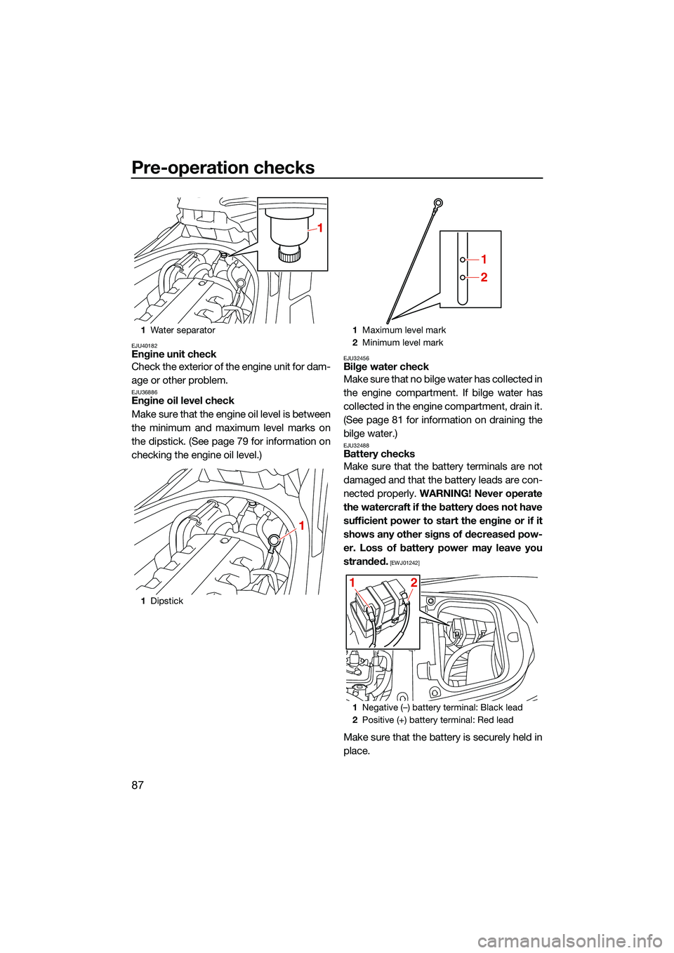
EJU40182Engine unit check
Check the exterior of the engine unit for dam-
age or other problem.
EJU36886Engine oil level check
Make sure that the engine oil level is between
the minimum and maximum level marks on
the dipstick. (See page 79 for information on
checking the engine oil level.)
EJU32456Bilge water check
Make sure that no bilge water has collected in
the engine compartment. If bilge water has
collected in the engine compartment, drain it.
(See page 81 for information on draining the
bilge water.)
EJU32488Battery checks
Make sure that the battery terminals are not
damaged and that the battery leads are con-
nected properly. WARNING! Never operate
the watercraft if the battery does not have
sufficient power to start the engine or if it
shows any other signs of decreased pow-
er. Loss of battery power may leave you
stranded.
[EWJ01242]
Make sure that the battery is securely held in
place.
1 Water separator
1 Dipstick
1
1
1Maximum level mark
2 Minimum level mark
1 Negative (–) battery terminal: Black lead
2 Positive (+) battery terminal: Red lead
1
2
12
UF3V73E0.book Page 87 Friday, October 8, 2021 1:30 PM