warning YAMAHA FX HO CRUISER 2022 Owners Manual
[x] Cancel search | Manufacturer: YAMAHA, Model Year: 2022, Model line: FX HO CRUISER, Model: YAMAHA FX HO CRUISER 2022Pages: 136, PDF Size: 5.62 MB
Page 5 of 136
Important manual information
EJU30193
To the owner/operator
Thank you for choosing a Yamaha watercraft.
This owner’s/operator’s manual contains in-
formation you will need for proper operation,
maintenance, and care. If you have any ques-
tions about the operation or maintenance of
your watercraft, please consult a Yamaha
dealer.
This manual is not a course on boating safety
or seamanship. If this is your first watercraft,
or if you are changing to a type of watercraft
you are not familiar with, for your own com-
fort and safety, please ensure that you obtain
proper training or practice before operating
the watercraft by yourself. In addition, a
Yamaha dealer or boating organization will be pleased to recommend local sea schools, or
competent instructors.
In this manual, information of particular im-
portance is distinguished in the following
ways:
This is the safety alert symbol. It is used
to alert you to potential personal injury haz-
ards. Obey all safety messages that follow
this symbol to avoid possible injury or death.
EWJ00072
A WARNING indicates a hazardous situa-
tion which, if not avoided, could result in
death or serious injury.
ECJ00092
A NOTICE indicates special precautions
that must be taken to avoid damage to the
watercraft or other property.
TIP
A TIP provides key information to make pro-
cedures easier or clearer.
EJU45451
Engine data recording
This model’s ECM stores certain engine data
to assist in the diagnosis of malfunctions and
for research, statistical analysis and develop-
ment purposes.
Although the sensors and recorded data will
vary by model, the main data points are:
Engine status and engine performance
data
This data will be uploaded only when a spe-
cial Yamaha diagnostic tool is attached to the
engine, such as when maintenance checks or
service procedures are performed. Engine
data uploaded will be handled appropriately
according to the following Privacy Policy.
Privacy Policy
Yamaha will not disclose this data to a third party except in the following cases. In addi-
tion, Yamaha may provide engine data to a
contractor in order to outsource services re-
lated to the handling of the engine data. Even
in this case, Yamaha will require the contrac-
tor to properly handle the engine data we
provided and Yamaha will appropriately
manage the data.
With the consent of the boat owner
Where obligated by law
For use by Yamaha in litigation
For general Yamaha-conducted research
purposes when the data is not related to an
individual engine or owner
https://www.yamaha-motor.eu/eu/
en/privacy/privacy-policy/
UF3V73E0.book Page 3 Friday, October 8, 2021 1:30 PM
Page 7 of 136
Table of contents
General and important labels ........... 1Identification numbers .................... 1
Primary Identification (PRI-ID)
number............................................ 1
Craft Identification Number (CIN) ....... 1
Engine serial number.......................... 1
Manufactured date label .................... 2
Model information ........................... 3
Builder’s plate .................................... 3
Important labels .............................. 4
Warning labels.................................... 5
Other labels ........................................ 8
Safety information ............................. 9 Limitations on who may operate the watercraft ............................... 9
Cruising limitations ........................ 10
Operation requirements ................ 11
Recommended equipment ........... 13
Hazard information........................ 14
Watercraft characteristics ............. 14
Wakeboarding and water-skiing ... 16
Safe boating rules ......................... 17
Enjoy your watercraft responsibly ................................. 18
Description....................................... 19 Watercraft glossary ....................... 19
Location of main components ...... 20
Control function operation ............. 24 Watercraft control functions ......... 24
Yamaha Security System ................. 24
Engine start/stop switch ................. 24
Engine shut-off switch .................... 25
Throttle lever .................................... 25
RiDE lever ........................................ 26
Steering system ............................... 26
Adjustable tilt steering system ......... 26
Cooling water pilot outlet ................. 27
Water separator................................ 28
Watercraft operation ...................... 29Watercraft operation functions ..... 29
Shift system ..................................... 29
Electric trim system .......................... 31
Watercraft operation modes ......... 33
Reverse assist .................................. 33
T.D.E. (thrust directional
enhancer) ...................................... 33
No-wake mode ................................. 34
Drive control mode ........................... 36
Cruise assist ..................................... 37
Instrument operation ...................... 40 Multifunction information center ... 40
Operation buttons ............................ 41
Display .......................................... 42
Display notification information ........ 43
Home screen ............................... 44
Map screen .................................. 45
Waypoint .......................................... 46
Track ................................................ 48
GeoFence ......................................... 51
Map settings .................................... 52
Information screen ....................... 52
Drive control mode screen .......... 53
Media screen (equipped models) ...................................... 54
Setting menu screen .................... 54
Changing the PIN (“PIN Settings”) ... 54
Display settings (“Display”) .............. 55
Selecting the display units (“Unit”) ... 55
Selecting the display language
(“Language”) ................................. 55
Display clock change (“Clock”) ........ 55
Displaying the time since the last
maintenance (“Wellness”) ............. 56
Notification settings
(“Notifications”) ............................. 57
Phone management (“Phone Manager”)........................ 57
Map settings (“Map Settings”) ......... 59
Return to factory settings (“Factory Reset”) ........................... 62
UF3V73E0.book Page 1 Friday, October 8, 2021 1:30 PM
Page 8 of 136
Table of contents
Regulatory information confirmation (“Regulatory Info”)......................... 63
Engine lock screen ....................... 63
Warning function ........................... 64
Audio system (equipped models) ...................................... 66
Audio control .................................... 66
Voice command ............................... 67
Accessory outlet ........................... 68
USB charger.................................. 68
Equipment operation ...................... 69 Equipment ..................................... 69
Seats ................................................ 69
Handgrip .......................................... 70
Reboarding grip ............................... 70
Reboarding step............................... 70
Bow eye ........................................... 71
Stern eyes ........................................ 71
Cleat ................................................. 71
Dual Rope Hooks ............................. 72
Storage compartments .................... 72
Fire extinguisher holder and cover ... 75
Operation and handling
requirements ................................... 77Fuel requirements ......................... 77
Fuel................................................... 77
Engine oil requirements ................ 79
Engine oil .......................................... 79
Draining the bilge water ................ 81
Draining the bilge water on land ...... 81
Draining the bilge water on water .... 81
Transporting on a trailer ................ 82
First-time operation ........................ 83 Engine break-in ............................. 83
Pre-operation checks ..................... 84
Pre-operation checklist .................... 84
Pre-operation check points........... 86
Pre-launch checks ........................... 86
Post-launch checks ......................... 92
Operation ......................................... 93 Operating your watercraft ............. 93
Getting to know your watercraft....... 93
Learning to operate your
watercraft ...................................... 93
Riding position ................................. 94
Launching the watercraft ................. 94
Starting the engine on water ............ 94
Stopping the engine ......................... 95
Leaving the watercraft ...................... 95
Operating the watercraft .................. 95
Turning the watercraft ...................... 96
Stopping the watercraft.................... 97
Operating the watercraft in reverse or neutral ...................................... 98
Boarding the watercraft.................... 99
Starting off...................................... 101
Capsized watercraft ....................... 102
Beaching and docking the
watercraft .................................... 103
Operating in weeded areas ............ 103
After removing the watercraft from the water ............................. 104
Care and storage .......................... 105Post-operation care .................... 105
Flushing the cooling water
passages..................................... 105
Cleaning the watercraft .................. 106
Battery care .................................... 106
Long-term storage ...................... 108
Cleaning ......................................... 108
Lubrication ..................................... 108
Rustproofing ................................... 109
Maintenance .................................. 110 Maintenance ............................... 110
Removing and installing the
engine cover ............................... 110
Periodic maintenance chart ........... 112
Engine oil and oil filter .................... 114
UF3V73E0.book Page 2 Friday, October 8, 2021 1:30 PM
Page 14 of 136
General and important labels
5
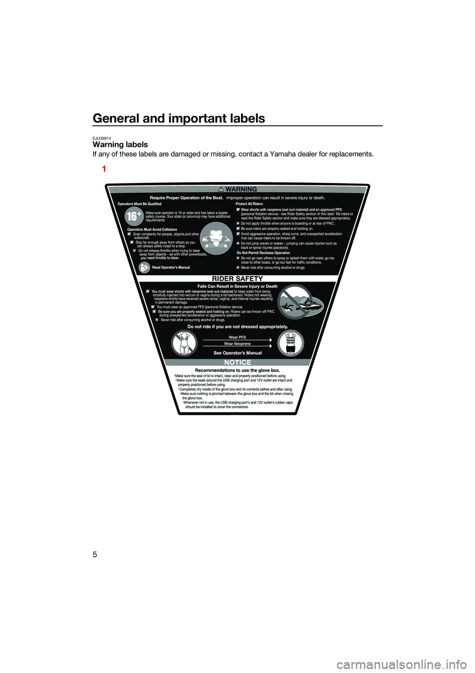
EJU35914Warning labels
If any of these labels are damaged or missing, contact a Yamaha dealer for replacements.
1
UF3V73E0.book Page 5 Friday, October 8, 2021 1:30 PM
Page 36 of 136
Control function operation
27
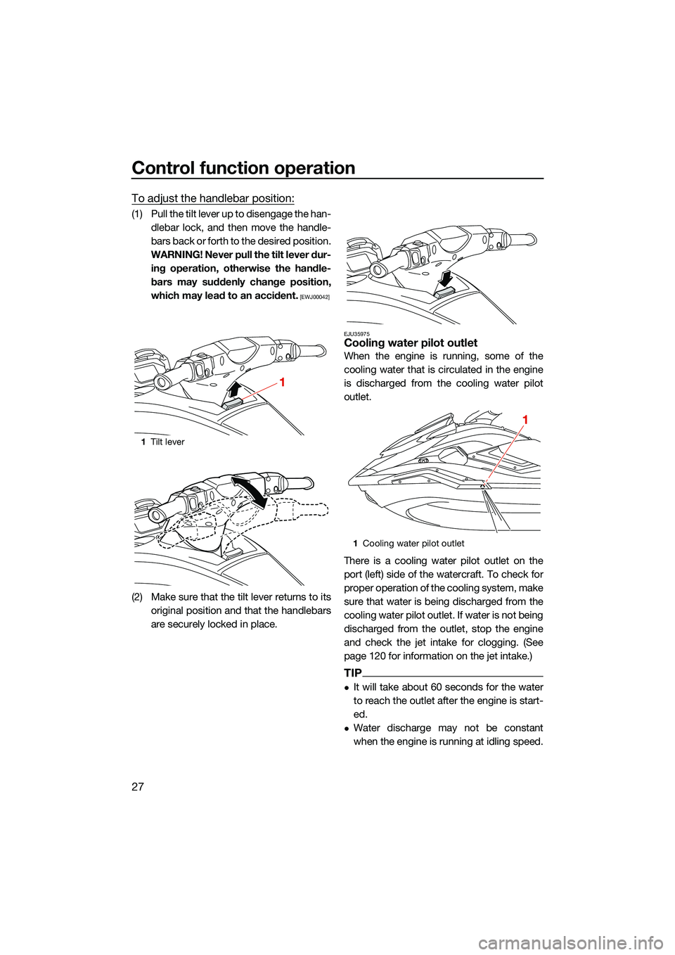
To adjust the handlebar position:
(1) Pull the tilt lever up to disengage the han-dlebar lock, and then move the handle-
bars back or forth to the desired position.
WARNING! Never pull the tilt lever dur- ing operation, otherwise the handle-
bars may suddenly change position,
which may lead to an accident.
[EWJ00042]
(2) Make sure that the tilt lever returns to its original position and that the handlebars
are securely locked in place.
EJU35975Cooling water pilot outlet
When the engine is running, some of the
cooling water that is circulated in the engine
is discharged from the cooling water pilot
outlet.
There is a cooling water pilot outlet on the
port (left) side of the watercraft. To check for
proper operation of the cooling system, make
sure that water is being discharged from the
cooling water pilot outlet. If water is not being
discharged from the outlet, stop the engine
and check the jet intake for clogging. (See
page 120 for information on the jet intake.)
TIP
It will take about 60 seconds for the water
to reach the outlet after the engine is start-
ed.
Water discharge may not be constant
when the engine is running at idling speed.
1Tilt lever
1
1Cooling water pilot outlet
1
UF3V73E0.book Page 27 Friday, October 8, 2021 1:30 PM
Page 51 of 136
Instrument operation
42
EJU46641
Display
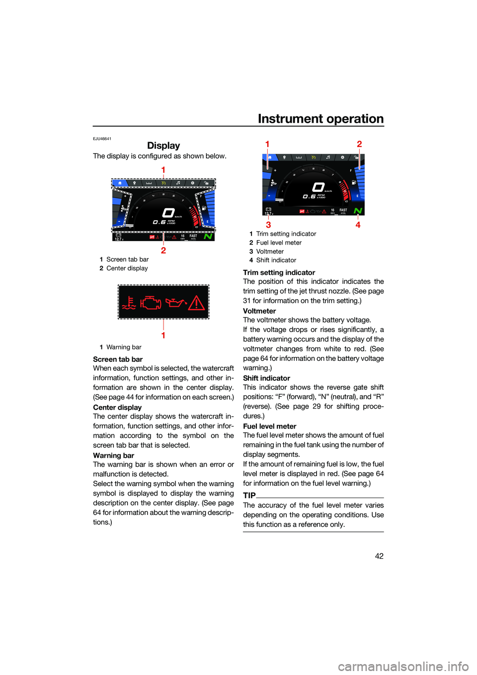
The display is configured as shown below.
Screen tab bar
When each symbol is selected, the watercraft
information, function settings, and other in-
formation are shown in the center display.
(See page 44 for information on each screen.)
Center display
The center display shows the watercraft in-
formation, function settings, and other infor-
mation according to the symbol on the
screen tab bar that is selected.
Warning bar
The warning bar is shown when an error or
malfunction is detected.
Select the warning symbol when the warning
symbol is displayed to display the warning
description on the center display. (See page
64 for information about the warning descrip-
tions.)Trim setting indicator
The position of this indicator indicates the
trim setting of the jet thrust nozzle. (See page
31 for information on the trim setting.)
Voltmeter
The voltmeter shows the battery voltage.
If the voltage drops or rises significantly, a
battery warning occurs and the display of the
voltmeter changes from white to red. (See
page 64 for information on the battery voltage
warning.)
Shift indicator
This indicator shows the reverse gate shift
positions: “F” (forward), “N” (neutral), and “R”
(reverse). (See page 29 for shifting proce-
dures.)
Fuel level meter
The fuel level meter shows the amount of fuel
remaining in the fuel tank using the number of
display segments.
If the amount of remaining fuel is low, the fuel
level meter is displayed in red. (See page 64
for information on the fuel level warning.)
TIP
The accuracy of the fuel level meter varies
depending on the operating conditions. Use
this function as a reference only.
1
Screen tab bar
2 Center display
1 Warning bar
km/h
RPM
x1000
12.7V16KM/HFA S TACCEL
1
2
1
1 Trim setting indicator
2 Fuel level meter
3 Vo l t m et e r
4 Shift indicator
km/h
RPM
x1000
12.7V16KM/HFA S TACCEL
12
34
UF3V73E0.book Page 42 Friday, October 8, 2021 1:30 PM
Page 73 of 136
Instrument operation
64
EJU46930
Warning function
The multifunction information center has the
following warning functions.
Fuel level warning
Battery voltage warning
Check engine warning
Engine overheat warning
Oil pressure warning
Other warnings (communication errors, ex-
ceeding the maintenance intervals, and so
on)
The buzzer that sounds when there is a warn-
ing can be turned off by eliminating the cause
and restarting the engine, or by selecting the
mute button.
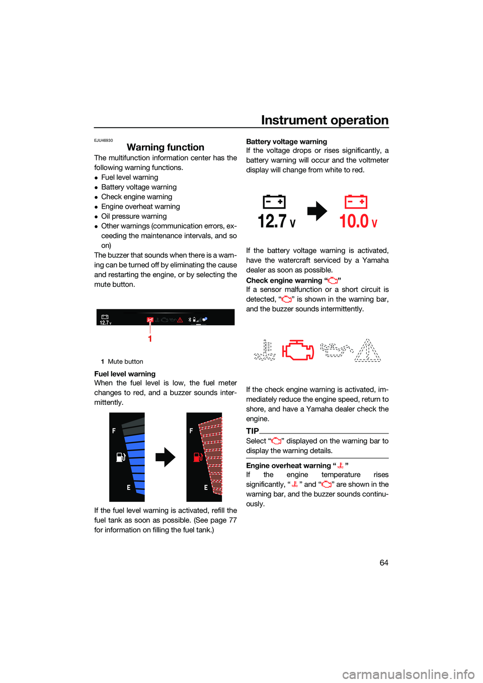
Fuel level warning
When the fuel level is low, the fuel meter
changes to red, and a buzzer sounds inter-
mittently.
If the fuel level warning is activated, refill the
fuel tank as soon as possible. (See page 77
for information on filling the fuel tank.) Battery voltage warning
If the voltage drops or rises significantly, a
battery warning will occur and the voltmeter
display will change from white to red.
If the battery voltage warning is activated,
have the watercraft serviced by a Yamaha
dealer as soon as possible.
Check engine warning “ ”
If a sensor malfunction or a short circuit is
detected, “ ” is shown in the warning bar,
and the buzzer sounds intermittently.
If the check engine warning is activated, im-
mediately reduce the engine speed, return to
shore, and have a Yamaha dealer check the
engine.
TIP
Select “ ” displayed on the warning bar to
display the warning details.
Engine overheat warning “ ”
If the engine temperature rises
significantly, “ ” and “ ” are shown in the
warning bar, and the buzzer sounds continu-
ously.
1
Mute button
12.7V2
1
12.7V10.0V
UF3V73E0.book Page 64 Friday, October 8, 2021 1:30 PM
Page 74 of 136
Instrument operation
65
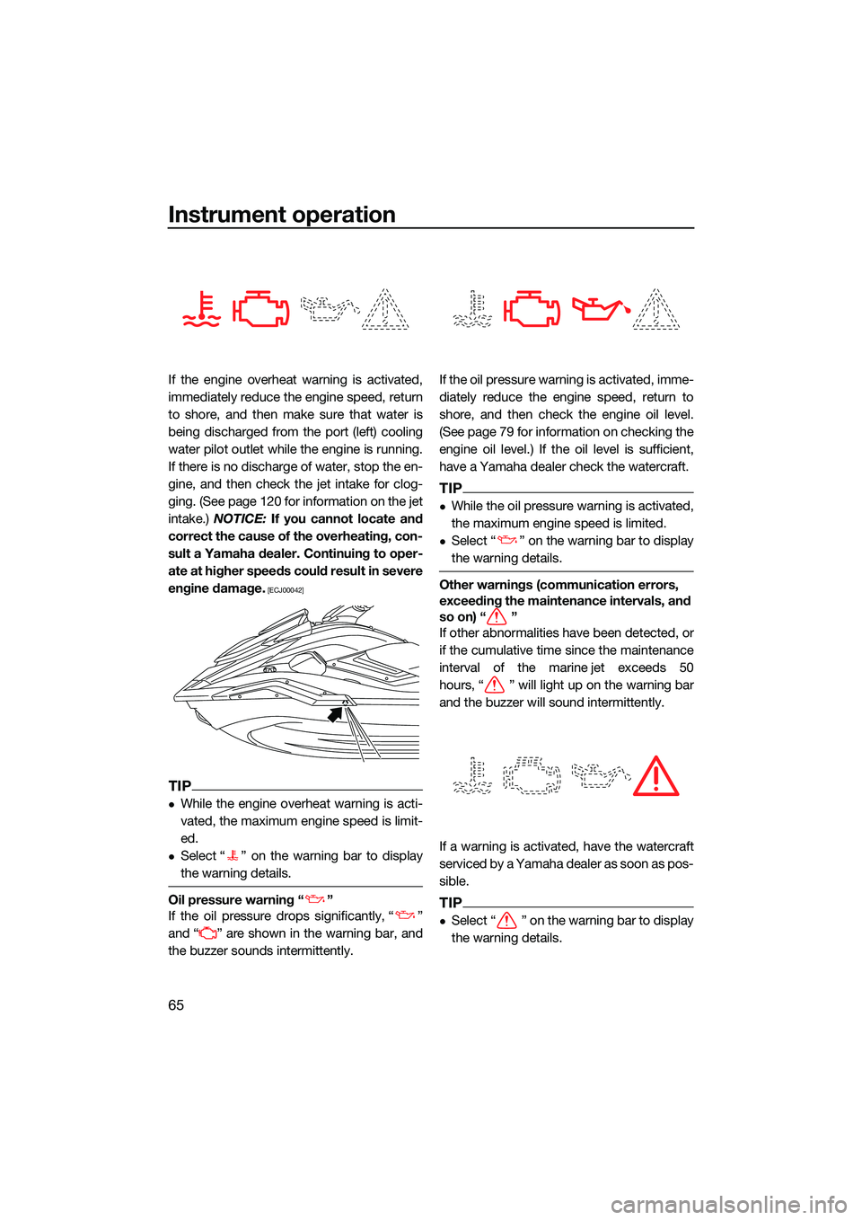
If the engine overheat warning is activated,
immediately reduce the engine speed, return
to shore, and then make sure that water is
being discharged from the port (left) cooling
water pilot outlet while the engine is running.
If there is no discharge of water, stop the en-
gine, and then check the jet intake for clog-
ging. (See page 120 for information on the jet
intake.) NOTICE: If you cannot locate and
correct the cause of the overheating, con-
sult a Yamaha dealer. Continuing to oper-
ate at higher speeds could result in severe
engine damage.
[ECJ00042]
TIP
While the engine overheat warning is acti-
vated, the maximum engine speed is limit-
ed.
Select “ ” on the warning bar to display
the warning details.
Oil pressure warning “ ”
If the oil pressure drops significantly, “ ”
and “ ” are shown in the warning bar, and
the buzzer sounds intermittently. If the oil pressure warning is activated, imme-
diately reduce the engine speed, return to
shore, and then check the engine oil level.
(See page 79 for information on checking the
engine oil level.) If the oil level is sufficient,
have a Yamaha dealer check the watercraft.
TIP
While the oil pressure warning is activated,
the maximum engine speed is limited.
Select “ ” on the warning bar to display
the warning details.
Other warnings (communication errors,
exceeding the maintenance intervals, and
so on) “ ”
If other abnormalities have been detected, or
if the cumulative time since the maintenance
interval of the marine jet exceeds 50
hours, “ ” will light up on the warning bar
and the buzzer will sound intermittently.
If a warning is activated, have the watercraft
serviced by a Yamaha dealer as soon as pos-
sible.
TIP
Select “ ” on the warning bar to display
the warning details.
UF3V73E0.book Page 65 Friday, October 8, 2021 1:30 PM
Page 75 of 136
Instrument operation
66
If the watercraft goes outside the set area
while the “GeoFence” function is activated,
another warning “ ” is displayed.EJU46302
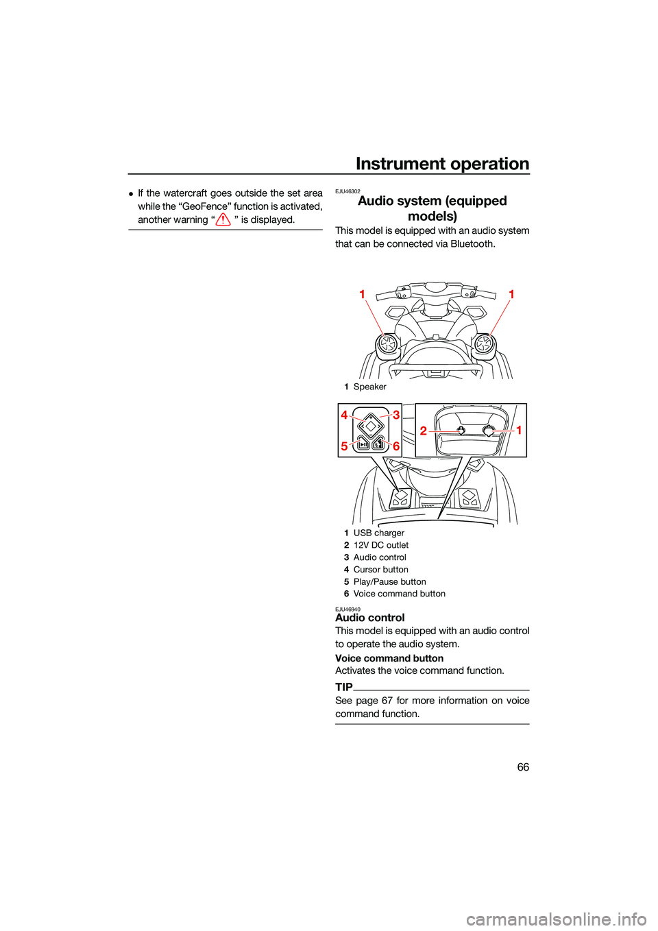
Audio system (equipped models)
This model is equipped with an audio system
that can be connected via Bluetooth.
EJU46940Audio control
This model is equipped with an audio control
to operate the audio system.
Voice command button
Activates the voice command function.
TIP
See page 67 for more information on voice
command function.
1Speaker
1 USB charger
2 12V DC outlet
3 Audio control
4 Cursor button
5 Play/Pause button
6 Voice command button
11
21
4
5
3
6
UF3V73E0.book Page 66 Friday, October 8, 2021 1:30 PM
Page 79 of 136
Equipment operation
70
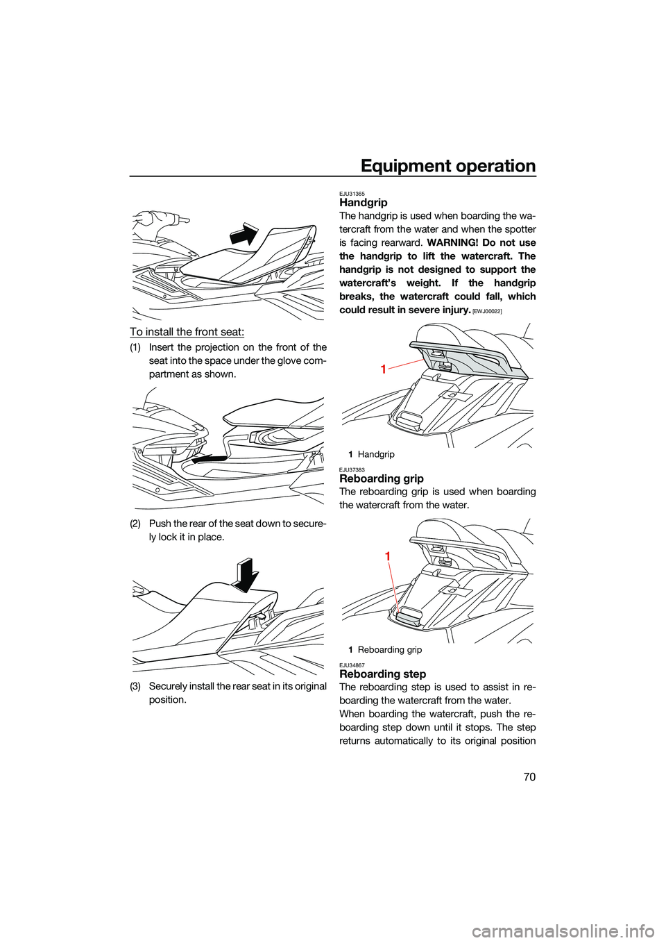
To install the front seat:
(1) Insert the projection on the front of theseat into the space under the glove com-
partment as shown.
(2) Push the rear of the seat down to secure- ly lock it in place.
(3) Securely install the rear seat in its original position.
EJU31365Handgrip
The handgrip is used when boarding the wa-
tercraft from the water and when the spotter
is facing rearward. WARNING! Do not use
the handgrip to lift the watercraft. The
handgrip is not designed to support the
watercraft’s weight. If the handgrip
breaks, the watercraft could fall, which
could result in severe injury.
[EWJ00022]
EJU37383
Reboarding grip
The reboarding grip is used when boarding
the watercraft from the water.
EJU34867Reboarding step
The reboarding step is used to assist in re-
boarding the watercraft from the water.
When boarding the watercraft, push the re-
boarding step down until it stops. The step
returns automatically to its original position
1Handgrip
1 Reboarding grip
1
1
UF3V73E0.book Page 70 Friday, October 8, 2021 1:30 PM