check engine YAMAHA FX SVHO 2022 Owner's Manual
[x] Cancel search | Manufacturer: YAMAHA, Model Year: 2022, Model line: FX SVHO, Model: YAMAHA FX SVHO 2022Pages: 136, PDF Size: 5.75 MB
Page 99 of 136
Pre-operation checks
90
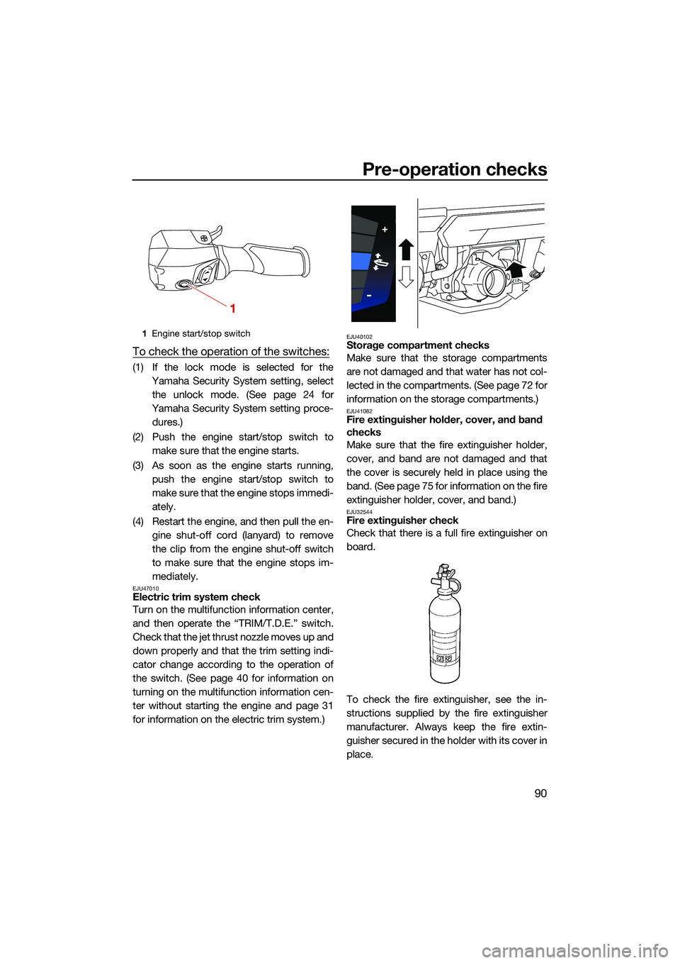
To check the operation of the switches:
(1) If the lock mode is selected for theYamaha Security System setting, selectthe unlock mode. (See page 24 for
Yamaha Security System setting proce- dures.)
(2) Push the engine start/stop switch to make sure that the engine starts.
(3) As soon as the engine starts running, push the engine start/stop switch to
make sure that the engine stops immedi-
ately.
(4) Restart the engine, and then pull the en- gine shut-off cord (lanyard) to remove
the clip from the engine shut-off switch
to make sure that the engine stops im-
mediately.
EJU47010Electric trim system check
Turn on the multifunction information center,
and then operate the “TRIM/T.D.E.” switch.
Check that the jet thrust nozzle moves up and
down properly and that the trim setting indi-
cator change according to the operation of
the switch. (See page 40 for information on
turning on the multifunction information cen-
ter without starting the engine and page 31
for information on the electric trim system.)
EJU40102Storage compartment checks
Make sure that the storage compartments
are not damaged and that water has not col-
lected in the compartments. (See page 72 for
information on the storage compartments.)
EJU41082Fire extinguisher holder, cover, and band
checks
Make sure that the fire extinguisher holder,
cover, and band are not damaged and that
the cover is securely held in place using the
band. (See page 75 for information on the fire
extinguisher holder, cover, and band.)
EJU32544Fire extinguisher check
Check that there is a full fire extinguisher on
board.
To check the fire extinguisher, see the in-
structions supplied by the fire extinguisher
manufacturer. Always keep the fire extin-
guisher secured in the holder with its cover in
place.
1 Engine start/stop switch
1
UF3X73E0.book Page 90 Wednesday, October 6, 2021 9:04 AM
Page 100 of 136
Pre-operation checks
91
Always carry a fire extinguisher on board. A
fire extinguisher is not standard equipment
with this watercraft. If you do not have one,
contact a Yamaha dealer or a fire extinguish-
er dealer to obtain one meeting the proper
specifications.
EJU40122Safety equipment check
Check that safety equipment meeting the ap-
plicable regulations is on board.
EJU32353Hull and deck check
Check the hull and deck for damage or other
problem.
EJU32657Jet intake checks
Make sure that the jet intake is not damaged
or clogged with weeds or debris. If the jet in-
take is clogged, clean it. (See page 120 for in-
formation on the jet intake.)
EJU43221Jet thrust nozzle and reverse gate check
Check the jet thrust nozzle and reverse gate
for damage or other problem.
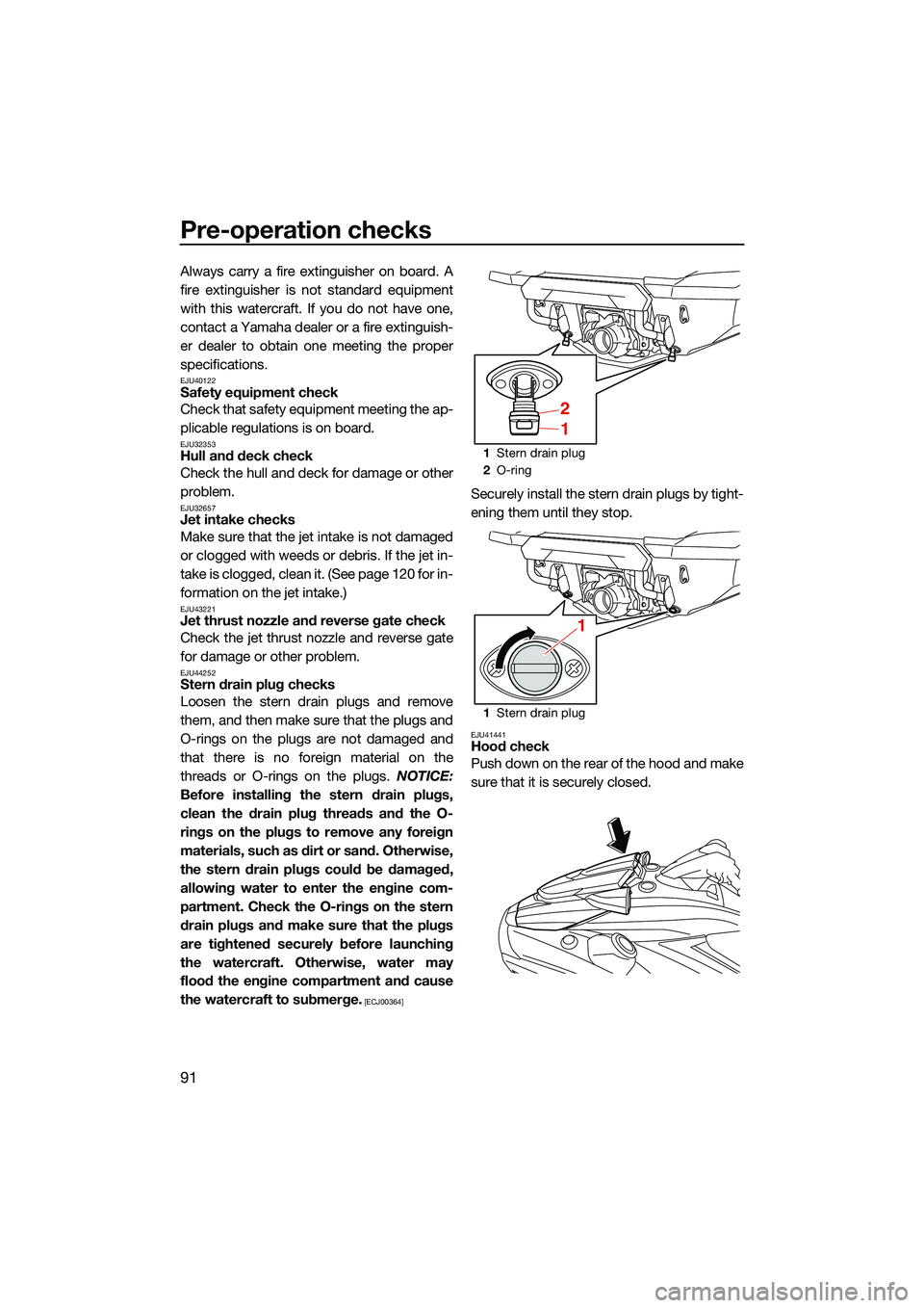
EJU44252Stern drain plug checks
Loosen the stern drain plugs and remove
them, and then make sure that the plugs and
O-rings on the plugs are not damaged and
that there is no foreign material on the
threads or O-rings on the plugs. NOTICE:
Before installing the stern drain plugs,
clean the drain plug threads and the O-
rings on the plugs to remove any foreign
materials, such as dirt or sand. Otherwise,
the stern drain plugs could be damaged,
allowing water to enter the engine com-
partment. Check the O-rings on the stern
drain plugs and make sure that the plugs
are tightened securely before launching
the watercraft. Otherwise, water may
flood the engine compartment and cause
the watercraft to submerge.
[ECJ00364]
Securely install the stern drain plugs by tight-
ening them until they stop.
EJU41441Hood check
Push down on the rear of the hood and make
sure that it is securely closed.
1 Stern drain plug
2 O-ring
1 Stern drain plug
2
1
1
UF3X73E0.book Page 91 Wednesday, October 6, 2021 9:04 AM
Page 101 of 136
Pre-operation checks
92
EJU40147Post-launch checks
Perform the post-launch checks in the pre-
operation checklist while the watercraft is in
the water and the engine is running.
To perform the post-launch checks:
(1) Launch the watercraft. (See page 94 forinformation on launching the watercraft.)
(2) Perform the checks and make sure that there are no malfunctioning items or oth-
er problems.
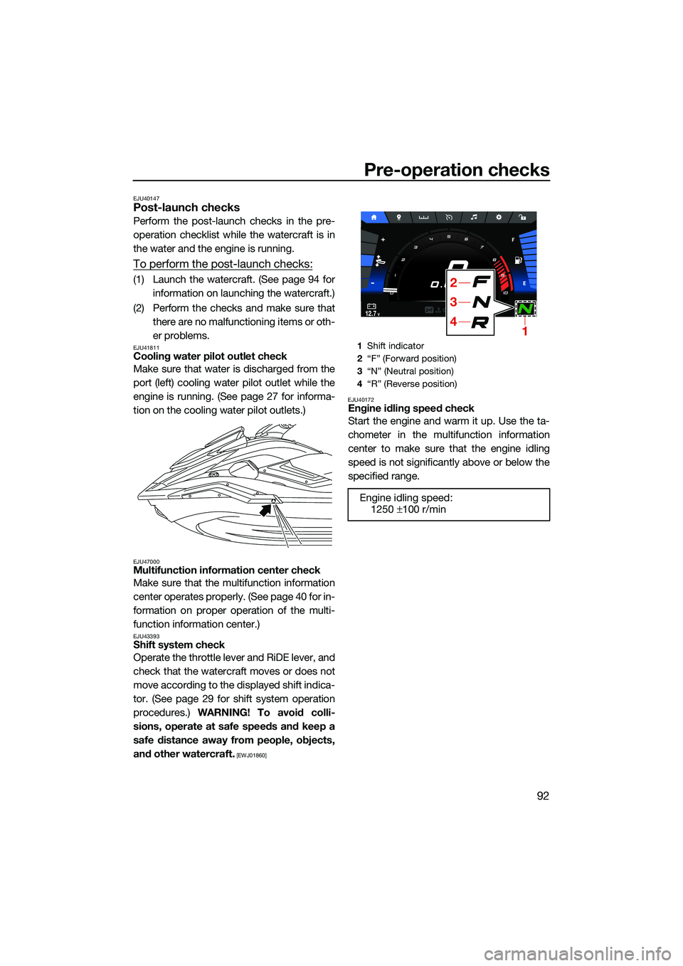
EJU41811Cooling water pilot outlet check
Make sure that water is discharged from the
port (left) cooling water pilot outlet while the
engine is running. (See page 27 for informa-
tion on the cooling water pilot outlets.)
EJU47000Multifunction information center check
Make sure that the multifunction information
center operates properly. (See page 40 for in-
formation on proper operation of the multi-
function information center.)
EJU43393Shift system check
Operate the throttle lever and RiDE lever, and
check that the watercraft moves or does not
move according to the displayed shift indica-
tor. (See page 29 for shift system operation
procedures.) WARNING! To avoid colli-
sions, operate at safe speeds and keep a
safe distance away from people, objects,
and other watercraft.
[EWJ01860] EJU40172
Engine idling speed check
Start the engine and warm it up. Use the ta-
chometer in the multifunction information
center to make sure that the engine idling
speed is not significantly above or below the
specified range.
1
Shift indicator
2 “F” (Forward position)
3 “N” (Neutral position)
4 “R” (Reverse position)
Engine idling speed:
1250 ±100 r/min
MPH
RPM
x1000
12.7V10 :00AM
14
3
2
UF3X73E0.book Page 92 Wednesday, October 6, 2021 9:04 AM
Page 103 of 136
Operation
94
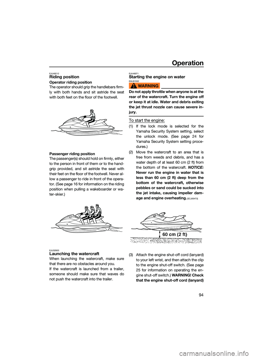
EJU40212Riding position
Operator riding position
The operator should grip the handlebars firm-
ly with both hands and sit astride the seat
with both feet on the floor of the footwell.
Passenger riding position
The passenger(s) should hold on firmly, either
to the person in front of them or to the hand-
grip provided, and sit astride the seat with
their feet on the floor of the footwell. Never al-
low a passenger to ride in front of the opera-
tor. (See page 16 for information on the riding
position when pulling a wakeboarder or wa-
ter-skier.)
EJU32803Launching the watercraft
When launching the watercraft, make sure
that there are no obstacles around you.
If the watercraft is launched from a trailer,
someone should make sure that waves do
not push the watercraft into the trailer.
EJU46071Starting the engine on waterEWJ01532
Do not apply throttle when anyone is at the
rear of the watercraft. Turn the engine off
or keep it at idle. Water and debris exiting
the jet thrust nozzle can cause severe in-
jury.
To start the engine:
(1) If the lock mode is selected for theYamaha Security System setting, selectthe unlock mode. (See page 24 for
Yamaha Security System setting proce- dures.)
(2) Move the watercraft to an area that is free from weeds and debris, and has a
water depth of at least 60 cm (2 ft) from
the bottom of the watercraft. NOTICE:
Never run the engine in water that is
less than 60 cm (2 ft) deep from the
bottom of the watercraft, otherwise
pebbles or sand could be sucked into
the jet intake, causing impeller dam-
age and engine overheating.
[ECJ00473]
(3) Attach the engine shut-off cord (lanyard) to your left wrist, and then attach the clip
to the engine shut-off switch. (See page
25 for information on operating the en-
gine shut-off switch.) WARNING! Check
that the engine shut-off cord (lanyard)
UF3X73E0.book Page 94 Wednesday, October 6, 2021 9:04 AM
Page 107 of 136
Operation
98
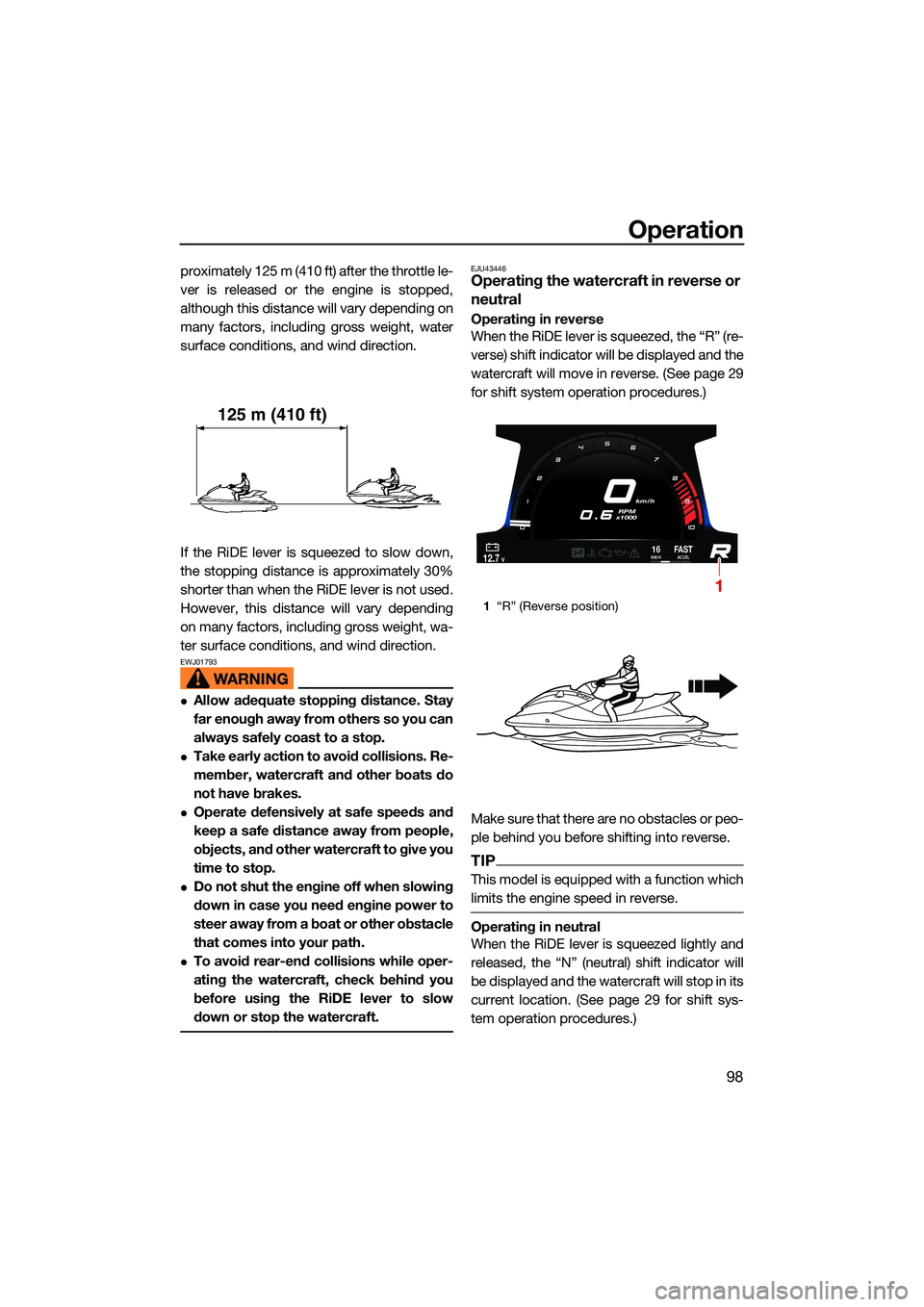
proximately 125 m (410 ft) after the throttle le-
ver is released or the engine is stopped,
although this distance will vary depending on
many factors, including gross weight, water
surface conditions, and wind direction.
If the RiDE lever is squeezed to slow down,
the stopping distance is approximately 30%
shorter than when the RiDE lever is not used.
However, this distance will vary depending
on many factors, including gross weight, wa-
ter surface conditions, and wind direction.
EWJ01793
Allow adequate stopping distance. Stay
far enough away from others so you can
always safely coast to a stop.
Take early action to avoid collisions. Re-
member, watercraft and other boats do
not have brakes.
Operate defensively at safe speeds and
keep a safe distance away from people,
objects, and other watercraft to give you
time to stop.
Do not shut the engine off when slowing
down in case you need engine power to
steer away from a boat or other obstacle
that comes into your path.
To avoid rear-end collisions while oper-
ating the watercraft, check behind you
before using the RiDE lever to slow
down or stop the watercraft.
EJU43446Operating the watercraft in reverse or
neutral
Operating in reverse
When the RiDE lever is squeezed, the “R” (re-
verse) shift indicator will be displayed and the
watercraft will move in reverse. (See page 29
for shift system operation procedures.)
Make sure that there are no obstacles or peo-
ple behind you before shifting into reverse.
TIP
This model is equipped with a function which
limits the engine speed in reverse.
Operating in neutral
When the RiDE lever is squeezed lightly and
released, the “N” (neutral) shift indicator will
be displayed and the watercraft will stop in its
current location. (See page 29 for shift sys-
tem operation procedures.)
125 m (410 ft)
1“R” (Reverse position)
km/h
RPM
x1000
12.7V16KM/HFA S TACCEL
1
UF3X73E0.book Page 98 Wednesday, October 6, 2021 9:04 AM
Page 115 of 136

Care and storage
106
(8) Run the engine at idling speed for about3 minutes watching the engine condition.
If the engine stops while flushing, turn
the water supply off immediately and
perform the procedure again from step 7.
NOTICE: Do not supply water to the
cooling water passages when the en-
gine is not running. The water could
flow back through the muffler into the
engine, causing severe engine dam-
age.
[ECJ00123]
(9) Turn the water supply off.
(10) Discharge the remaining water out of the cooling water passages by alternately
squeezing and releasing the throttle lever
quickly for 10 to 15 seconds.
(11) Stop the engine.
(12) Remove the garden hose adapter, and then securely install the flushing hose
connector cap by tightening it until it
stops.
(13) Securely close the stern storage com- partment.
(14) Securely install the removable watertight storage compartment and seats in their
original positions.
EJU33736Cleaning the watercraft
(1) Remove the seats. (See page 69 for seatremoval and installation procedures.) (2) Rinse the engine and engine compart-
ment with a small amount of water.
NOTICE: Do not use high-pressure
water when rinsing the engine or en-
gine compartment as severe engine
damage could result.
[ECJ00572]
(3) Drain the water from the engine com- partment. (See page 81 for information
on draining the bilge water.)
(4) Wipe the engine and engine compart- ment with a dry cloth.
(5) Wash down the hull, deck, and jet pump with fresh water.
(6) Wipe the hull, deck, and jet pump with a dry cloth.
(7) Wipe all vinyl and rubber components, such as the seats and engine compart-
ment seals, with a vinyl protectant.
(8) To minimize corrosion, spray metallic parts of the hull, deck, and engine with a
rust inhibitor.
(9) Allow the engine compartment to air dry completely before installing the seats.
(10) Securely install the seats in their original positions.
EJU3368DBattery care
If the watercraft will not be used for more than
a month, remove the battery from the water-
craft, check it, and then store it in a cool, dry
place.
EWJ00794
Battery electrolyte is poisonous and dan-
gerous, causing severe burns, etc. Elec-
trolyte contains sulfuric acid. Avoid
contact with skin, eyes, or clothing.
Batteries produce explosive gases. Keep
sparks, flames, cigarettes, etc., well away.
If using or charging the battery in an en-
closed space, make sure that it is well
UF3X73E0.book Page 106 Wednesday, October 6, 2021 9:04 AM
Page 117 of 136
Care and storage
108
(4) Store the battery in a cool, dry place.NOTICE: Storing the battery in an un-
charged condition can cause perma-
nent battery damage. Check the
battery periodically.
[ECJ00103]
To install the battery:
(1) Place the battery in the battery compart- ment and hook the battery bands onto
the holders.
(2) Connect the positive (+) battery lead (red) to the positive (+) battery terminal.
NOTICE: Reversal of the battery leads
will damage the electrical parts.
[ECJ00262]
(3) Connect the negative (–) battery lead (black) to the negative (–) battery termi-
nal.
(4) Make sure that the battery is securely held in place.
EJU33495
Long-term storageEWJ00332
Always place the watercraft upright in a
horizontal position when storing it, other-
wise fuel could leak out into the engine or
engine compartment, which could create
a fire hazard.
Storage for long periods of time, such as win-
ter storage, requires preventive maintenance
to ensure against deterioration. It is advisable
to have the watercraft serviced by a Yamaha
dealer prior to storage.
However, the following procedures can be
performed easily by the owner.
EJU40763Cleaning
(1) Flush the cooling water passages. (Seepage 105 for information on flushing the
cooling water passages.)
TIP
If you will be storing the watercraft for a pro-
longed period, such as winter storage, top off
the fuel tank with fresh gasoline and add fuel
stabilizer and conditioner to the fuel tank ac-
cording to the manufacturer’s instruction be-
fore starting the engine.
(2) Clean the watercraft. (See page 106 forinformation on cleaning the watercraft.)
Wax the hull with a non-abrasive wax.
EJU44741Lubrication
To keep moving parts sliding or rotating
smoothly, lubricate them with water-resistant
grease.
Recommended water-resistant grease:
YAMALUBE MARINE
GREASE/Yamaha Grease A
Recommended water-resistant grease:
YAMALUBE MARINE GREASE /
Ya m a h a G r e a s e A
UF3X73E0.book Page 108 Wednesday, October 6, 2021 9:04 AM
Page 119 of 136
Maintenance
110
EJU3376A
Maintenance
Periodic checks and lubrication will keep
your watercraft in the safest and most effi-
cient condition possible. Therefore, make
sure to carry out the periodic maintenance.
Safety is an obligation of the watercraft own-
er. Proper maintenance must be carried out
to keep the exhaust emission and sound lev-
els within the regulated limits. The most im-
portant points of watercraft inspection and
lubrication are explained on the following pa-
ges.
See a Yamaha dealer for genuine Yamaha re-
placement parts and optional accessories
designed for your watercraft.
Remember, failures that are the result of the
installation of parts or accessories which are
not qualitatively equivalent to genuine
Yamaha parts are not covered by the limited warranty.
Maintenance, replacement, or repair of
the emission control devices and system
may be performed by any marine SI engine
repair establishment or individual. War-
ranty repair, however, must be performed
at an authorized Yamaha marine dealer-
ship.
EWJ00312
Be sure to turn off the engine when you
perform maintenance unless otherwise
specified. If you are not familiar with ma-
chine servicing, this work should be done
by a Yamaha dealer or other qualified me-
chanic.
EJU42023Removing and installing the engine
cover
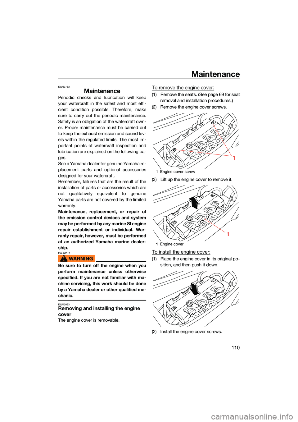
The engine cover is removable.
To remove the engine cover:
(1) Remove the seats. (See page 69 for seat removal and installation procedures.)
(2) Remove the engine cover screws.
(3) Lift up the engine cover to remove it.
To install the engine cover:
(1) Place the engine cover in its original po- sition, and then push it down.
(2) Install the engine cover screws.
1 Engine cover screw
1 Engine cover
1
1
UF3X73E0.book Page 110 Wednesday, October 6, 2021 9:04 AM
Page 121 of 136

Maintenance
112
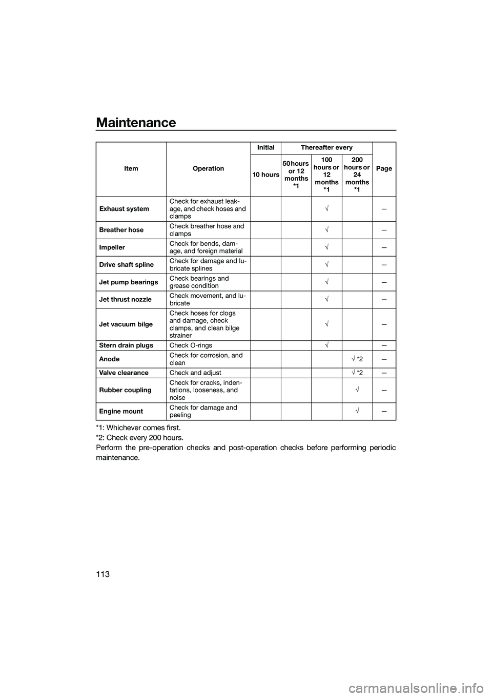
EJU43103Periodic maintenance chart
The periodic maintenance chart gives general guidelines for periodic maintenance. Have a
Yamaha dealer perform the checks in the following chart. However, maintenance may need to be performed more frequently depending on your operating conditions. If you have any
questions, consult a Yamaha dealer.
This “ √” mark indicates items to be checked and serviced by a Yamaha dealer.
Item OperationInitial Thereafter every
Page
10 hours 50 hours
or 12
months *1 100
hours or 12
months *1 200
hours or 24
months *1
Fuel line Check fuel hoses and
clamps
√
—
Fuel filler cap/Wa-
ter separator Check O-rings for cracks
and deformation
√
—
Fuel tank Check installation and
straps
√
—
Water inlet strainer Check for clogs and dam-
age
√
—
Cooling water hos-
es Check for damage and
leakage, and check
clamps
√
—
Engine oil Replace √√ 114
Oil filter Replace √114
Intermediate hous-
ing Lubricate
√—
Spark plugs Check √√ —
Battery Check state of charge,
terminals and bands
√
—
Battery leads Check terminals √—
Steering master Check operation and for
looseness
√√
—
Steering cable Check exterior and con-
nections, and lubricate
√
—
Electric trim rod Check exterior and con-
nections, and lubricate
√
—
Shift rod and re-
verse gate Check exterior and con-
nections, and lubricate
√
—
Air filter element Check for damage and
dirt
√
—
Air intake hoses Check for damage, and
check clamps
√
—
Thr
ottle body Lubricate throttle valve √—
UF3X73E0.book Page 112 Wednesday, October 6, 2021 9:04 AM
Page 122 of 136
Maintenance
113
*1: Whichever comes first.
*2: Check every 200 hours.
Perform the pre-operation checks and post-operation checks before performing periodic
maintenance.
Exhaust systemCheck for exhaust leak-
age, and check hoses and
clamps √
—
Breather hose Check breather hose and
clamps
√
—
Impeller Check for bends, dam-
age, and foreign material
√
—
Drive shaft spline Check for damage and lu-
bricate splines
√
—
Jet pump bearings Check bearings and
grease condition
√
—
Jet thrust nozzle Check movement, and lu-
bricate
√
—
Jet vacuum bilge Check hoses for clogs
and damage, check
clamps, and clean bilge
strainer
√
—
Stern drain plugs Check O-rings √—
Anode Check for corrosion, and
clean
√
*2 —
Valve clearance Check and adjust √ *2 —
Rubber coupling Check for cracks, inden-
tations, looseness, and
noise √
—
Engine mount Check for damage and
peeling
√
—
Item Operation
Initial Thereafter every
Page
10 hours 50 hours
or 12
months *1 100
hours or 12
months *1 200
hours or 24
months *1
UF3X73E0.book Page 113 Wednesday, October 6, 2021 9:04 AM