check oil YAMAHA FZR 2013 Owners Manual
[x] Cancel search | Manufacturer: YAMAHA, Model Year: 2013, Model line: FZR, Model: YAMAHA FZR 2013Pages: 104, PDF Size: 5.07 MB
Page 5 of 104
Table of contents
General and important labels ........... 1Identification numbers .................... 1
Primary Identification (PRI-ID)
number ........................................... 1
Craft Identification Number (CIN) ...... 1
Engine serial number ........................ 1
Manufactured date label .................... 2
Model information ........................... 2
Builder’s plate .................................... 2
Important labels .............................. 4
Warning labels ................................... 5
Other labels ....................................... 9
Safety information ........................... 11 Limitations on who may operate the watercraft ............................ 11
Cruising limitations ....................... 12
Operation requirements ............... 13
Recommended equipment ........... 15
Hazard information ....................... 16
Watercraft characteristics ............. 16
Safe boating rules ........................ 18
Enjoy your watercraft responsibly ................................ 18
Description....................................... 20 Watercraft glossary ...................... 20
Location of main components ...... 21
Control function operation ............. 25 Watercraft control functions ......... 25
Remote control transmitter .............. 25
Yamaha Security System ................ 26
Engine stop switch .......................... 27
Engine shut-off switch ..................... 27
Start switch ...................................... 27
Throttle lever ................................... 28
Steering system ............................... 28
Telescopic steering system ............. 29
Cooling water pilot outlets ............... 29
Water separator ............................... 30
Watercraft operation ....................... 31Watercraft operation functions ..... 31
Reverse system ............................... 31
Quick Shift Trim System
(Q.S.T.S.) ..................................... 32
Watercraft operation modes ......... 33
Low RPM Mode ............................... 33
Instrument operation ...................... 35Dual analog meter unit ................. 35
Speedometer ................................... 35
Tachometer ..................................... 35
Information display .......................... 36
Equipment operation ...................... 40Equipment .................................... 40
Seats ............................................... 40
Reboarding grip ............................... 41
Reboarding step .............................. 41
Bow eye ........................................... 42
Stern eyes ....................................... 42
Storage compartments .................... 42
Fire extinguisher holder and
cover ............................................ 45
Operation and handling
requirements ................................... 47Fuel requirements ........................ 47
Fuel ................................................. 47
Engine oil requirements ............... 49
Engine oil ......................................... 49
Draining the bilge water ............... 50
Draining the bilge water on land ...... 50
Draining the bilge water on water .... 51
Transporting on a trailer ............... 52
First-time operation ........................ 53 Engine break-in ............................ 53
Pre-operation checks ..................... 54
Pre-operation checklist .................... 54
Pre-operation check points .......... 56
Pre-launch checks ........................... 56
UF2R74E0.book Page 1 Wednesday, August 22, 2012 2:26 PM
Page 6 of 104
Table of contents
Post-launch checks ......................... 63
Operation ......................................... 64Operating your watercraft ............. 64
Getting to know your watercraft ....... 64
Learning to operate your
watercraft ..................................... 64
Riding position ................................. 65
Launching the watercraft ................. 65
Starting the engine on water ........... 65
Stopping the engine ........................ 66
Leaving the watercraft ..................... 66
Operating the watercraft .................. 66
Turning the watercraft ..................... 67
Stopping the watercraft ................... 68
Operating the watercraft in reverse ......................................... 69
Boarding the watercraft ................... 69
Starting off ....................................... 72
Capsized watercraft ......................... 73
Beaching and docking the watercraft ..................................... 74
Operating in weeded areas ............. 74
After removing the watercraft from
the water ...................................... 75
Care and storage ............................. 76Post-operation care ...................... 76
Flushing the cooling water
passages ...................................... 76
Cleaning the watercraft ................... 77
Battery care ..................................... 77
Long-term storage ........................ 80
Cleaning .......................................... 80
Lubrication ....................................... 80
Rustproofing .................................... 80
Maintenance..................................... 82 Maintenance ................................. 82
Tool kit ............................................. 82
Removing and installing the engine
cover ............................................ 82
Periodic maintenance chart ............. 84
Engine oil and oil filter ..................... 85
Specifications.................................. 86 Specifications ................................ 86
Trouble recovery ............................. 87 Troubleshooting ........................... 87
Troubleshooting chart ...................... 87
Emergency procedures ................ 90
Cleaning the jet intake and
impeller ........................................ 90
Jumping the battery ......................... 91
Replacing the fuses ......................... 91
Replacing the bilge pump fuse ........ 93
Towing the watercraft ...................... 94
Submerged watercraft ..................... 95
UF2R74E0.book Page 2 Wednesday, August 22, 2012 2:26 PM
Page 42 of 104

Instrument operation
36
EJU35024Information display
The information display shows watercraft op-
erating conditions.
EJU37264Hour meter/voltmeter
The hour meter/voltmeter has both an hour
meter function and a voltmeter function. By
switching the meter, it can be used as either
an hour meter or a voltmeter.
TIP:
The hour meter is selected at the Yamaha
factory.Hour meter
The hour meter shows the total number of
hours that the engine has been running since
the watercraft was new.
TIP:
The elapsed time will be kept even if the bat-
tery terminals have been disconnected.
To switch to the hour meter from the voltme-
ter:
Push the “Hour Volt” button for at least 1 sec-
ond. The display switches to the hour meter
from the voltmeter.
Voltmeter
The voltmeter shows the battery voltage.
When the battery voltage is normal, the volt-
meter displays approximately 12 volts.
If the battery voltage has dropped significant-
ly, “LO” is displayed on the voltmeter. If the
battery voltage has risen significantly, “HI” is
displayed. If “LO” or “HI” is displayed, immedi-
ately return to shore and have a Yamaha
dealer service the watercraft.
1
Fuel level meter
2 Fuel indicator
3 Engine overheat warning indicator
4 Check engine warning indicator
5 Oil pressure warning indicator
6 Hour meter/voltmeter
1 Hour meter/voltmeter
12345
6
1
1 “Hour Volt” button
2 Hour meter
1
2
UF2R74E0.book Page 36 Wednesday, August 22, 2012 2:26 PM
Page 44 of 104

Instrument operation
38
sounds intermittently. At the same time, the
maximum engine speed is limited.
If the oil pressure warning is activated, imme-
diately reduce the engine speed, return to
shore, and then check the engine oil level.
(See page 49 for information on checking the
engine oil level.) If the oil level is sufficient,
have a Yamaha dealer check the watercraft.
TIP:
Push the “Hour Volt” button to stop the buzz-
er.
EJU37303Engine overheat warning
If the engine temperature rises significantly,
the engine overheat warning indicator and the
“WARNING” indicator light blink, and the
buzzer sounds intermittently. Then, the en-
gine overheat warning indicator and the
“WARNING” indicator light stop blinking and
remain on, and the buzzer sounds continu-
ously. At the same time, the maximum engine
speed is limited.If the engine overheat warning is activated,
immediately reduce the engine speed, return
to shore, and then make sure that water is be-
ing discharged from the port (left) cooling wa-
ter pilot outlet while the engine is running. If
there is no discharge of water, stop the en-
gine, and then check the jet intake for clog-
ging. (See page 90 for information on the jet
intake.)
NOTICE: If you cannot locate and
correct the cause of the overheating, con-
sult a Yamaha dealer. Continuing to oper-
ate at higher speeds could result in severe
engine damage.
[ECJ00041]
TIP:
Push the “Hour Volt” button to stop the buzz-
er.
EJU37312Check engine warning
If a sensor malfunction or a short circuit is de-
tected, the check engine warning indicator
and the “WARNING” indicator light blink, and
the buzzer sounds intermittently.
UF2R74E0.book Page 38 Wednesday, August 22, 2012 2:26 PM
Page 55 of 104
Operation and handling requirements
49
EJU40290
Engine oil requirements EJU41510Engine oil
NOTICE
ECJ00281
Use only 4-stroke engine oil. Usage of 2-
stroke engine oil could result in severe en-
gine damage.
Checking the engine oil level
WARNING
EWJ00340
Engine oil is extremely hot immediately af-
ter the engine is turned off. Coming in con-
tact with or getting any engine oil on your
clothes could result in burns.
NOTICE
ECJ01001
Make sure that debris and water do not en-
ter the oil filler hole. Debris and water in
the engine oil can cause serious engine
damage.
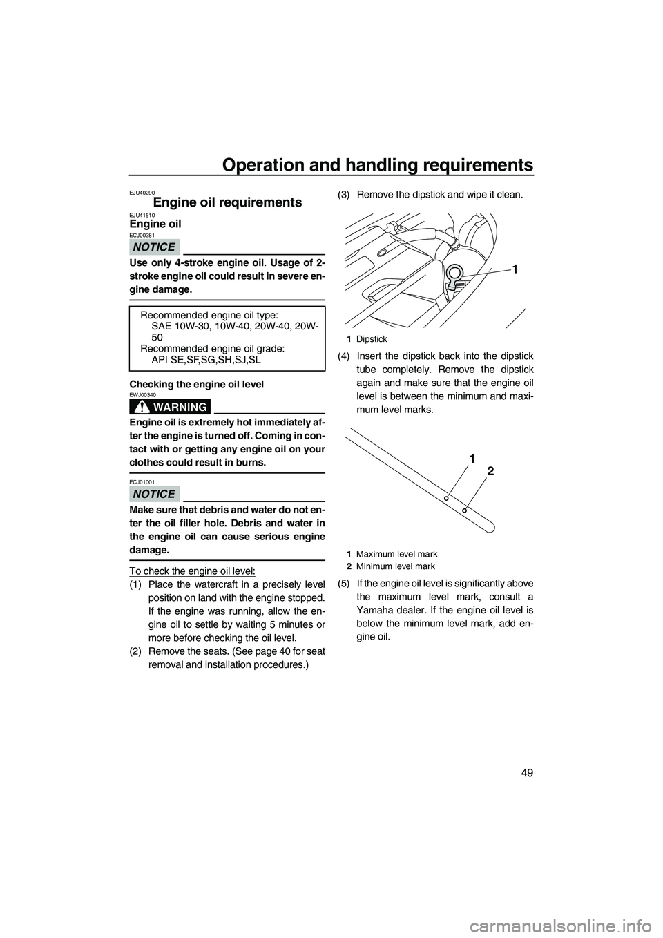
To check the engine oil level:
(1) Place the watercraft in a precisely levelposition on land with the engine stopped.
If the engine was running, allow the en-
gine oil to settle by waiting 5 minutes or
more before checking the oil level.
(2) Remove the seats. (See page 40 for seat removal and installation procedures.) (3) Remove the dipstick and wipe it clean.
(4) Insert the dipstick back into the dipstick
tube completely. Remove the dipstick
again and make sure that the engine oil
level is between the minimum and maxi-
mum level marks.
(5) If the engine oil level is significantly above the maximum level mark, consult a
Yamaha dealer. If the engine oil level is below the minimum level mark, add en-
gine oil.
Recommended engine oil type:
SAE 10W-30, 10W-40, 20W-40, 20W-
50
Recommended engine oil grade: API SE,SF,SG,SH,SJ,SL
1Dipstick
1 Maximum level mark
2 Minimum level mark
1
2
1
UF2R74E0.book Page 49 Wednesday, August 22, 2012 2:26 PM
Page 56 of 104
Operation and handling requirements
50
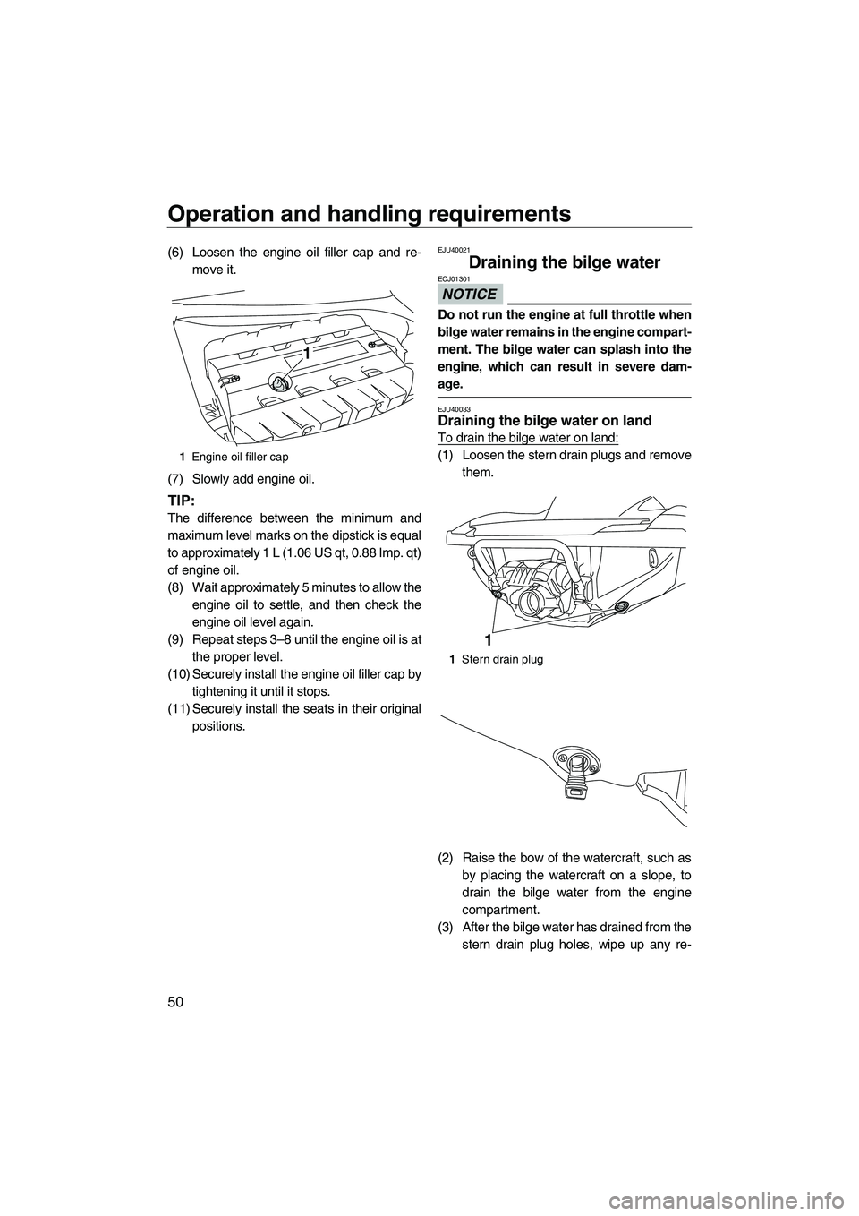
(6) Loosen the engine oil filler cap and re-move it.
(7) Slowly add engine oil.
TIP:
The difference between the minimum and
maximum level marks on the dipstick is equal
to approximately 1 L (1.06 US qt, 0.88 Imp. qt)
of engine oil.
(8) Wait approximately 5 minutes to allow the engine oil to settle, and then check the
engine oil level again.
(9) Repeat steps 3–8 until the engine oil is at the proper level.
(10) Securely install the engine oil filler cap by tightening it until it stops.
(11) Securely install the seats in their original positions.
EJU40021
Draining the bilge water
NOTICE
ECJ01301
Do not run the engine at full throttle when
bilge water remains in the engine compart-
ment. The bilge water can splash into the
engine, which can result in severe dam-
age.
EJU40033Draining the bilge water on land
To drain the bilge water on land:
(1) Loosen the stern drain plugs and removethem.
(2) Raise the bow of the watercraft, such as by placing the watercraft on a slope, to
drain the bilge water from the engine
compartment.
(3) After the bilge water has drained from the stern drain plug holes, wipe up any re-1Engine oil filler cap
1
1Stern drain plug
1
UF2R74E0.book Page 50 Wednesday, August 22, 2012 2:26 PM
Page 59 of 104
First-time operation
53
EJU36665
Engine break-in
NOTICE
ECJ00431
Failure to perform the engine break-in
could result in reduced engine life or even
severe engine damage.
The engine break-in is essential to allow the
various components of the engine to wear
and polish themselves to the correct operat-
ing clearances. This ensures proper perfor-
mance and promotes longer component life.
To perform the engine break-in:
(1) Check the engine oil level. (See page 49for information on checking the engine oil
level.)
(2) Launch the watercraft and start the en- gine. (See page 65 for information on
starting the engine.)
(3) For the first 5 minutes, operate with the engine speed at 2000 r/min.
(4) For the next 30 minutes, operate with the engine speed below 5000 r/min.
(5) For the next 1 hour, operate with the en- gine speed below 6000 r/min.
After the engine break-in is complete, the wa-
tercraft can be operated normally.
UF2R74E0.book Page 53 Wednesday, August 22, 2012 2:26 PM
Page 60 of 104
Pre-operation checks
54
EJU31981
WARNING
EWJ00411
Failure to inspect or maintain the watercraft properly increases the possibility of an ac-
cident or damage to the watercraft. Do not operate the watercraft if you find any prob-
lem. If a problem cannot be corrected by the procedures provided in this manual, have
the watercraft inspected by a Yamaha dealer.
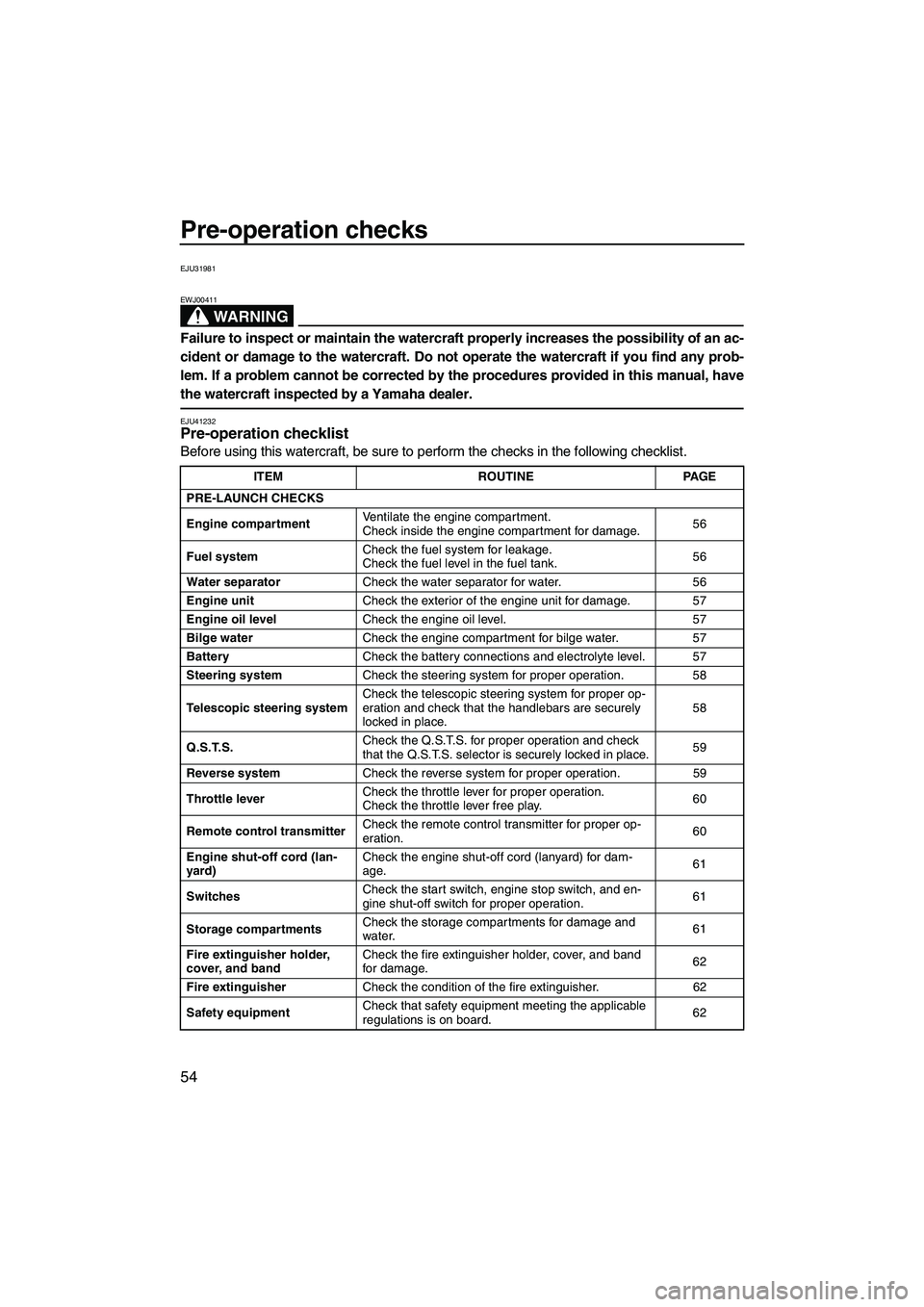
EJU41232Pre-operation checklist
Before using this watercraft, be sure to perform the checks in the following checklist.
ITEM ROUTINEPAGE
PRE-LAUNCH CHECKS
Engine compartment Ventilate the engine compartment.
Check inside the engine compartment for damage.
56
Fuel system Check the fuel system for leakage.
Check the fuel level in the fuel tank.
56
Water separator Check the water separator for water. 56
Engine unit Check the exterior of the engine unit for damage. 57
Engine oil level Check the engine oil level. 57
Bilge water Check the engine compartment for bilge water. 57
Battery Check the battery connections and electrolyte level. 57
Steering system Check the steering system for proper operation. 58
Telescopic steering system Check the telescopic steering system for proper op-
eration and check that the handlebars are securely
locked in place. 58
Q.S.T.S. Check the Q.S.T.S. for proper operation and check
that the Q.S.T.S. selector is securely locked in place.
59
Reverse system Check the reverse system for proper operation. 59
Throttle lever Check the throttle lever for proper operation.
Check the throttle lever free play.
60
Remote control transmitter Check the remote control transmitter for proper op-
eration.
60
Engine shut-off cord (lan-
yard) Check the engine shut-off cord (lanyard) for dam-
age.
61
Switches Check the start switch, engine stop switch, and en-
gine shut-off switch for proper operation.
61
Storage compartments Check the storage compartments for damage and
water.
61
Fire extinguisher holder,
cover, and band Check the fire extinguisher holder, cover, and band
for damage.
62
Fire extinguisher Check the condition of the fire extinguisher. 62
Safety equipment Check that safety equipment meeting the applicable
regulations is on board.
62
UF2R74E0.book Page 54 Wednesday, August 22, 2012 2:26 PM
Page 63 of 104
Pre-operation checks
57
EJU40181Engine unit check
Check the exterior of the engine unit for dam-
age or other problem.
EJU36885Engine oil level check
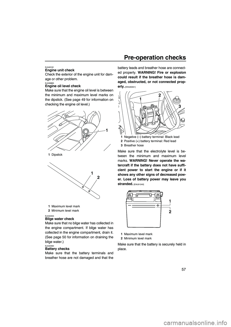
Make sure that the engine oil level is between
the minimum and maximum level marks on
the dipstick. (See page 49 for information on
checking the engine oil level.)
EJU32455Bilge water check
Make sure that no bilge water has collected in
the engine compartment. If bilge water has
collected in the engine compartment, drain it.
(See page 50 for information on draining the
bilge water.)
EJU32484Battery checks
Make sure that the battery terminals and
breather hose are not damaged and that thebattery leads and breather hose are connect-
ed properly.
WARNING! Fire or explosion
could result if the breather hose is dam-
aged, obstructed, or not connected prop-
erly.
[EWJ00451]
Make sure that the electrolyte level is be-
tween the minimum and maximum level
marks. WARNING! Never operate the wa-
tercraft if the battery does not have suffi-
cient power to start the engine or if it
shows any other signs of decreased pow-
er. Loss of battery power may leave you
stranded.
[EWJ01240]
Make sure that the battery is securely held in
place.
1 Dipstick
1 Maximum level mark
2 Minimum level mark
1
2
1
1Negative (–) battery terminal: Black lead
2 Positive (+) battery terminal: Red lead
3 Breather hose
1 Maximum level mark
2 Minimum level mark
12
3
UF2R74E0.book Page 57 Wednesday, August 22, 2012 2:26 PM
Page 83 of 104
Care and storage
77
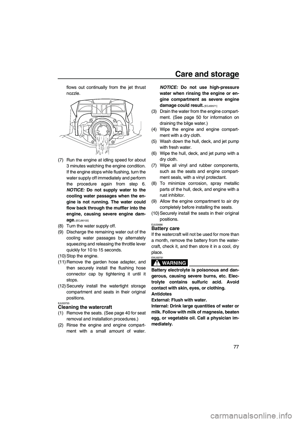
flows out continually from the jet thrust
nozzle.
(7) Run the engine at idling speed for about 3 minutes watching the engine condition.
If the engine stops while flushing, turn the
water supply off immediately and perform
the procedure again from step 6.
NOTICE: Do not supply water to the
cooling water passages when the en-
gine is not running. The water could
flow back through the muffler into the
engine, causing severe engine dam-
age.
[ECJ00122]
(8) Turn the water supply off.
(9) Discharge the remaining water out of the cooling water passages by alternately
squeezing and releasing the throttle lever
quickly for 10 to 15 seconds.
(10) Stop the engine.
(11) Remove the garden hose adapter, and then securely install the flushing hose
connector cap by tightening it until it
stops.
(12) Securely install the watertight storage compartment and seats in their original
positions.
EJU33735Cleaning the watercraft
(1) Remove the seats. (See page 40 for seatremoval and installation procedures.)
(2) Rinse the engine and engine compart- ment with a small amount of water. NOTICE:
Do not use high-pressure
water when rinsing the engine or en-
gine compartment as severe engine
damage could result.
[ECJ00571]
(3) Drain the water from the engine compart- ment. (See page 50 for information on
draining the bilge water.)
(4) Wipe the engine and engine compart- ment with a dry cloth.
(5) Wash down the hull, deck, and jet pump with fresh water.
(6) Wipe the hull, deck, and jet pump with a dry cloth.
(7) Wipe all vinyl and rubber components, such as the seats and engine compart-
ment seals, with a vinyl protectant.
(8) To minimize corrosion, spray metallic parts of the hull, deck, and engine with a
rust inhibitor.
(9) Allow the engine compartment to air dry completely before installing the seats.
(10) Securely install the seats in their original positions.
EJU33686Battery care
If the watercraft will not be used for more than
a month, remove the battery from the water-
craft, check it, and then store it in a cool, dry
place.
WARNING
EWJ00791
Battery electrolyte is poisonous and dan-
gerous, causing severe burns, etc. Elec-
trolyte contains sulfuric acid. Avoid
contact with skin, eyes, or clothing.
Antidotes
External: Flush with water.
Internal: Drink large quantities of water or
milk. Follow with milk of magnesia, beaten
egg, or vegetable oil. Call a physician im-
mediately.
UF2R74E0.book Page 77 Wednesday, August 22, 2012 2:26 PM