YAMAHA GRIZZLY 125 2009 Owners Manual
GRIZZLY 125 2009
YAMAHA
YAMAHA
https://www.carmanualsonline.info/img/51/50336/w960_50336-0.png
YAMAHA GRIZZLY 125 2009 Owners Manual
Trending: headlights, steering wheel, service interval, battery location, tires, compression ratio, bulb
Page 91 of 130
8-23
1
2
3
4
5
6
78
9
10
11
TIP
The engine is warm when it quickly responds to the
throttle.
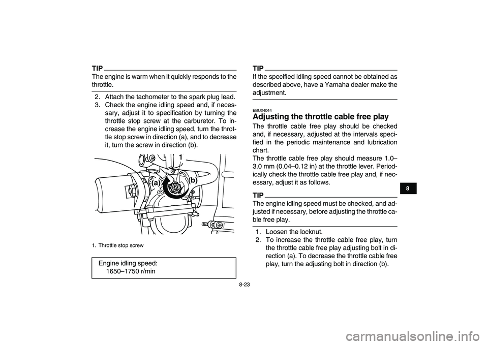
2. Attach the tachometer to the spark plug lead.
3. Check the engine idling speed and, if neces-
sary, adjust it to specification by turning the
throttle stop screw at the carburetor. To in-
crease the engine idling speed, turn the throt-
tle stop screw in direction (a), and to decrease
it, turn the screw in direction (b).TIP
If the specified idling speed cannot be obtained as
described above, have a Yamaha dealer make the
adjustment.
EBU24044
Adjusting the throttle cable free play
The throttle cable free play should be checked
and, if necessary, adjusted at the intervals speci-
fied in the periodic maintenance and lubrication
chart.
The throttle cable free play should measure 1.0–
3.0 mm (0.04–0.12 in) at the throttle lever. Period-
ically check the throttle cable free play and, if nec-
essary, adjust it as follows.TIP
The engine idling speed must be checked, and ad-
justed if necessary, before adjusting the throttle ca-
ble free play.
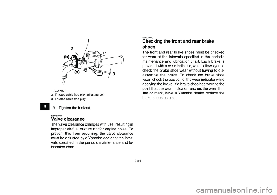
1. Loosen the locknut.
2. To increase the throttle cable free play, turn
the throttle cable free play adjusting bolt in di-
rection (a). To decrease the throttle cable free
play, turn the adjusting bolt in direction (b).
1. Throttle stop screw
Engine idling speed:
1650–1750 r/min
(a)(b) 1
Page 92 of 130
8-24
1
2
3
4
5
6
78
9
10
11
3. Tighten the locknut.
EBU24060
Valve clearance
The valve clearance changes with use, resulting in
improper air-fuel mixture and/or engine noise. To
prevent this from occurring, the valve clearance
must be adjusted by a Yamaha dealer at the inter-
vals specified in the periodic maintenance and lu-
brication chart.
EBU24090
Checking the front and rear brake
shoes
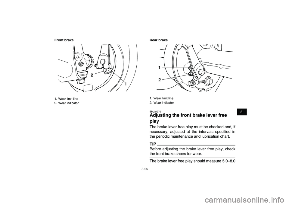
The front and rear brake shoes must be checked
for wear at the intervals specified in the periodic
maintenance and lubrication chart. Each brake is
provided with a wear indicator, which allows you to
check the brake shoe wear without having to dis-
assemble the brake. To check the brake shoe
wear, check the position of the wear indicator while
applying the brake. If a brake shoe has worn to the
point that the wear indicator reaches the wear limit
line or mark, have a Yamaha dealer replace the
brake shoes as a set.
1. Locknut
2. Throttle cable free play adjusting bolt
3. Throttle cable free play
3 1
2
(a) (b)
Page 93 of 130
8-25
1
2
3
4
5
6
78
9
10
11
Front brake Rear brake
EBU24370
Adjusting the front brake lever free
play
The brake lever free play must be checked and, if
necessary, adjusted at the intervals specified in
the periodic maintenance and lubrication chart.TIP
Before adjusting the brake lever free play, check
the front brake shoes for wear.
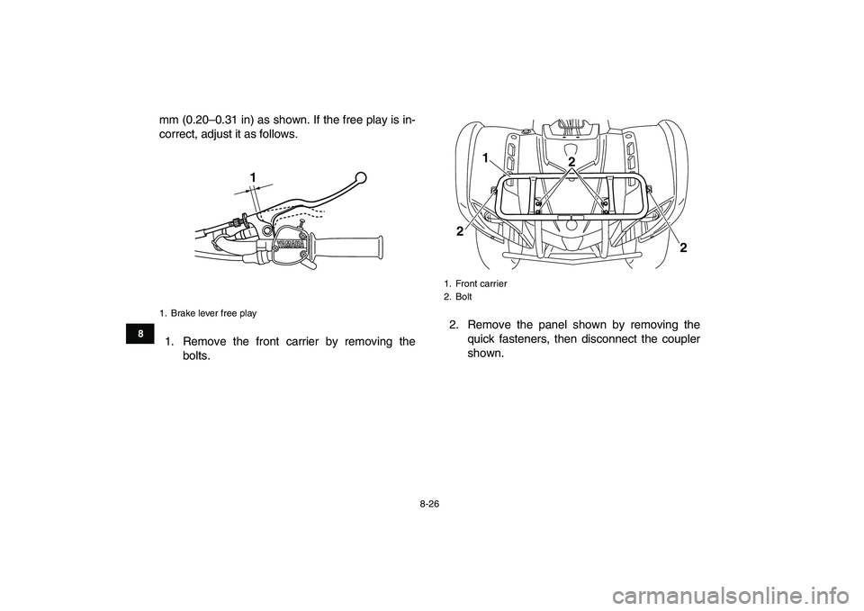
The brake lever free play should measure 5.0–8.0
1. Wear limit line
2. Wear indicator
1 2
1. Wear limit line
2. Wear indicator
1
2
Page 94 of 130
8-26
1
2
3
4
5
6
78
9
10
11
mm (0.20–0.31 in) as shown. If the free play is in-
correct, adjust it as follows.
1. Remove the front carrier by removing the
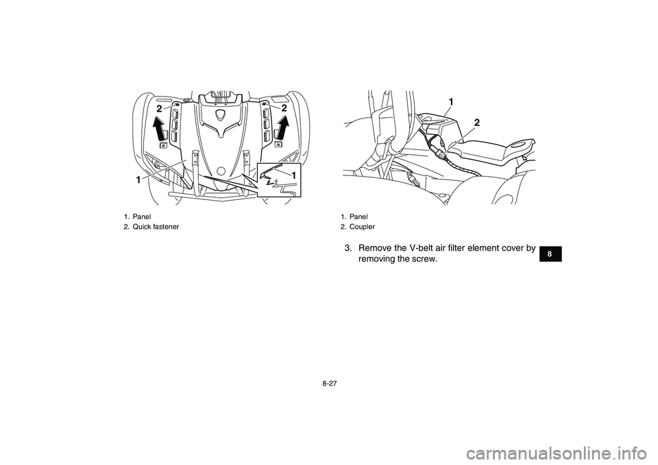
bolts.2. Remove the panel shown by removing the
quick fasteners, then disconnect the coupler
shown.
1. Brake lever free play
1
1. Front carrier
2. Bolt
1
22
2
Page 95 of 130
8-27
1
2
3
4
5
6
78
9
10
11
3. Remove the V-belt air filter element cover by
removing the screw.
1. Panel
2. Quick fastener
122
1
1. Panel
2. Coupler
1
2
Page 96 of 130
8-28
1
2
3
4
5
6
78
9
10
11
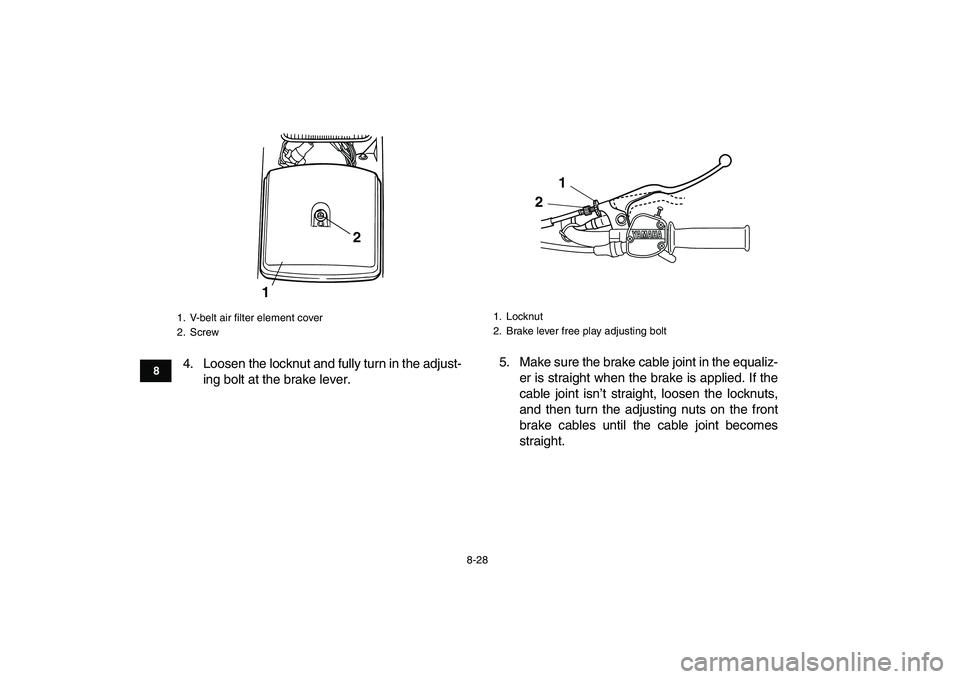
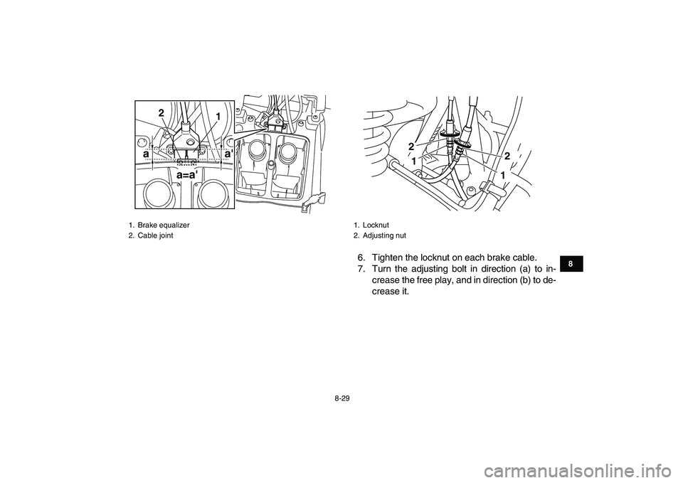
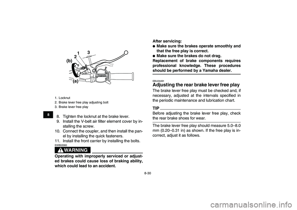
4. Loosen the locknut and fully turn in the adjust-
ing bolt at the brake lever.5. Make sure the brake cable joint in the equaliz-
er is straight when the brake is applied. If the
cable joint isn’t straight, loosen the locknuts,
and then turn the adjusting nuts on the front
brake cables until the cable joint becomes
straight.
1. V-belt air filter element cover
2. Screw
12
1. Locknut
2. Brake lever free play adjusting bolt
1
2
Page 97 of 130
8-29
1
2
3
4
5
6
78
9
10
11
6. Tighten the locknut on each brake cable.
7. Turn the adjusting bolt in direction (a) to in-
crease the free play, and in direction (b) to de-
crease it.
1. Brake equalizer
2. Cable joint
aa'
a=a'
1 2
1. Locknut
2. Adjusting nut
12 2
1
Page 98 of 130
8-30
1
2
3
4
5
6
78
9
10
11
8. Tighten the locknut at the brake lever.
9. Install the V-belt air filter element cover by in-
stalling the screw.
10. Connect the coupler, and then install the pan-
el by installing the quick fasteners.
11. Install the front carrier by installing the bolts.
WARNING
EWB02080
Operating with improperly serviced or adjust-
ed brakes could cause loss of braking ability,
which could lead to an accident.After servicing:
�
Make sure the brakes operate smoothly and
that the free play is correct.
�
Make sure the brakes do not drag.
Replacement of brake components requires
professional knowledge. These procedures
should be performed by a Yamaha dealer.
EBU24491
Adjusting the rear brake lever free play
The brake lever free play must be checked and, if
necessary, adjusted at the intervals specified in
the periodic maintenance and lubrication chart.
TIP
Before adjusting the brake lever free play, check
the rear brake shoes for wear.
The brake lever free play should measure 5.0–8.0
mm (0.20–0.31 in) as shown. If the free play is in-
correct, adjust it as follows.
1. Locknut
2. Brake lever free play adjusting bolt
3. Brake lever free play
3
1
2
(b)
(a)
Page 99 of 130
8-31
1
2
3
4
5
6
78
9
10
11
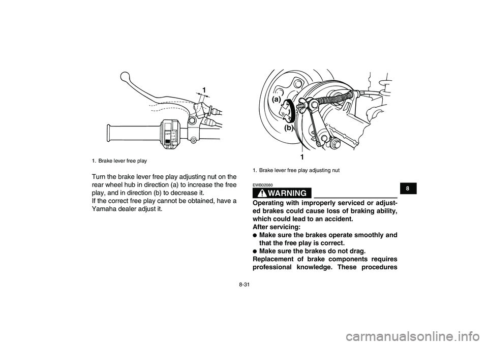
Turn the brake lever free play adjusting nut on the
rear wheel hub in direction (a) to increase the free
play, and in direction (b) to decrease it.
If the correct free play cannot be obtained, have a
Yamaha dealer adjust it.
WARNING
EWB02080
Operating with improperly serviced or adjust-
ed brakes could cause loss of braking ability,
which could lead to an accident.
After servicing:
�
Make sure the brakes operate smoothly and
that the free play is correct.
�
Make sure the brakes do not drag.
Replacement of brake components requires
professional knowledge. These procedures
1. Brake lever free play
1
1. Brake lever free play adjusting nut
1
(a)
(b)
Page 100 of 130
8-32
1
2
3
4
5
6
78
9
10
11
should be performed by a Yamaha dealer.
EBU24872
Drive chain slack
The drive chain slack should be checked before
each ride and adjusted if necessary.
To check the drive chain slack
1. Place the ATV on a level surface.
TIP
When checking and adjusting the drive chain
slack, there should be no weight on the ATV and
all tires must be touching the ground.
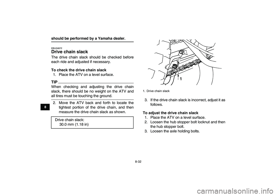
2. Move the ATV back and forth to locate the
tightest portion of the drive chain, and then
measure the drive chain slack as shown.3. If the drive chain slack is incorrect, adjust it as
follows.
To adjust the drive chain slack
1. Place the ATV on a level surface.
2. Loosen the hub stopper bolt locknut and then
the hub stopper bolt.
3. Loosen the axle holding bolts. Drive chain slack:
30.0 mm (1.18 in)
1. Drive chain slack
1
Trending: brake light, checking oil, traction control, load capacity, length, brakes, wheel bolts


