lock YAMAHA GRIZZLY 450 2013 Owner's Manual
[x] Cancel search | Manufacturer: YAMAHA, Model Year: 2013, Model line: GRIZZLY 450, Model: YAMAHA GRIZZLY 450 2013Pages: 172, PDF Size: 3.96 MB
Page 124 of 172
8-32
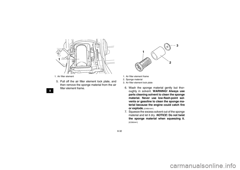
85. Pull off the air filter element lock plate, and
then remove the sponge material from the air
filter element frame. 6. Wash the sponge material gently but thor-
oughly in solvent. WARNING! Always use
parts cleaning solvent to clean the sponge
material. Never use low-flash-point sol-
vents or gasoline to clean the sponge ma-
terial because the engine could catch fire
or explode.
[EWB01941]
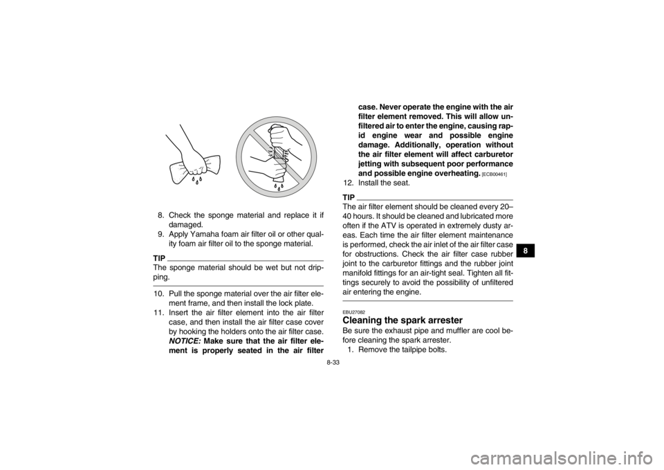
7. Squeeze the excess solvent out of the sponge material and let it dry. NOTICE: Do not twist
the sponge material when squeezing it.
[ECB00441]
1. Air filter element
1. Air filter element frame
2. Sponge material
3. Air filter element lock plate
U1CT62E0.book Page 32 Friday, May 11, 2012 9:03 AM
Page 125 of 172
8-33
8
8. Check the sponge material and replace it if
damaged.
9. Apply Yamaha foam air filter oil or other qual- ity foam air filter oil to the sponge material.
TIPThe sponge material should be wet but not drip-
ping.10. Pull the sponge material over the air filter ele- ment frame, and then install the lock plate.
11. Insert the air filter element into the air filter case, and then install the air filter case cover
by hooking the holders onto the air filter case.
NOTICE: Make sure that the air filter ele-
ment is properly seated in the air filter case. Never operate the engine with the air
filter element removed. This will allow un-
filtered air to enter the engine, causing rap-
id engine wear and possible engine
damage. Additionally, operation without
the air filter element will affect carburetor
jetting with subsequent poor performance
and possible engine overheating.
[ECB00461]
12. Install the seat.TIPThe air filter element should be cleaned every 20–
40 hours. It should be cleaned and lubricated more
often if the ATV is operated in extremely dusty ar-
eas. Each time the air filter element maintenance
is performed, check the air inlet of the air filter case
for obstructions. Check the air filter case rubber
joint to the carburetor fittings and the rubber joint
manifold fittings for an air-tight seal. Tighten all fit-
tings securely to avoid the possibility of unfiltered
air entering the engine.EBU27082Cleaning the spark arrester Be sure the exhaust pipe and muffler are cool be-
fore cleaning the spark arrester.
1. Remove the tailpipe bolts.
U1CT62E0.book Page 33 Friday, May 11, 2012 9:03 AM
Page 129 of 172
8-37
8
TIPIf the specified idling speed cannot be obtained as
described above, have a Yamaha dealer make the
adjustment.5. Install the panel.
EBU24047Adjusting the throttle lever free play The throttle lever free play should be checked and,
if necessary, adjusted at the intervals specified in
the periodic maintenance and lubrication chart.
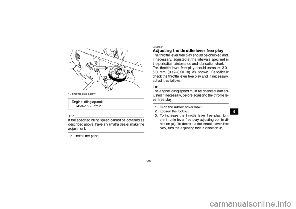
The throttle lever free play should measure 3.0–
5.0 mm (0.12–0.20 in) as shown. Periodically
check the throttle lever free play and, if necessary,
adjust it as follows.TIPThe engine idling speed must be checked, and ad-
justed if necessary, before adjusting the throttle le-
ver free play.1. Slide the rubber cover back.
2. Loosen the locknut.
3. To increase the throttle lever free play, turnthe throttle lever free play adjusting bolt in di-
rection (a). To decrease the throttle lever free
play, turn the adjusting bolt in direction (b).
1. Throttle stop screwEngine idling speed:1450–1550 r/min
U1CT62E0.book Page 37 Friday, May 11, 2012 9:03 AM
Page 130 of 172
8-38
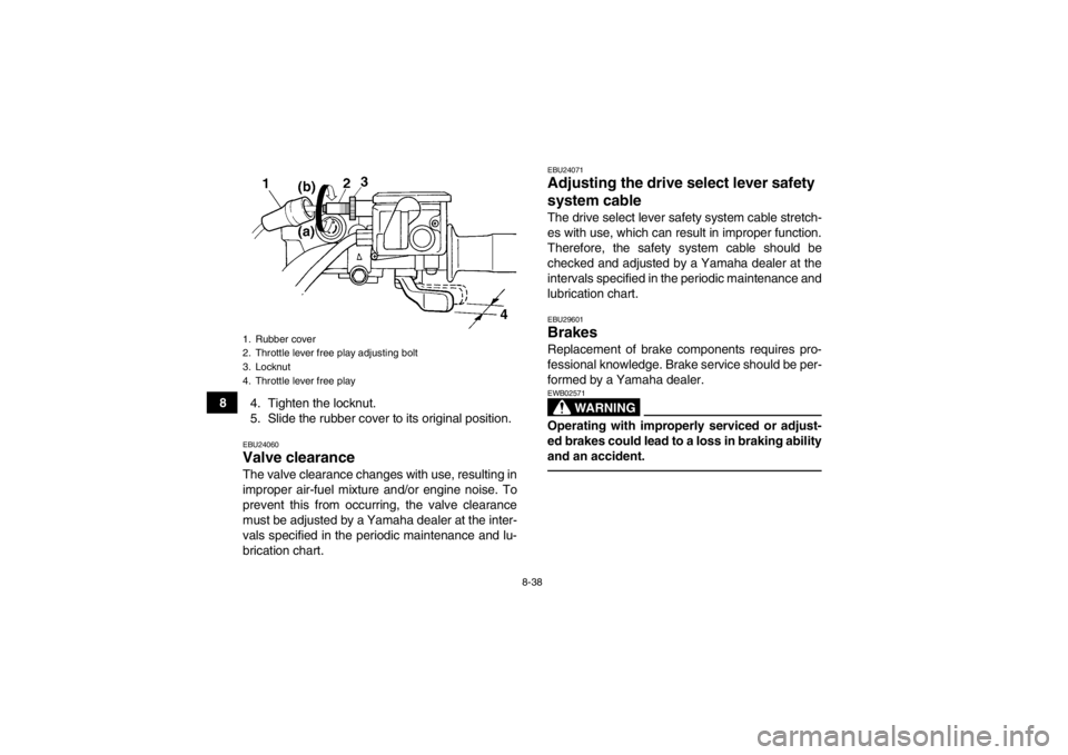
84. Tighten the locknut.
5. Slide the rubber cover to its original position.
EBU24060Valve clearance The valve clearance changes with use, resulting in
improper air-fuel mixture and/or engine noise. To
prevent this from occurring, the valve clearance
must be adjusted by a Yamaha dealer at the inter-
vals specified in the periodic maintenance and lu-
brication chart.
EBU24071Adjusting the drive select lever safety
system cable The drive select lever safety system cable stretch-
es with use, which can result in improper function.
Therefore, the safety system cable should be
checked and adjusted by a Yamaha dealer at the
intervals specified in the periodic maintenance and
lubrication chart.EBU29601Brakes Replacement of brake components requires pro-
fessional knowledge. Brake service should be per-
formed by a Yamaha dealer.
WARNING
EWB02571Operating with improperly serviced or adjust-
ed brakes could lead to a loss in braking ability
and an accident.
1. Rubber cover
2. Throttle lever free play adjusting bolt
3. Locknut
4. Throttle lever free playU1CT62E0.book Page 38 Friday, May 11, 2012 9:03 AM
Page 132 of 172
8-40
8
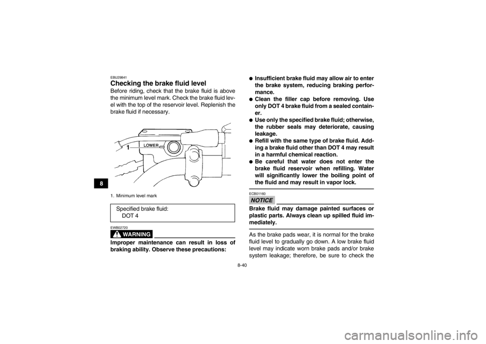
EBU29841Checking the brake fluid level Before riding, check that the brake fluid is above
the minimum level mark. Check the brake fluid lev-
el with the top of the reservoir level. Replenish the
brake fluid if necessary.
WARNING
EWB02720Improper maintenance can result in loss of
braking ability. Observe these precautions:
●Insufficient brake fluid may allow air to enter
the brake system, reducing braking perfor-
mance.●Clean the filler cap before removing. Use
only DOT 4 brake fluid from a sealed contain-
er.●Use only the specified brake fluid; otherwise,
the rubber seals may deteriorate, causing
leakage.●Refill with the same type of brake fluid. Add-
ing a brake fluid other than DOT 4 may result
in a harmful chemical reaction.●Be careful that water does not enter the
brake fluid reservoir when refilling. Water
will significantly lower the boiling point of
the fluid and may result in vapor lock.NOTICEECB01160Brake fluid may damage painted surfaces or
plastic parts. Always clean up spilled fluid im-
mediately.As the brake pads wear, it is normal for the brake
fluid level to gradually go down. A low brake fluid
level may indicate worn brake pads and/or brake
system leakage; therefore, be sure to check the
1. Minimum level markSpecified brake fluid:DOT 4
1
U1CT62E0.book Page 40 Friday, May 11, 2012 9:03 AM
Page 134 of 172
8-42
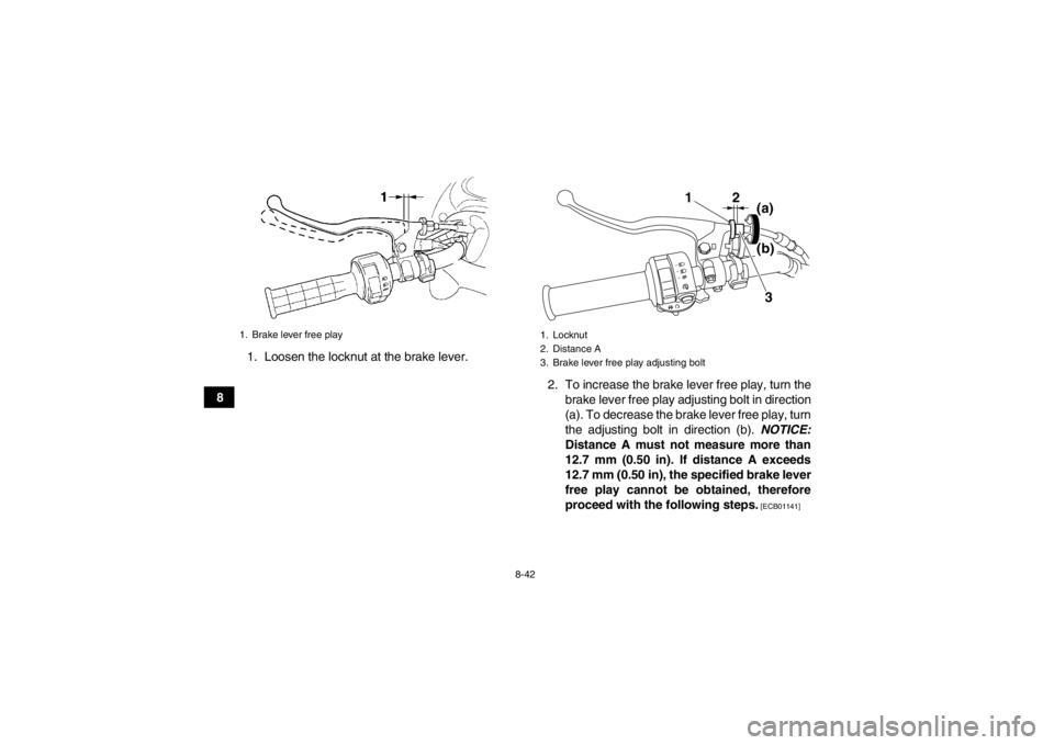
81. Loosen the locknut at the brake lever.
2. To increase the brake lever free play, turn thebrake lever free play adjusting bolt in direction
(a). To decrease the brake lever free play, turn
the adjusting bolt in direction (b). NOTICE:
Distance A must not measure more than
12.7 mm (0.50 in). If distance A exceeds
12.7 mm (0.50 in), the specified brake lever
free play cannot be obtained, therefore
proceed with the following steps.
[ECB01141]
1. Brake lever free play
1. Locknut
2. Distance A
3. Brake lever free play adjusting bolt
12
3
(a)
(b)
U1CT62E0.book Page 42 Friday, May 11, 2012 9:03 AM
Page 135 of 172
8-43
8
TIPIf the specified brake lever free play could be ob-
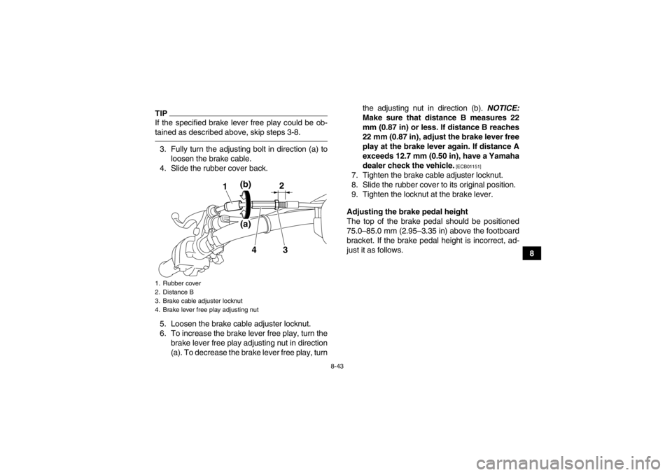
tained as described above, skip steps 3-8.3. Fully turn the adjusting bolt in direction (a) toloosen the brake cable.
4. Slide the rubber cover back.
5. Loosen the brake cable adjuster locknut.
6. To increase the brake lever free play, turn the brake lever free play adjusting nut in direction
(a). To decrease the brake lever free play, turn the adjusting nut in direction (b).
NOTICE:
Make sure that distance B measures 22
mm (0.87 in) or less. If distance B reaches
22 mm (0.87 in), adjust the brake lever free
play at the brake lever again. If distance A
exceeds 12.7 mm (0.50 in), have a Yamaha
dealer check the vehicle.
[ECB01151]
7. Tighten the brake cable adjuster locknut.
8. Slide the rubber cover to its original position.
9. Tighten the locknut at the brake lever.
Adjusting the brake pedal height
The top of the brake pedal should be positioned
75.0–85.0 mm (2.95–3.35 in) above the footboard
bracket. If the brake pedal height is incorrect, ad-
just it as follows.
1. Rubber cover
2. Distance B
3. Brake cable adjuster locknut
4. Brake lever free play adjusting nut
1
2
3
4
(b)(a)
U1CT62E0.book Page 43 Friday, May 11, 2012 9:03 AM
Page 136 of 172
8-44
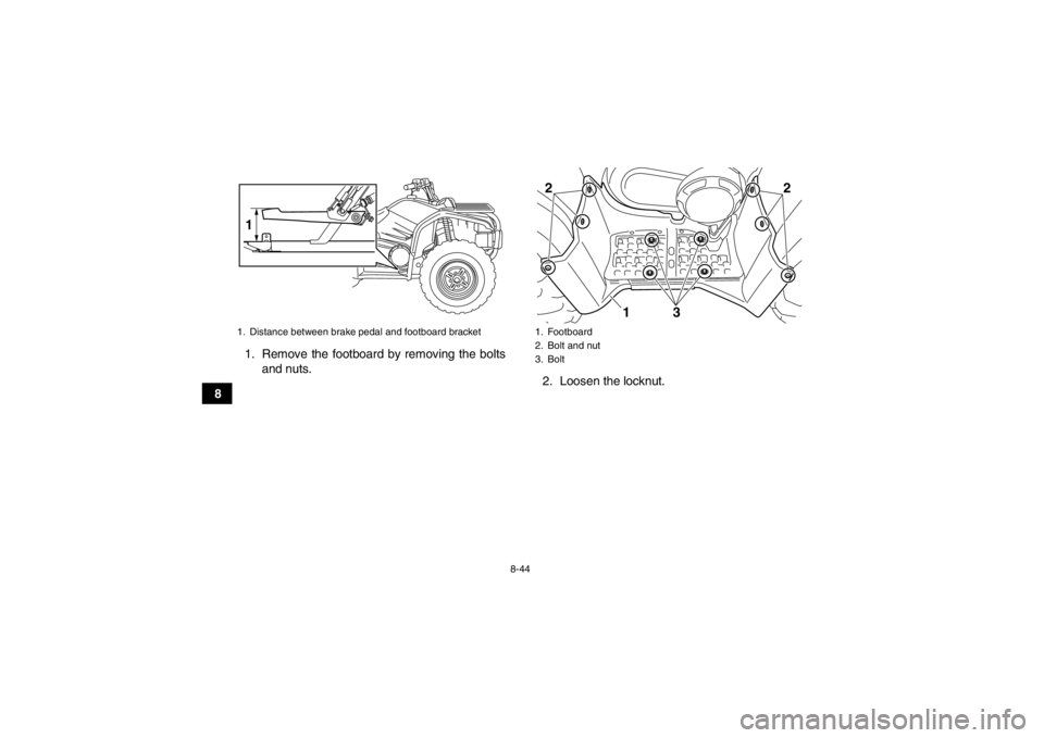
81. Remove the footboard by removing the bolts
and nuts. 2. Loosen the locknut.
1. Distance between brake pedal and footboard bracket1
1. Footboard
2. Bolt and nut
3. Bolt22
31
U1CT62E0.book Page 44 Friday, May 11, 2012 9:03 AM
Page 137 of 172
8-45
8
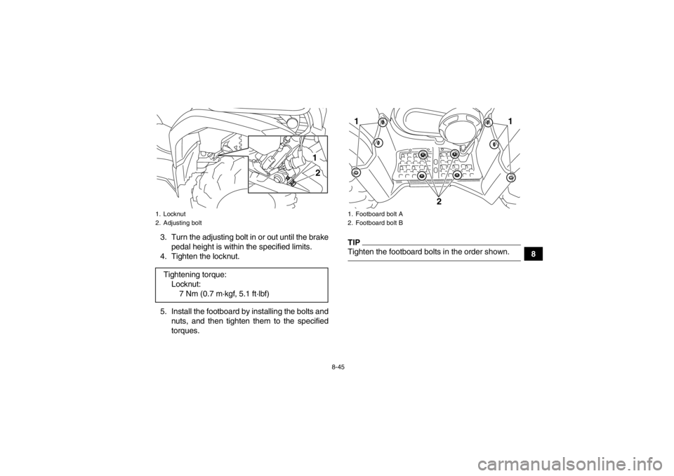
3. Turn the adjusting bolt in or out until the brake
pedal height is within the specified limits.
4. Tighten the locknut.
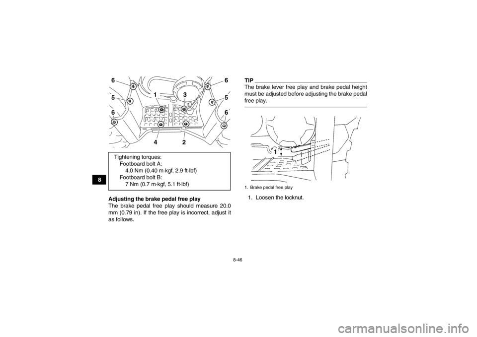
5. Install the footboard by installing the bolts and nuts, and then tighten them to the specified
torques.
TIPTighten the footboard bolts in the order shown.
1. Locknut
2. Adjusting boltTightening torque:Locknut:7 Nm (0.7 m·kgf, 5.1 ft·lbf)
21
1. Footboard bolt A
2. Footboard bolt B11
2
U1CT62E0.book Page 45 Friday, May 11, 2012 9:03 AM
Page 138 of 172
8-46
8Adjusting the brake pedal free play
The brake pedal free play should measure 20.0
mm (0.79 in). If the free play is incorrect, adjust it
as follows.
TIPThe brake lever free play and brake pedal height
must be adjusted before adjusting the brake pedal
free play.1. Loosen the locknut.
Tightening torques:
Footboard bolt A:4.0 Nm (0.40 m·kgf, 2.9 ft·lbf)
Footboard bolt B: 7 Nm (0.7 m·kgf, 5.1 ft·lbf)
656
656
2
4
3
1
1. Brake pedal free play
U1CT62E0.book Page 46 Friday, May 11, 2012 9:03 AM