rear brake adjust YAMAHA GRIZZLY 450 2013 Owners Manual
[x] Cancel search | Manufacturer: YAMAHA, Model Year: 2013, Model line: GRIZZLY 450, Model: YAMAHA GRIZZLY 450 2013Pages: 172, PDF Size: 3.96 MB
Page 9 of 172

EBU17420
TABLE OF CONTENTS
LOCATION OF THE WARNING AND
SPECIFICATION LABELS ............................ 1-1
SAFETY INFORMATION .............................. 2-1
DESCRIPTION .............................................. 3-1Left view ...................................................... 3-1
Right view.................................................... 3-1
Controls and instruments ............................ 3-2
INSTRUMENT AND CONTROL
FUNCTIONS .................................................. 4-1 Main switch ................................................ 4-1
Indicator lights and warning lights .............. 4-2
Multi-function display .................................. 4-5
Fuel gauge ................................................. 4-6
Handlebar switches .................................... 4-6
Throttle lever ............................................ 4-12
Speed limiter ............................................ 4-12
Front brake lever ...................................... 4-13
Brake pedal and rear brake lever ............. 4-13
Drive select lever ...................................... 4-14
Fuel tank cap ............................................ 4-14
Fuel .......................................................... 4-15 Fuel cock ..................................................4-16
Starter (choke) ..........................................4-18
Seat ..........................................................4-18
Storage compartments .............................4-19
Front carrier ..............................................4-22
Rear carrier ...............................................4-22
Adjusting the front and rear shock
absorber assemblies ...............................4-22
Auxiliary DC jack .......................................4-23
PRE-OPERATION CHECKS ..........................5-1 Fuel .............................................................5-3
Engine oil ....................................................5-3
Final gear oil ...............................................5-3
Differential gear oil ......................................5-3
Coolant .......................................................5-3
Front and rear brakes .................................5-3
Throttle lever ...............................................5-4
Tires ............................................................5-4
Chassis fasteners .......................................5-7
Instruments, lights and switches .................5-7
OPERATION...................................................6-1 Starting a cold engine .................................6-1U1CT62E0.book Page 1 Friday, May 11, 2012 9:03 AM
Page 10 of 172

Starting a warm engine .............................. 6-3
Operating the drive select lever and driving in reverse ...................................... 6-3
Engine break-in .......................................... 6-5
Parking ....................................................... 6-5
Parking on a slope ..................................... 6-6
Accessories and loading ............................ 6-6
RIDING YOUR ATV ...................................... 7-1 GETTING TO KNOW YOUR ATV............... 7-2
RIDE WITH CARE AND GOOD JUDGMENT .............................................. 7-2
BE CAREFUL WHERE YOU RIDE ............. 7-9
TURNING YOUR ATV .............................. 7-12
CLIMBING UPHILL ................................... 7-13
RIDING DOWNHILL.................................. 7-16
CROSSING A SLOPE............................... 7-17
CROSSING THROUGH SHALLOW WATER ................................................... 7-18
RIDING OVER ROUGH TERRAIN ........... 7-21
SLIDING AND SKIDDING ......................... 7-21
WHAT TO DO IF... .................................... 7-22
WHAT TO DO... ........................................ 7-23
PERIODIC MAINTENANCE AND
ADJUSTMENT ............................................... 8-1 Owner’s manual and tool kit ....................... 8-2 Periodic maintenance chart
for the emission control system ................8-3
General maintenance and lubrication chart ..........................................................8-5
Removing and installing panels ................8-10
Checking the spark plug ...........................8-14
Engine oil and oil filter cartridge ................8-17
Final gear oil .............................................8-21
Differential gear oil ....................................8-24
Coolant .....................................................8-26
Cleaning the air filter element ...................8-30
Cleaning the spark arrester ......................8-33
V-belt cooling duct check hose .................8-35
V-belt case drain plug ...............................8-35
Adjusting the carburetor ............................8-36
Adjusting the engine idling speed .............8-36
Adjusting the throttle lever free play .........8-37
Valve clearance ........................................8-38
Adjusting the drive select lever safety system cable ...........................................8-38
Brakes .......................................................8-38
Checking the front brake pads and rear brake friction plates .........................8-39
Checking the brake fluid level ...................8-40
Changing the brake fluid ...........................8-41
Checking the front brake lever free play ...8-41
U1CT62E0.book Page 2 Friday, May 11, 2012 9:03 AM
Page 11 of 172

Adjusting the rear brake lever and brake pedal free play, and the brake
pedal height ............................................ 8-41
Axle boots ................................................ 8-47
Brake light switches ................................. 8-48
Checking and lubricating the cables ........ 8-48
Checking and lubricating the front and rear brake levers .................................... 8-49
Checking and lubricating the brake pedal ...................................................... 8-49
Checking the wheel hub bearings ............ 8-50
Lubricating the drive shaft universal joint ......................................................... 8-50
Checking the stabilizer bushes ................ 8-51
Lubricating the rear knuckle pivots ........... 8-51
Lubricating the steering shaft ................... 8-52
Battery ...................................................... 8-52
Replacing a fuse ...................................... 8-55
Replacing a headlight bulb ....................... 8-58
Adjusting a headlight beam ...................... 8-59
Replacing the tail/brake light bulb ............ 8-60
Removing a wheel .................................... 8-61
Installing a wheel ...................................... 8-62
Troubleshooting ....................................... 8-63
Troubleshooting charts ............................. 8-64 CLEANING AND STORAGE ..........................9-1
Cleaning ......................................................9-1
Storage .......................................................9-2
SPECIFICATIONS .......................................10-1
CONSUMER INFORMATION.......................11-1 Identification numbers ...............................11-1
U1CT62E0.book Page 3 Friday, May 11, 2012 9:03 AM
Page 29 of 172
3-1
3
EBU17680
DESCRIPTION
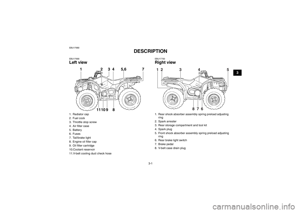
EBU17690Left view
EBU17700Right view
1. Radiator cap
2. Fuel cock
3. Throttle stop screw
4. Air filter case
5. Battery
6. Fuses
7. Tail/brake light
8. Engine oil filler cap
9. Oil filter cartridge
10.Coolant reservoir
11.V-belt cooling duct check hose
1 2 3 4 5,6 7891011
1. Rear shock absorber assembly spring preload adjusting ring
2. Spark arrester
3. Rear storage compartment and tool kit
4. Spark plug
5. Front shock absorber assembly spring preload adjusting ring
6. Rear brake light switch
7. Brake pedal
8. V-belt case drain plug1
2
3
4
5
6
7
8
U1CT62E0.book Page 1 Friday, May 11, 2012 9:03 AM
Page 43 of 172
4-13
4
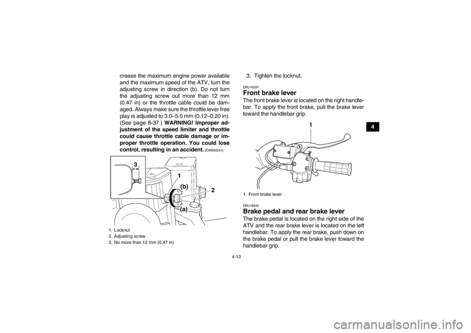
crease the maximum engine power available
and the maximum speed of the ATV, turn the
adjusting screw in direction (b). Do not turn
the adjusting screw out more than 12 mm
(0.47 in) or the throttle cable could be dam-
aged. Always make sure the throttle lever free
play is adjusted to 3.0–5.0 mm (0.12–0.20 in).
(See page 8-37.) WARNING! Improper ad-
justment of the speed limiter and throttle
could cause throttle cable damage or im-
proper throttle operation. You could lose
control, resulting in an accident.
[EWB00241]
3. Tighten the locknut.EBU18391Front brake lever The front brake lever is located on the right handle-
bar. To apply the front brake, pull the brake lever
toward the handlebar grip.EBU18442Brake pedal and rear brake lever The brake pedal is located on the right side of the
ATV and the rear brake lever is located on the left
handlebar. To apply the rear brake, push down on
the brake pedal or pull the brake lever toward the
handlebar grip.
1. Locknut
2. Adjusting screw
3. No more than 12 mm (0.47 in)
1. Front brake lever
U1CT62E0.book Page 13 Friday, May 11, 2012 9:03 AM
Page 56 of 172

5-2
5
Front brake Check operation. If soft or spongy, have Yamaha dealer bleed hy-
draulic system.
Check brake pads for wear , and replace if necessary.
Check brake fluid level in reservoir, and add specified brake fluid to specified level if necessary.
Check hydraulic system for leakage. Correct if necessary. 5-3, 8-39, 8-40, 8-41
Rear brake Check operation, and correct if necessary.
Lubricate cables if necessary.
Check lever and pedal free play, and adjust if necessary. 5-3, 8-39, 8-41
Throttle lever Make sure that operation is smooth. Lubricate cable and lever hous-
ing if necessary.
Check lever free play, and adjust if necessary. 5-4, 8-37
Control cables Make sure that operation is smooth. Lubricate if necessary. 8-48
Wheels and tires Check wheel condition, and replace if damaged.
Check tire condition and tread depth. Replace if necessary.
Check air pressure. Correct if necessary. 5-4
Brake pedal Make sure that operation is smooth. Lubricate pedal pivoting point if
necessary. 8-49
Brake levers Make sure that operation is smooth. Lubricate lever pivoting points if
necessary. 8-49
Axle boots Check for cracks or damage, and replace if necessary. 8-47
Chassis fasteners Make sure that all nuts, bolts and screws are properly tightened. 5-7
Instruments, lights and
switches Check operation, and correct if necessary. 5-7
ITEM ROUTINE PAGEU1CT62E0.book Page 2 Friday, May 11, 2012 9:03 AM
Page 97 of 172
8-5
8
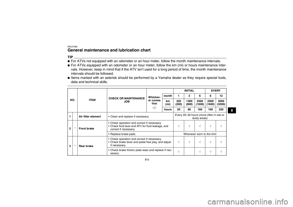
EBU21865General maintenance and lubrication chart TIP●For ATVs not equipped with an odometer or an hour meter, follow the month maintenance intervals.●For ATVs equipped with an odometer or an hour meter, follow the km (mi) or hours maintenance inter-
vals. However, keep in mind that if the ATV isn’t used for a long period of time, the month maintenance
intervals should be followed.●Items marked with an asterisk should be performed by a Yamaha dealer as they require special tools,
data and technical skills.NO.ITEM CHECK OR MAINTENANCE
JOB INITIAL
EVERY
Whichev- er comes first month136612
km
(mi) 320
(200) 1300
(800) 2500
(1600) 2500
(1600) 5000
(3200)
hours 20 80 160 160 320
1 Air filter element Clean and replace if necessary. Every 20–40 hours (more often in wet or
dusty areas)
2 *Front brake Check operation and correct if necessary.
Check fluid level and ATV for fluid leakage, and
correct if necessary. √√√√√
Replace brake pads. Whenever worn to the limit
3 *Rear brake Check operation and correct if necessary.
Check brake lever and pedal free play, and adjust
if necessary. √√√√√
Check brake friction plate wear and replace if nec- essary. √ √√√
U1CT62E0.book Page 5 Friday, May 11, 2012 9:03 AM
Page 100 of 172
8-8
8
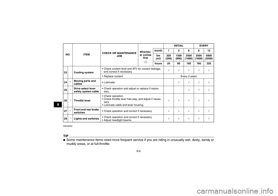
EBU28391TIP●Some maintenance items need more frequent service if you are riding in unusually wet, dusty, sandy or
muddy areas, or at full-throttle.23 Cooling system Check coolant level and ATV for coolant leakage,
and correct if necessary. √√√√√
Replace coolant. Every 2 years
24 *Moving parts and
cables Lubricate.
√√√√
25 *Drive select lever
safety system cable Check operation and adjust or replace if neces-
sary. √√√
26 *Throttle lever Check operation.
Check throttle lever free play, and adjust if neces-
sary.
Lubricate cable and lever housing. √√√√√
27 *Front and rear brake
switches Check operation and correct if necessary.
√√√√√
28 *Lights and switches Check operation and correct if necessary.
Adjust headlight beams. √√√√√
NO. ITEM
CHECK OR MAINTENANCE
JOB INITIAL EVERY
Whichev- er comes first month136612
km
(mi) 320
(200) 1300
(800) 2500
(1600) 2500
(1600) 5000
(3200)
hours 20 80 160 160 320U1CT62E0.book Page 8 Friday, May 11, 2012 9:03 AM
Page 133 of 172
8-41
8
brake pads for wear and the brake system for leak-
age. If the brake fluid level goes down suddenly,
have a Yamaha dealer check the cause before fur-
ther riding.
EBU24281Changing the brake fluid Have a Yamaha dealer change the brake fluid at
the intervals specified in the TIP after the periodic
maintenance and lubrication chart. In addition,
have the oil seals of the brake master cylinder and
calipers as well as the brake hoses replaced at the
intervals listed below or whenever they are dam-
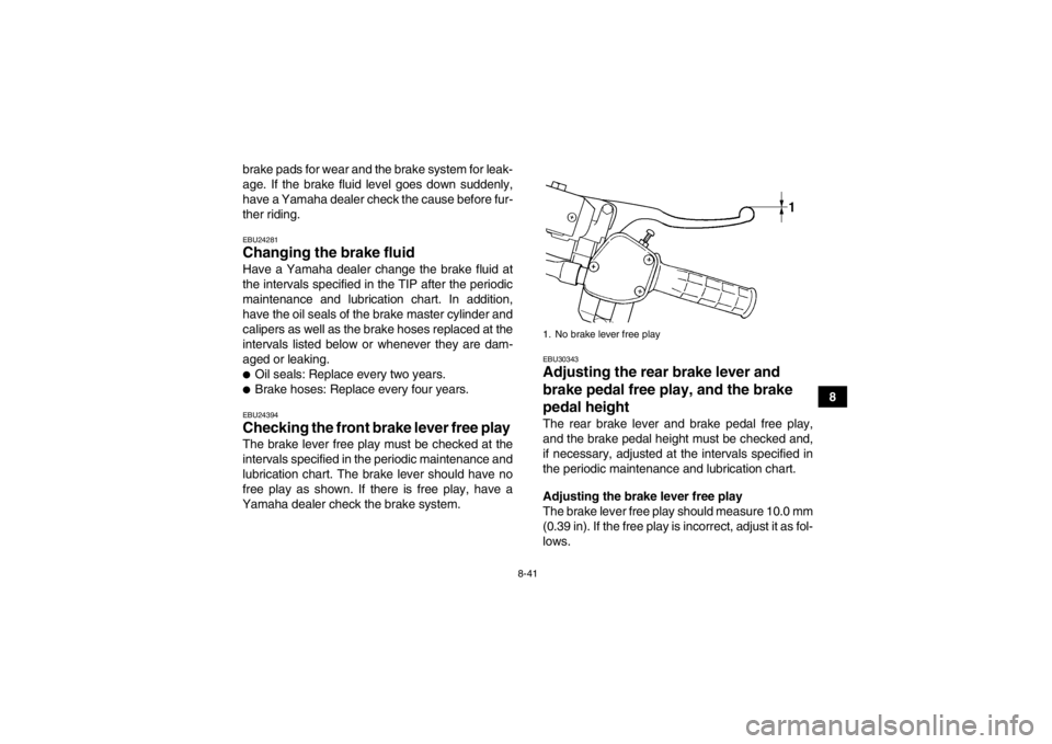
aged or leaking.●Oil seals: Replace every two years.●Brake hoses: Replace every four years.EBU24394Checking the front brake lever free play The brake lever free play must be checked at the
intervals specified in the periodic maintenance and
lubrication chart. The brake lever should have no
free play as shown. If there is free play, have a
Yamaha dealer check the brake system.
EBU30343Adjusting the rear brake lever and
brake pedal free pl ay, and the brake
pedal height The rear brake lever and brake pedal free play,
and the brake pedal height must be checked and,
if necessary, adjusted at the intervals specified in
the periodic maintenance and lubrication chart.
Adjusting the brake lever free play
The brake lever free play should measure 10.0 mm
(0.39 in). If the free play is incorrect, adjust it as fol-
lows.1. No brake lever free play
U1CT62E0.book Page 41 Friday, May 11, 2012 9:03 AM
Page 139 of 172
8-47
8
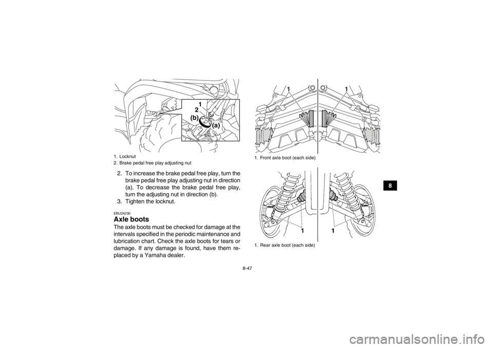
2. To increase the brake pedal free play, turn the
brake pedal free play adjusting nut in direction
(a). To decrease the brake pedal free play,
turn the adjusting nut in direction (b).
3. Tighten the locknut.
EBU24230Axle boots The axle boots must be checked for damage at the
intervals specified in the periodic maintenance and
lubrication chart. Check the axle boots for tears or
damage. If any damage is found, have them re-
placed by a Yamaha dealer.1. Locknut
2. Brake pedal free play adjusting nut
21
(a)
(b)
1. Front axle boot (each side)
1. Rear axle boot (each side)
1
1
U1CT62E0.book Page 47 Friday, May 11, 2012 9:03 AM