YAMAHA GRIZZLY 450 2015 Owners Manual
Manufacturer: YAMAHA, Model Year: 2015, Model line: GRIZZLY 450, Model: YAMAHA GRIZZLY 450 2015Pages: 170, PDF Size: 3.93 MB
Page 161 of 170

10-1
10
EBU25962
SPECIFICATIONS
Dimensions:Overall length:1993 mm (78.5 in)
Overall width: 1093 mm (43.0 in)
Overall height:
1120 mm (44.1 in)
Seat height: 840 mm (33.1 in)
Wheelbase: 1233 mm (48.5 in)
Ground clearance:
245 mm (9.6 in)
Minimum turning radius: 3000 mm (118 in)Weight:Curb weight:
YFM450DF 275.0 kg (606 lb) (AUS)(NZL)
YFM450DF 276.0 kg (608 lb) (EUR)(FRA)(GBR)
YFM450PF 281.0 kg (619 lb) (AUS)(NZL)
YFM450PF 282.0 kg (622 lb) (EUR)(FRA)(GBR)
YFM450PHF 282.0 kg (622 lb)Noise and vibration level:Noise level (77/311/EEC):YFM450DF 78.3 dB(A) (EUR)(FRA)(GBR)
YFM450PF 78.3 dB(A) (EUR)(FRA)(GBR)
YFM450PHF 78.3 dB(A) Vibration on seat (EN1032, ISO5008):
YFM450DF 0.6 m/s² (EUR)(FRA)(GBR)
YFM450PF 0.6 m/s² (EUR)(FRA)(GBR)
YFM450PHF 0.6 m/s²
Vibration on handle (EN1032, ISO5008): YFM450DF Will not exceed 2.5 m/s² (EUR)(FRA)(GBR)
YFM450PF Will not exceed 2.5 m/s² (EUR)(FRA)(GBR)
YFM450PHF Will not exceed 2.5 m/s²
Engine:Engine type:Liquid cooled 4-stroke, SOHC
Cylinder arrangement:
Single cylinder
Displacement: 421 cm³
Bore × stroke:
84.5 × 75.0 mm (3.33 × 2.95 in)
Compression ratio:
10.0 : 1
Starting system: Electric starter
Lubrication system: Wet sumpEngine oil:Recommended brand:YAMALUBE
U2LC61E0.book Page 1 Wednesday, February 26, 2014 3:56 PM
Page 162 of 170

10-2
10
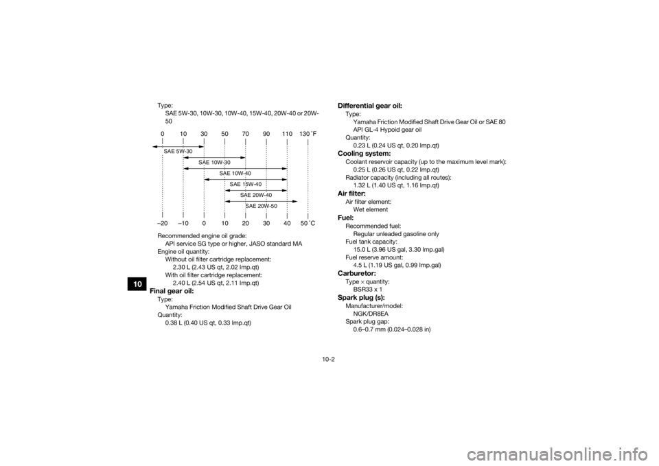
Type:SAE 5W-30, 10W-30, 10W-40, 15W-40, 20W-40 or 20W-
50
Recommended engine oil grade: API service SG type or higher, JASO standard MA
Engine oil quantity: Without oil filter cartridge replacement: 2.30 L (2.43 US qt, 2.02 Imp.qt)
With oil filter cartridge replacement: 2.40 L (2.54 US qt, 2.11 Imp.qt)Final gear oil:Type:Yamaha Friction Modified Shaft Drive Gear Oil
Quantity: 0.38 L (0.40 US qt, 0.33 Imp.qt)
Differential gear oil:Type:Yamaha Friction Modified Shaft Drive Gear Oil or SAE 80
API GL-4 Hypoid gear oil
Quantity: 0.23 L (0.24 US qt, 0.20 Imp.qt)Cooling system:Coolant reservoir capacity (up to the maximum level mark):0.25 L (0.26 US qt, 0.22 Imp.qt)
Radiator capacity (including all routes): 1.32 L (1.40 US qt, 1.16 Imp.qt)Air filter:Air filter element:Wet elementFuel:Recommended fuel:
Regular unleaded gasoline only
Fuel tank capacity: 15.0 L (3.96 US gal, 3.30 Imp.gal)
Fuel reserve amount: 4.5 L (1.19 US gal, 0.99 Imp.gal)Carburetor:Type × quantity:
BSR33 x 1Spark plug (s):Manufacturer/model:
NGK/DR8EA
Spark plug gap: 0.6–0.7 mm (0.024–0.028 in)
0 10 30 50 70 90 110 130 �F
–20 –10 0 10 20 30 40 50 �CSAE 5W-30
SAE 10W-30
SAE 10W-40
SAE 15W-40
SAE 20W-40SAE 20W-50
U2LC61E0.book Page 2 Wednesday, February 26, 2014 3:56 PM
Page 163 of 170

10-3
10
Clutch:Clutch type:Wet, centrifugal automaticTransmission:Primary reduction system:V-belt
Secondary reduction system: Shaft drive
Secondary reduction ratio:
39/24 × 24/18 × 33/9 (7.944)
Transmission type: V-belt automatic
Operation: Left hand operation
Reverse gear:
29/17 (1.706)
Low range: 45/16 (2.813)
High range: 38/23 (1.652)Chassis:Frame type:Steel tube frame
Caster angle: 2.5 °
Trail:
8.5 mm (0.33 in)Front tire:Type:Tubeless Size:
AT25 x 8-12
Manufacturer/model: YFM450DF CHENG SHIN/C-828 (AUS)(NZL)
YFM450DF MAXXIS/MU13 (EUR)(FRA)(GBR)
YFM450PF CHENG SHIN/C-828 (AUS)(NZL)
YFM450PF MAXXIS/MU13 (EUR)(FRA)(GBR)
YFM450PHF MAXXIS/MU13
Rear tire:Type:
Tubeless
Size: AT25 x 10-12
Manufacturer/model: YFM450DF CHENG SHIN/C-828 (AUS)(NZL)
YFM450DF MAXXIS/MU14 (EUR)(FRA)(GBR)
YFM450PF CHENG SHIN/C-828 (AUS)(NZL)
YFM450PF MAXXIS/MU14 (EUR)(FRA)(GBR)
YFM450PHF MAXXIS/MU14Loading:Maximum loading limit:
210.0 kg (463 lb)
(Total weight of rider, cargo, accessories, and tongue)Tire air pressure (measured on cold tires):Recommended:Front:
25.0 kPa (0.250 kgf/cm², 3.6 psi)
Rear: 25.0 kPa (0.250 kgf/cm², 3.6 psi)
Minimum: Front:22.0 kPa (0.220 kgf/cm², 3.2 psi)
U2LC61E0.book Page 3 Wednesday, February 26, 2014 3:56 PM
Page 164 of 170

10-4
10
Rear:22.0 kPa (0.220 kgf/cm², 3.2 psi)
Front wheel:Wheel type:
Panel wheel
Rim size: 12 x 6.0ATRear wheel:Wheel type:
Panel wheel
Rim size: 12 x 7.5ATFront brake:Type:
Disc brake
Operation: Right hand operation
Specified brake fluid: DOT 4Rear brake:Type:Wet multiple disc brake
Operation: Left hand and right foot operationFront suspension:Type:Double wishbone
Spring/shock absorber type: Coil spring/oil damper
Wheel travel:
160 mm (6.3 in)
Rear suspension:Type:Double wishbone
Spring/shock absorber type:
Coil spring/oil damper
Wheel travel: 180 mm (7.1 in)Electrical system:Ignition system:
DC CDI
Charging system: AC magnetoBattery:Model:
YTX20L-BS
Voltage, capacity: 12 V, 18.0 AhHeadlight:Bulb type:
Krypton bulbBulb voltage, wattage × quantity:Headlight:
12 V, 30.0/30.0 W × 2
Tail/brake light:
12 V, 5.0/21.0 W × 1
Meter lighting: EL (Electroluminescent)
Neutral indicator light: LED
Reverse indicator light:
LED
U2LC61E0.book Page 4 Wednesday, February 26, 2014 3:56 PM
Page 165 of 170

10-5
10
Coolant temperature warning light:LED
Park indicator light: LED
On-Command four-wheel-drive/differential gear lock
indicator: LCD
High-range indicator light:
LED
Low-range indicator light: LED
Differential gear lock indicator light: LED
EPS warning light:
YFM450PF 12 V, 1.7 W
YFM450PHF 12 V, 1.7 WFuses:Main fuse:30.0 A
EPS fuse: YFM450PF 40.0 A
YFM450PHF 40.0 A
Headlight fuse: 15.0 A
Signaling system fuse:
10.0 A
Ignition fuse: 10.0 A
Auxiliary DC jack fuse: 10.0 A Backup fuse:
YFM450DF 10.0 A
YFM450PF 5.0 A
YFM450PHF 5.0 A
Four-wheel-drive motor fuse:
10.0 A
EBU30402For Europe only
The figures quoted are emission levels and are not
necessarily safe working levels. Whilst there is a
correlation between the emission and exposure
levels, this cannot be used reliably to determine
whether or not further precautions are required.
Factors that influence the actual level of exposure
of work-force include the characteristics of the
work room, the other sources of noise, etc. i.e. the
number of machines and other adjacent process-
es, and the length of time for which an operator is
exposed to the noise. Also the permissible expo-
sure level can vary from country. This information,
however, will enable the user of the machine to
make a better evaluation of the hazard and risk.
U2LC61E0.book Page 5 Wednesday, February 26, 2014 3:56 PM
Page 166 of 170

11-1
11
EBU26001
CONSUMER INFORMATION
EBU28202Identification numbersRecord the vehicle identification number and
model label information in the spaces provided
below for assistance when ordering spare parts
from a Yamaha dealer or for reference in case the
ATV is stolen.
VEHICLE IDENTIFICATION NUMBER:
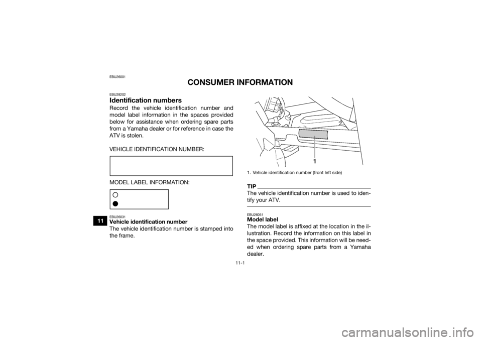
MODEL LABEL INFORMATION:EBU26031Vehicle identification number
The vehicle identification number is stamped into
the frame.
TIPThe vehicle identification number is used to iden-
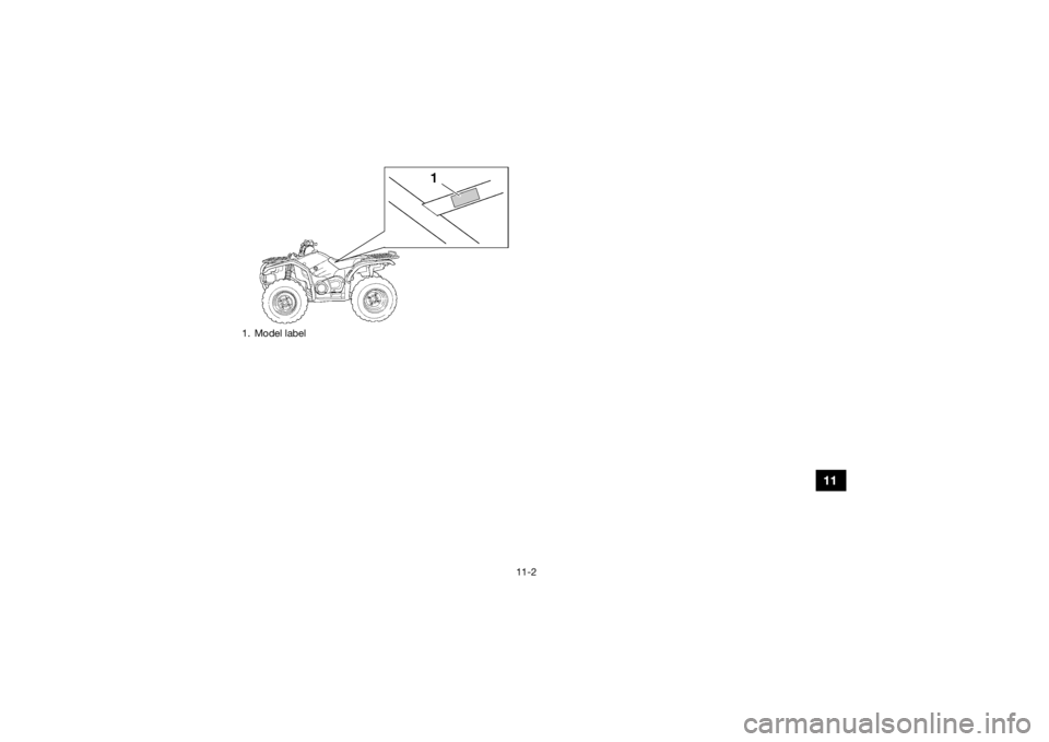
tify your ATV. EBU26051Model label
The model label is affixed at the location in the il-
lustration. Record the information on this label in
the space provided. This information will be need-
ed when ordering spare parts from a Yamaha
dealer.1. Vehicle identification number (front left side)
U2LC61E0.book Page 1 Wednesday, February 26, 2014 3:56 PM
Page 167 of 170

11-2
11
1. Model labelU2LC61E0.book Page 2 Wednesday, February 26, 2014 3:56 PM
Page 168 of 170

12-1
12
INDEX
AAccessories and loading ................................................ 6-6
Accessories, auxiliary jack ........................................... 4-24
Air filter element, cleaning ............................................ 8-30
Axle boots .................................................................... 8-46BBattery .......................................................................... 8-52
Brake fluid, changing ...................................................8-40
Brake fluid level, checking ........................................... 8-39
Brake lever free play, checking the front ..................... 8-40
Brake lever, front .......................................................... 4-14
Brake levers, checking and lubricating ........................ 8-48
Brake light switches ..................................................... 8-47
Brake pads and friction plates, checking ..................... 8-38
Brake pedal and rear brake lever ................................. 4-14
Brake pedal, checking and lubricating ........................ 8-49
Brakes .......................................................................... 8-38
Brakes, front and rear .................................................... 5-3CCables, checking and lubricating ................................. 8-48
Carburetor, adjusting ...................................................8-35
Carrier, front ................................................................. 4-22
Carrier, rear .................................................................. 4-22
Chassis fasteners ........................................................... 5-7
Cleaning ......................................................................... 9-1
Coolant ................................................................. 5-3, 8-26
Coolant temperature warning light ................................. 4-3DDifferential gear oil ............................................... 5-3, 8-24Drive select lever .......................................................... 4-15
Drive select lever and driving in reverse ........................ 6-3
Drive select lever safety system cable, adjusting ........ 8-38
Drive shaft universal joint, lubricating .......................... 8-50
EEngine break-in .............................................................. 6-5
Engine, cold start ........................................................... 6-1
Engine idling speed ...................................................... 8-35
Engine oil ....................................................................... 5-3
Engine oil and oil filter cartridge .................................. 8-16
Engine, starting a warm ................................................. 6-3
Engine stop switch ......................................................... 4-7
EPS warning light (for EPS model) ................................. 4-3FFinal gear oil ......................................................... 5-3, 8-21
Four-wheel-drive/differential gear lock indicator ........... 4-4
Fuel ...................................................................... 4-15, 5-3
Fuel cock ...................................................................... 4-17
Fuel gauge ..................................................................... 4-6
Fuel tank cap ............................................................... 4-15
Fuses, replacing ........................................................... 8-55HHandlebar switches ....................................................... 4-7
Headlight beam, adjusting ........................................... 8-59
Headlight bulb, replacing ............................................. 8-58
High-range indicator light .............................................. 4-2
Horn switch .................................................................... 4-7IIdentification numbers ................................................. 11-1
U2LC61E0.book Page 1 Wednesday, February 26, 2014 3:56 PM
Page 169 of 170

12-2
12
Indicator lights and warning lights ................................. 4-2
Instruments, lights and switches ................................... 5-7LLabel locations ............................................................... 1-1
Light switch .................................................................... 4-7
Low-range indicator light ............................................... 4-2MMain switch .................................................................... 4-1
Maintenance and lubrication chart ................................ 8-5
Maintenance chart, emission control system ................ 8-3
Model label .................................................................. 11-1
Multi-function display .................................................... 4-5NNeutral indicator light ..................................................... 4-2OOn-Command differential gear lock switch ................. 4-10
On-Command four-wheel-drive switch ......................... 4-9
Override switch .............................................................. 4-8
Owner’s manual and tool kit .......................................... 8-2PPanels, removing and installing ................................... 8-10
Park indicator light ......................................................... 4-3
Parking ........................................................................... 6-5
Parking on a slope ......................................................... 6-6
Part locations ................................................................. 3-1RRear brake, adjusting the lever, pedal free play and pedal height ............................................................... 8-41
Rear knuckle pivots, lubricating .................................. 8-51
Reverse indicator light ................................................... 4-3
Riding your ATV ............................................................. 7-1
SSafety information .......................................................... 2-1
Seat .............................................................................. 4-19
Shock absorber assemblies, adjusting the front and
rear ............................................................................ 4-22
Spark arrester, cleaning ............................................... 8-33
Spark plug, checking ................................................... 8-14
Specifications .............................................................. 10-1
Speed limiter ................................................................ 4-13
Stabilizer bushes, checking .......... ............................... 8-51
Starter (choke) ............................................................. 4-18
Start switch .................................................................... 4-7
Steering shaft, lubricating ............................................ 8-52
Storage .......................................................................... 9-2
Storage compartments ................................................ 4-20TTail/brake light bulb, replacing .................................... 8-60
Throttle lever ......................................................... 4-12, 5-4
Throttle lever free play, adjusting ................................ 8-37
Tires ............................................................................... 5-4
Troubleshooting ........................................................... 8-63
Troubleshooting charts ................................................ 8-64VValve clearance ............................................................ 8-37
V-belt case drain plug .................................................. 8-35
V-belt cooling duct check hose ................................... 8-34
Vehicle identification number ...................................... 11-1WWheel hub bearings, checking .................................... 8-49
Wheel, installing ........................................................... 8-62
Wheel, removing .......................................................... 8-61
U2LC61E0.book Page 2 Wednesday, February 26, 2014 3:56 PM
Page 170 of 170

EBU26173
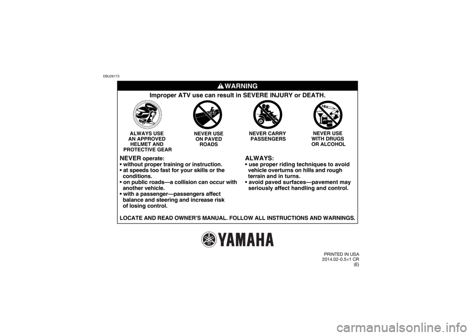
WARNING
ALWAYS
:
vehicle overturns on hills and rough
terrain and in turns.
seriously affect handling and control.
Improper ATV use can result in SEVERE INJURY or DEATH.
NEVER USE
WITH DRUGS
OR ALCOHOL
ALWAYS USE
AN APPROVED HELMET AND
PROTECTIVE GEAR NEVER USE
ON PAVED ROADS NEVER CARRY
PASSENGERS
NEVER
operate:
conditions.
another vehicle.
balance and steering and increase risk
of losing control.
LOCATE AND READ OWNER’S MANUAL. FOLLOW ALL INSTRUCTIONS AND WARNINGS.\
PRINTED IN USA
2014.02-0.5× 1 CR
(E)
U2LC61E0.book Page 1 Wednesday, February 26, 2014 3:56 PM