YAMAHA GRIZZLY 550 2010 Owners Manual
Manufacturer: YAMAHA, Model Year: 2010, Model line: GRIZZLY 550, Model: YAMAHA GRIZZLY 550 2010Pages: 168, PDF Size: 6.49 MB
Page 161 of 168
10-4
10
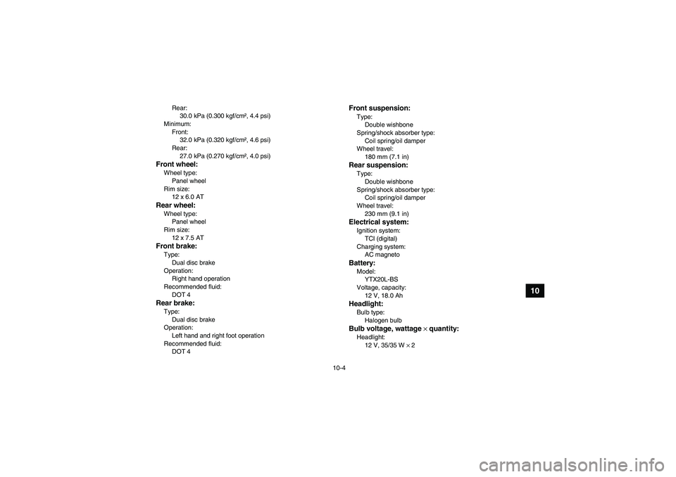
Rear:
30.0 kPa (0.300 kgf/cm², 4.4 psi)
Minimum:
Front:
32.0 kPa (0.320 kgf/cm², 4.6 psi)
Rear:
27.0 kPa (0.270 kgf/cm², 4.0 psi)
Front wheel:Wheel type:
Panel wheel
Rim size:
12 x 6.0 ATRear wheel:Wheel type:
Panel wheel
Rim size:
12 x 7.5 ATFront brake:Type:
Dual disc brake
Operation:
Right hand operation
Recommended fluid:
DOT 4Rear brake:Type:
Dual disc brake
Operation:
Left hand and right foot operation
Recommended fluid:
DOT 4
Front suspension:Type:
Double wishbone
Spring/shock absorber type:
Coil spring/oil damper
Wheel travel:
180 mm (7.1 in)Rear suspension:Type:
Double wishbone
Spring/shock absorber type:
Coil spring/oil damper
Wheel travel:
230 mm (9.1 in)Electrical system:Ignition system:
TCI (digital)
Charging system:
AC magnetoBattery:Model:
YTX20L-BS
Voltage, capacity:
12 V, 18.0 AhHeadlight:Bulb type:
Halogen bulbBulb voltage, wattage × quantity:Headlight:
12 V, 35/35 W × 2
U28P61E0.book Page 4 Wednesday, March 18, 2009 9:25 AM
Page 162 of 168
10-5
10
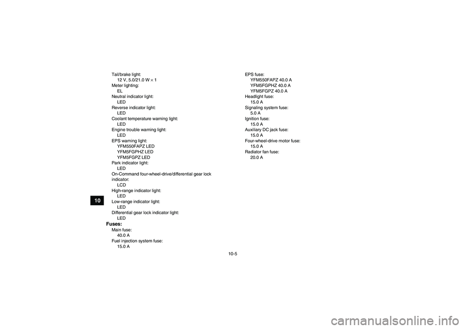
Tail/brake light:
12 V, 5.0/21.0 W × 1
Meter lighting:
EL
Neutral indicator light:
LED
Reverse indicator light:
LED
Coolant temperature warning light:
LED
Engine trouble warning light:
LED
EPS warning light:
YFM550FAPZ LED
YFM5FGPHZ LED
YFM5FGPZ LED
Park indicator light:
LED
On-Command four-wheel-drive/differential gear lock
indicator:
LCD
High-range indicator light:
LED
Low-range indicator light:
LED
Differential gear lock indicator light:
LEDFuses:Main fuse:
40.0 A
Fuel injection system fuse:
15.0 AEPS fuse:
YFM550FAPZ 40.0 A
YFM5FGPHZ 40.0 A
YFM5FGPZ 40.0 A
Headlight fuse:
15.0 A
Signaling system fuse:
5.0 A
Ignition fuse:
15.0 A
Auxiliary DC jack fuse:
15.0 A
Four-wheel-drive motor fuse:
15.0 A
Radiator fan fuse:
20.0 A
U28P61E0.book Page 5 Wednesday, March 18, 2009 9:25 AM
Page 163 of 168
11-1
11
EBU26000
CONSUMER INFORMATION
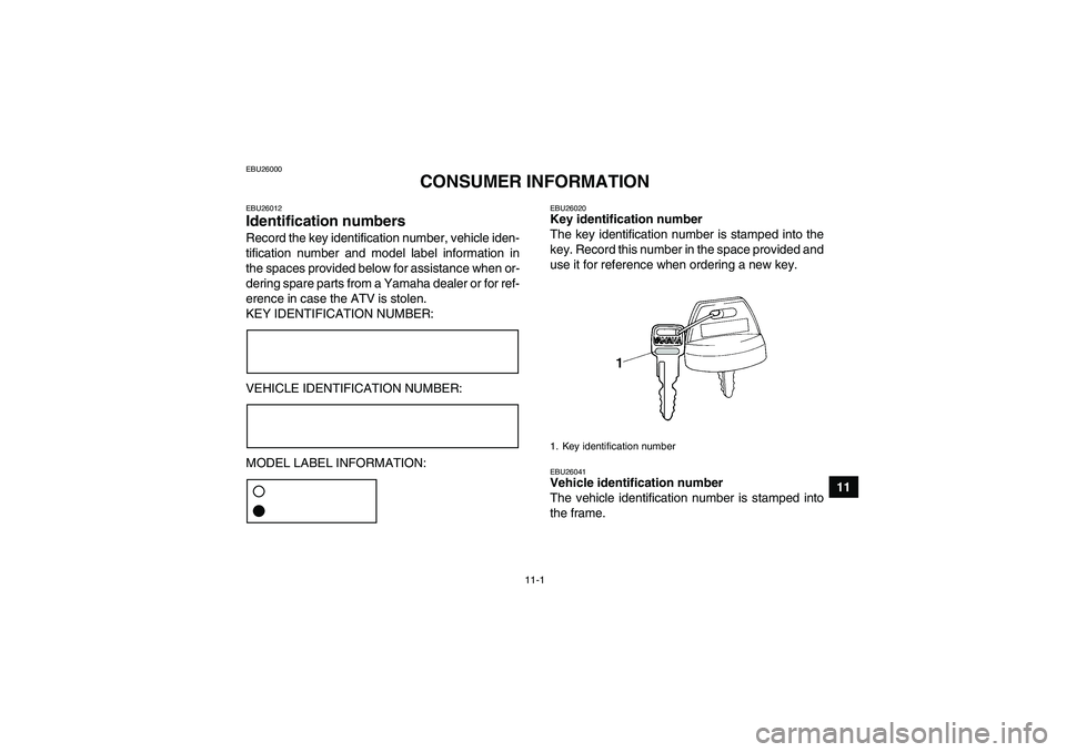
EBU26012Identification numbers Record the key identification number, vehicle iden-
tification number and model label information in
the spaces provided below for assistance when or-
dering spare parts from a Yamaha dealer or for ref-
erence in case the ATV is stolen.
KEY IDENTIFICATION NUMBER:
VEHICLE IDENTIFICATION NUMBER:
MODEL LABEL INFORMATION:
EBU26020Key identification number
The key identification number is stamped into the
key. Record this number in the space provided and
use it for reference when ordering a new key.EBU26041Vehicle identification number
The vehicle identification number is stamped into
the frame.1. Key identification number
U28P61E0.book Page 1 Wednesday, March 18, 2009 9:25 AM
Page 164 of 168
11-2
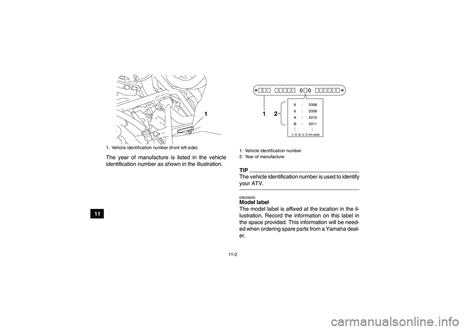
11The year of manufacture is listed in the vehicle
identification number as shown in the illustration.
TIPThe vehicle identification number is used to identify
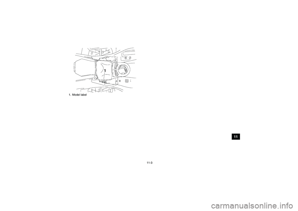
your ATV.EBU26050Model label
The model label is affixed at the location in the il-
lustration. Record the information on this label in
the space provided. This information will be need-
ed when ordering spare parts from a Yamaha deal-
er.
1. Vehicle identification number (front left side)
1. Vehicle identification number
2. Year of manufacture
00
8 : 2008
9 : 2009
A : 2010
B : 2011(I, O, Q, U, Z not used)
12
U28P61E0.book Page 2 Wednesday, March 18, 2009 9:25 AM
Page 165 of 168
11-3
11
1. Model labelU28P61E0.book Page 3 Wednesday, March 18, 2009 9:25 AM
Page 166 of 168
INDEX
AAccessories and loading ................................................ 6-6
Accessories, auxiliary jack ........................................... 4-23
Air filter element, cleaning ............................................ 8-36
Axle boots .................................................................... 8-49BBattery .......................................................................... 8-53
Brake fluid, changing .................................................... 8-46
Brake fluid level, checking ............................................ 8-45
Brake hose protectors, checking the rear .................... 8-44
Brake lever, front .......................................................... 4-14
Brake levers, checking and lubricating ......................... 8-50
Brake pads, checking the front and rear ...................... 8-43
Brake pedal and rear brake lever ................................. 4-14
Brake pedal, checking and lubricating ......................... 8-51
Brake pedal free play, adjusting ................................... 8-47
Brakes .......................................................................... 8-43
Brakes, front and rear .................................................... 5-3CCables, checking and lubricating ................................. 8-50
Carrier, front ................................................................. 4-21
Carrier, rear .................................................................. 4-21
Chassis fasteners ........................................................... 5-7
Cleaning ......................................................................... 9-1
Coolant .................................................................. 5-3, 8-30
Coolant temperature warning light ................................. 4-2DDifferential gear oil ................................................ 5-3, 8-28Drive select lever .......................................................... 4-15
Drive select lever and driving in reverse ........................ 6-2
Drive select lever safety system cable, adjusting ......... 8-43
EEngine break-in .............................................................. 6-4
Engine oil ....................................................................... 5-3
Engine oil and oil filter cartridge ................................... 8-22
Engine stop switch ......................................................... 4-7
Engine trouble warning light ........................................... 4-3
EPS warning light (for EPS model) ................................ 4-3FFinal gear oil .......................................................... 5-3, 8-26
Four-wheel-drive/differential gear lock indicator ............ 4-4
Front and rear brake lever free play, checking ............. 8-46
Fuel ....................................................................... 4-16, 5-3
Fuel tank cap ................................................................ 4-15
Fuses, replacing ........................................................... 8-56HHandlebar switches ........................................................ 4-7
Headlight beam, adjusting ............................................ 8-59
Headlight bulb, replacing .............................................. 8-58
High-range indicator light ............................................... 4-4
Horn switch .................................................................... 4-8IIdentification numbers .................................................. 11-1
Indicator lights and warning lights .................................. 4-2
Instruments, lights and switches .................................... 5-7
U28P61E0.book Page 1 Wednesday, March 18, 2009 9:25 AM
Page 167 of 168
KKey identification number ............................................. 11-1LLabel locations ............................................................... 1-1
Light switch .................................................................... 4-8
Low-range indicator light ................................................ 4-4MMain switch .................................................................... 4-1
Maintenance and lubrication chart ................................. 8-4
Maintenance chart, emission control system ................. 8-3
Model label ................................................................... 11-2
Multi-function display ..................................................... 4-5NNeutral indicator light ..................................................... 4-2OOn-Command differential gear lock switch .................. 4-10
On-Command four-wheel-drive switch ........................... 4-9
Override switch .............................................................. 4-8
Owner’s manual and tool kit ........................................... 8-1PPanels, removing and installing ..................................... 8-8
Park indicator light ......................................................... 4-4
Parking ........................................................................... 6-5
Parking on a slope ......................................................... 6-5
Part locations ................................................................. 3-1RRadiator grills, removing .............................................. 8-19
Rear knuckle pivots, lubricating ................................... 8-52
Reverse indicator light ................................................... 4-2
Riding your ATV ............................................................. 7-1
SSafety information .......................................................... 2-1
Seat ............................................................................. 4-18
Shock absorber assemblies, adjusting the front and
rear ............................................................................ 4-21
Spark arrester, cleaning ............................................... 8-40
Spark plug, checking ................................................... 8-20
Specifications ............................................................... 10-1
Speed limiter ................................................................ 4-13
Stabilizer bushes, checking ......................................... 8-52
Starting the engine ......................................................... 6-1
Start switch .................................................................... 4-8
Steering shaft, lubricating ............................................ 8-52
Storage .......................................................................... 9-2
Storage compartments ................................................ 4-18TTail/brake light bulb, replacing ..................................... 8-60
Throttle cable free play, adjusting ................................ 8-42
Throttle lever ......................................................... 4-13, 5-4
Tires ............................................................................... 5-4
Troubleshooting ........................................................... 8-62
Troubleshooting charts ................................................ 8-63VValve clearance ........................................................... 8-43
V-belt case drain plug .................................................. 8-41
Vehicle identification number ....................................... 11-1WWheel hub bearings, checking ..................................... 8-52
Wheel, installing ........................................................... 8-61
Wheel, removing .......................................................... 8-61
U28P61E0.book Page 2 Wednesday, March 18, 2009 9:25 AM
Page 168 of 168
YAMAHA MOTOR CO., LTD.
PRINTED ON RECYCLED PAPER PRINTED IN JAPAN
2009.03-0.3×1 CR
(E)
U28P61E0.book Page 1 Wednesday, March 18, 2009 9:25 AM