YAMAHA GRIZZLY 550 2012 Owners Manual
GRIZZLY 550 2012
YAMAHA
YAMAHA
https://www.carmanualsonline.info/img/51/50414/w960_50414-0.png
YAMAHA GRIZZLY 550 2012 Owners Manual
Trending: fuse, AUX, auxiliary battery, technical specifications, radiator cap, coolant temperature, traction control
Page 101 of 172
8-12
8
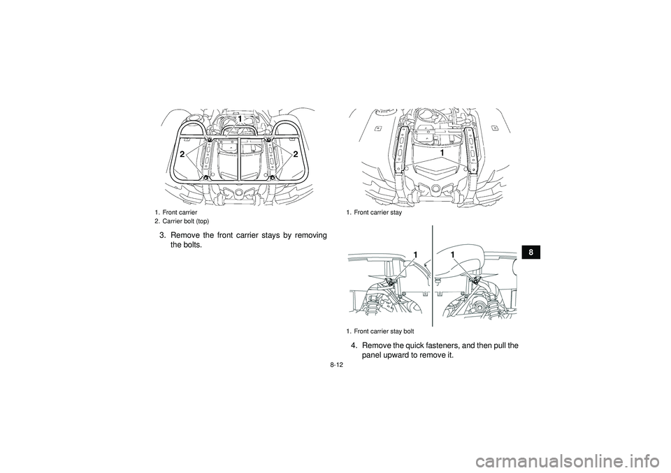
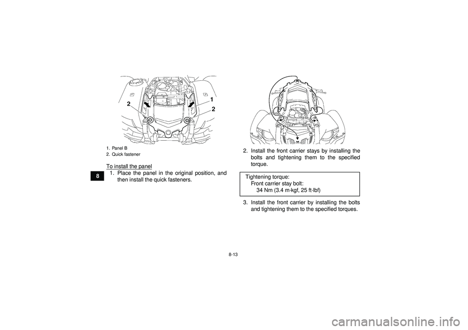
3. Remove the front carrier stays by removing
the bolts.
4. Remove the quick fasteners, and then pull thepanel upward to remove it.
1. Front carrier
2. Carrier bolt (top)
1. Front carrier stay
1. Front carrier stay bolt
U1HS60E0.book Page 12 Tuesday, April 26, 2011 7:53 PM
Page 102 of 172
8-13
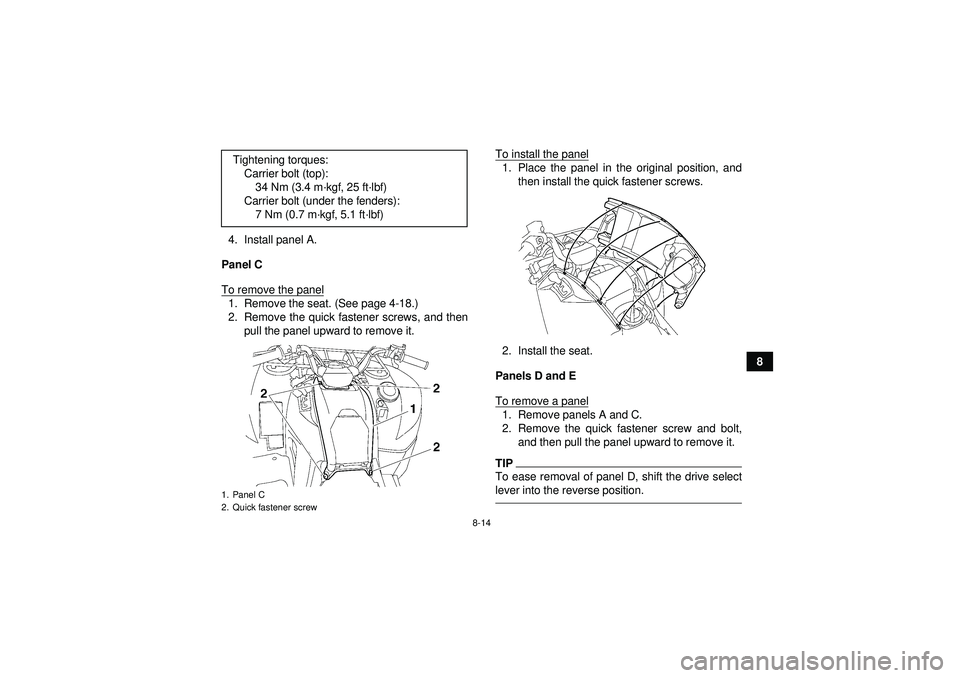
8To install the panel
1. Place the panel in the original position, and
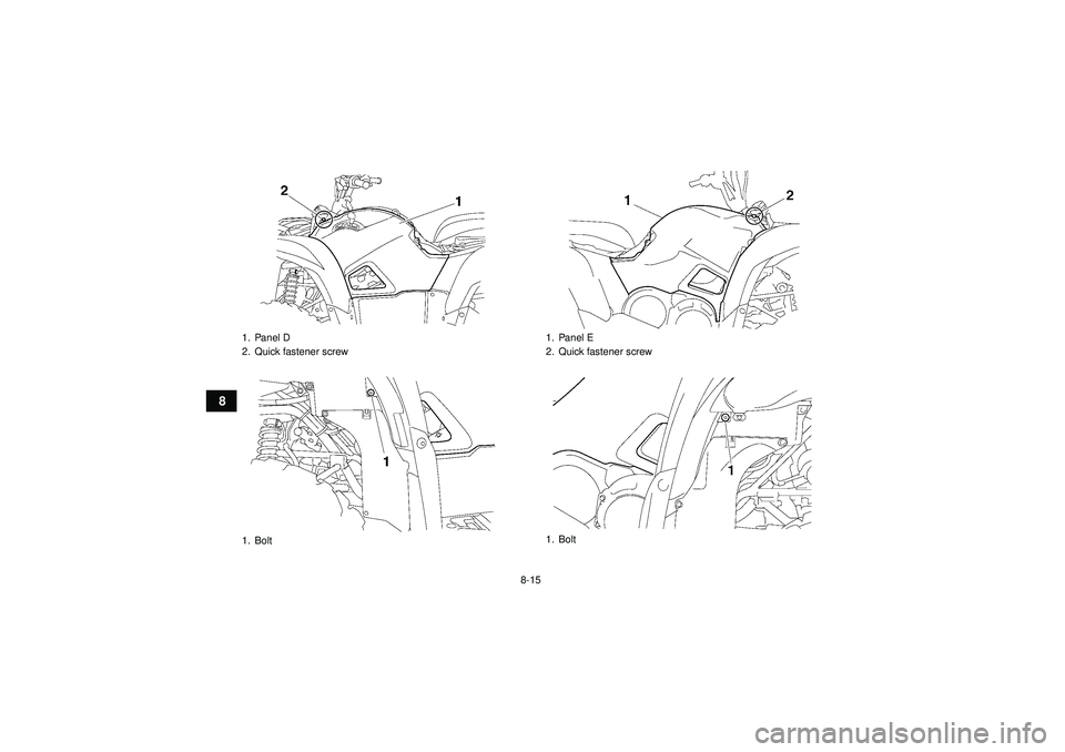
then install the quick fasteners. 2. Install the front carrier stays by installing the
bolts and tightening them to the specified
torque.
3. Install the front carrier by installing the bolts and tightening them to the specified torques.1. Panel B
2. Quick fastener
Tightening torque:Front carrier stay bolt:34 Nm (3.4 m ·kgf, 25 ft· lbf)
U1HS60E0.book Page 13 Tuesday, April 26, 2011 7:53 PM
Page 103 of 172
8-14
8
4. Install panel A.
Panel C
To remove the panel
1. Remove the seat. (See page 4-18.)
2. Remove the quick fastener screws, and then pull the panel upward to remove it. To install the panel
1. Place the panel in the original position, and
then install the quick fastener screws.
2. Install the seat.
Panels D and E
To remove a panel1. Remove panels A and C.
2. Remove the quick fastener screw and bolt, and then pull the panel upward to remove it.TIPTo ease removal of panel D, shift the drive select
lever into the reverse position.
Tightening torques:Carrier bolt (top):34 Nm (3.4 m ·kgf, 25 ft ·lbf)
Carrier bolt (under the fenders): 7 Nm (0.7 m ·kgf, 5.1 ft ·lbf)1. Panel C
2. Quick fastener screwU1HS60E0.book Page 14 Tuesday, April 26, 2011 7:53 PM
Page 104 of 172
8-15
8
1. Panel D
2. Quick fastener screw
1. Bolt
1. Panel E
2. Quick fastener screw
1. Bolt
U1HS60E0.book Page 15 Tuesday, April 26, 2011 7:53 PM
Page 105 of 172
8-16
8
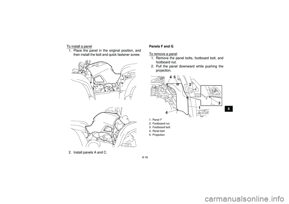
To install a panel
1. Place the panel in the original position, and
then install the bolt and quick fastener screw.
2. Install panels A and C. Panels F and G
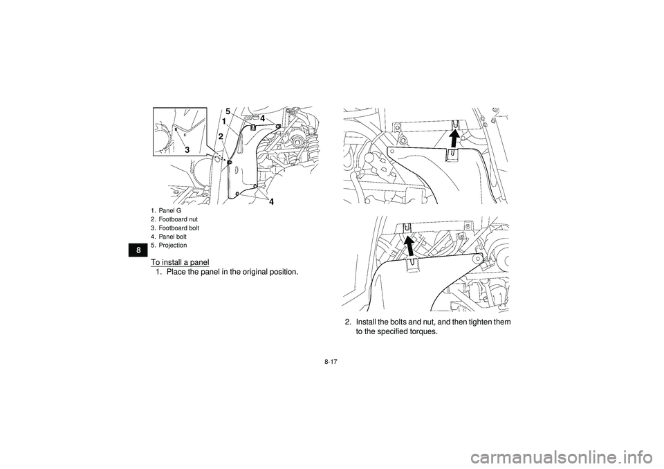
To remove a panel
1. Remove the panel bolts, footboard bolt, and
footboard nut.
2. Pull the panel downward while pushing the projection.1. Panel F
2. Footboard nut
3. Footboard bolt
4. Panel bolt
5. Projection
U1HS60E0.book Page 16 Tuesday, April 26, 2011 7:53 PM
Page 106 of 172
8-17
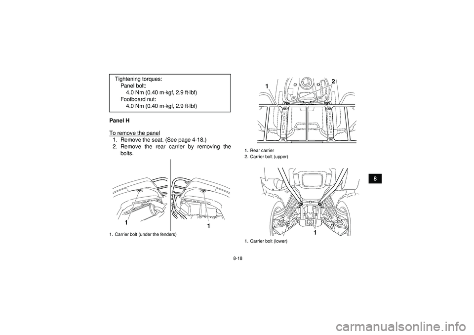
8To install a panel
1. Place the panel in the original position.
2. Install the bolts and nut, and then tighten themto the specified torques.1. Panel G
2. Footboard nut
3. Footboard bolt
4. Panel bolt
5. ProjectionU1HS60E0.book Page 17 Tuesday, April 26, 2011 7:53 PM
Page 107 of 172
8-18
8
Panel H
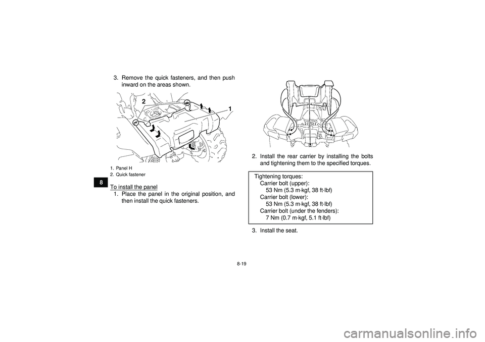
To remove the panel
1. Remove the seat. (See page 4-18.)
2. Remove the rear carrier by removing the
bolts.
Tightening torques:
Panel bolt:4.0 Nm (0.40 m· kgf, 2.9 ft·lbf)
Footboard nut: 4.0 Nm (0.40 m· kgf, 2.9 ft·lbf)1. Carrier bolt (under the fenders)
1. Rear carrier
2. Carrier bolt (upper)
1. Carrier bolt (lower)
U1HS60E0.book Page 18 Tuesday, April 26, 2011 7:53 PM
Page 108 of 172
8-19
83. Remove the quick fasteners, and then push
inward on the areas shown.
To install the panel
1. Place the panel in the original position, and then install the quick fasteners. 2. Install the rear carrier by installing the bolts
and tightening them to the specified torques.
3. Install the seat.1. Panel H
2. Quick fastener
2
1
Tightening torques: Carrier bolt (upper):53 Nm (5.3 m ·kgf, 38 ft· lbf)
Carrier bolt (lower): 53 Nm (5.3 m ·kgf, 38 ft· lbf)
Carrier bolt (under the fenders): 7 Nm (0.7 m ·kgf, 5.1 ft· lbf)
U1HS60E0.book Page 19 Tuesday, April 26, 2011 7:53 PM
Page 109 of 172
8-20
8
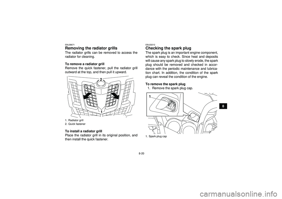
EBU28671Removing the radiator grills The radiator grills can be removed to access the
radiator for cleaning.
To remove a radiator grill
Remove the quick fastener, pull the radiator grill
outward at the top, and then pull it upward.
To install a radiator grill
Place the radiator grill in its original position, and
then install the quick fastener.
EBU23213Checking the spark plug The spark plug is an important engine component,
which is easy to check. Since heat and deposits
will cause any spark plug to slowly erode, the spark
plug should be removed and checked in accor-
dance with the periodic maintenance and lubrica-
tion chart. In addition, the condition of the spark
plug can reveal the condition of the engine.
To remove the spark plug1. Remove the spark plug cap.
1. Radiator grill
2. Quick fastener
21
1. Spark plug cap1
U1HS60E0.book Page 20 Tuesday, April 26, 2011 7:53 PM
Page 110 of 172
8-21
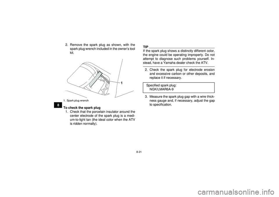
82. Remove the spark plug as shown, with the
spark plug wrench included in the owner ’s tool
kit.
To check the spark plug 1. Check that the porcelain insulator around the center electrode of the spark plug is a medi-
um-to-light tan (the ideal color when the ATV
is ridden normally).
TIPIf the spark plug shows a distinctly different color,
the engine could be operating improperly. Do not
attempt to diagnose such problems yourself. In-
stead, have a Yamaha dealer check the ATV.2. Check the spark plug for electrode erosionand excessive carbon or other deposits, and
replace it if necessary.
3. Measure the spark plug gap with a wire thick- ness gauge and, if necessary, adjust the gap
to specification.
1. Spark plug wrench
Specified spark plug:NGK/LMAR6A-9
U1HS60E0.book Page 21 Tuesday, April 26, 2011 7:53 PM
Trending: odometer, load capacity, fuel filter, change time, oil change, gas type, recommended oil
