torque YAMAHA GRIZZLY 550 2015 User Guide
[x] Cancel search | Manufacturer: YAMAHA, Model Year: 2015, Model line: GRIZZLY 550, Model: YAMAHA GRIZZLY 550 2015Pages: 174, PDF Size: 4.2 MB
Page 122 of 174
8-30
85. Install the oil filler bolt and its gasket, and then
tighten the bolt to the specified torque.
To change the differential gear oil 1. Place the ATV on a level surface.
2. Place an oil pan under the differential gear case to collect the used oil.
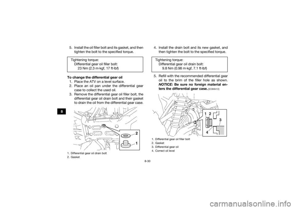
3. Remove the differential gear oil filler bolt, the differential gear oil drain bolt and their gasket
to drain the oil from the differential gear case. 4. Install the drain bolt and its new gasket, and
then tighten the bolt to the specified torque.
5. Refill with the recommended differential gear oil to the brim of the filler hole as shown.
NOTICE: Be sure no foreign material en-
ters the differential gear case.
[ECB00412]
Tightening torque: Differential gear oil filler bolt:23 Nm (2.3 m·kgf, 17 ft·lbf)1. Differential gear oil drain bolt
2. Gasket
12
Tightening torque:Differential gear oil drain bolt:9.8 Nm (0.98 m·kgf, 7.1 ft·lbf)1. Differential gear oil filler bolt
2. Gasket
3. Differential gear oil
4. Correct oil level
1
2
3
4
U2LB61E0.book Page 30 Friday, February 21, 2014 3:03 PM
Page 123 of 174
8-31
8
6. Check the oil filler bolt gasket for damage,
and replace it if necessary.
7. Install the oil filler bolt and its gasket, and then tighten the bolt to the specified torque.
8. Check the differential gear case for oil leak- age. If oil is leaking, check for the cause.
EBU23471CoolantThe coolant level should be checked before each
ride. In addition, the coolant must be changed at
the intervals specified in the periodic maintenance
and lubrication chart.EBU27127To check the coolant level1. Place the ATV on a level surface.
TIPThe coolant level must be checked on a cold en-
gine since the level varies with engine tempera-
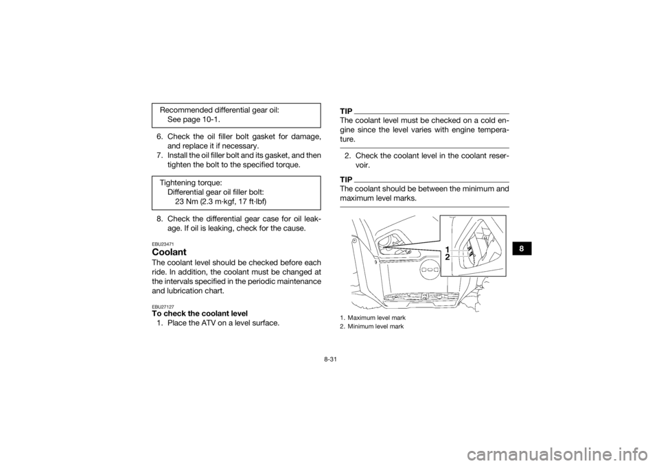
ture. 2. Check the coolant level in the coolant reser- voir.TIPThe coolant should be between the minimum and
maximum level marks.
Recommended differential gear oil:See page 10-1.
Tightening torque: Differential gear oil filler bolt:23 Nm (2.3 m·kgf, 17 ft·lbf)
1. Maximum level mark
2. Minimum level mark
U2LB61E0.book Page 31 Friday, February 21, 2014 3:03 PM
Page 127 of 174
8-35
8
9. After draining the coolant, thoroughly flush
the cooling system with clean tap water.
10. Install the coolant drain bolt and its new gas- ket, and then tighten the bolt to the specified
torque.
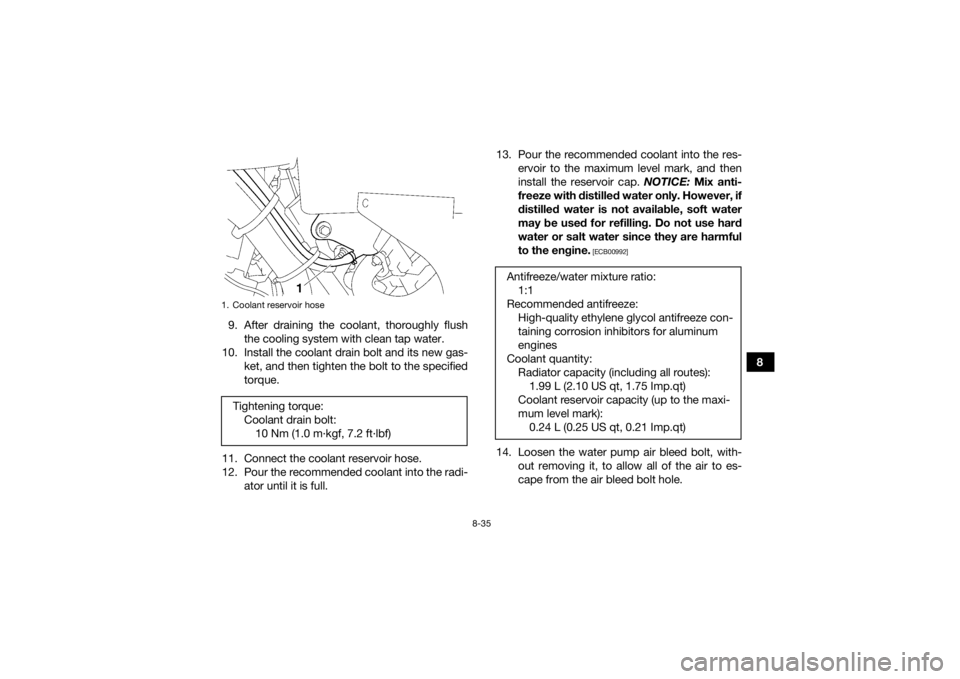
11. Connect the coolant reservoir hose.
12. Pour the recommended coolant into the radi- ator until it is full. 13. Pour the recommended coolant into the res-
ervoir to the maximum level mark, and then
install the reservoir cap. NOTICE: Mix anti-
freeze with distilled water only. However, if
distilled water is not available, soft water
may be used for refilling. Do not use hard
water or salt water since they are harmful
to the engine.
[ECB00992]
14. Loosen the water pump air bleed bolt, with- out removing it, to allow all of the air to es-
cape from the air bleed bolt hole.
1. Coolant reservoir hoseTightening torque:Coolant drain bolt:10 Nm (1.0 m·kgf, 7.2 ft·lbf)
Antifreeze/water mixture ratio: 1:1
Recommended antifreeze: High-quality ethylene glycol antifreeze con-
taining corrosion inhibitors for aluminum
engines
Coolant quantity: Radiator capacity (including all routes):1.99 L (2.10 US qt, 1.75 Imp.qt)
Coolant reservoir capacity (up to the maxi-
mum level mark): 0.24 L (0.25 US qt, 0.21 Imp.qt)
U2LB61E0.book Page 35 Friday, February 21, 2014 3:03 PM
Page 128 of 174
8-36
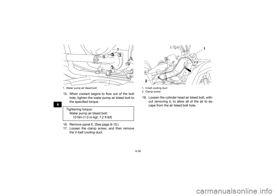
815. When coolant begins to flow out of the bolt
hole, tighten the water pump air bleed bolt to
the specified torque.
16. Remove panel E. (See page 8-10.)
17. Loosen the clamp screw, and then remove the V-belt cooling duct. 18. Loosen the cylinder head air bleed bolt, with-
out removing it, to allow all of the air to es-
cape from the air bleed bolt hole.
1. Water pump air bleed boltTightening torque:Water pump air bleed bolt:10 Nm (1.0 m·kgf, 7.2 ft·lbf)
1
1. V-belt cooling duct
2. Clamp screw
U2LB61E0.book Page 36 Friday, February 21, 2014 3:03 PM
Page 129 of 174
8-37
8
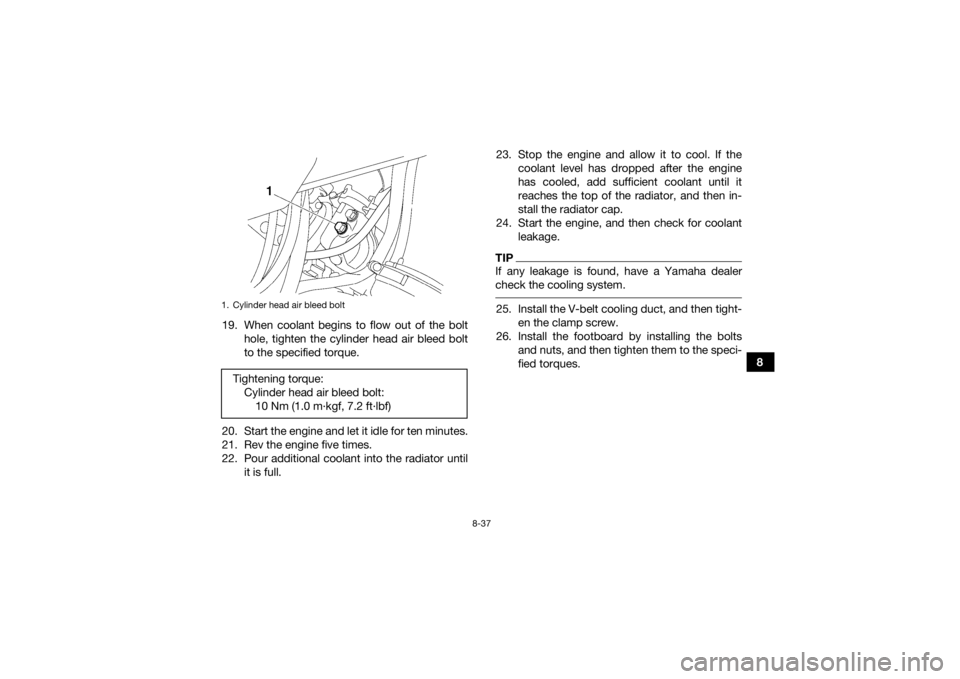
19. When coolant begins to flow out of the bolt
hole, tighten the cylinder head air bleed bolt
to the specified torque.
20. Start the engine and let it idle for ten minutes.
21. Rev the engine five times.
22. Pour additional coolant into the radiator until it is full. 23. Stop the engine and allow it to cool. If the
coolant level has dropped after the engine
has cooled, add sufficient coolant until it
reaches the top of the radiator, and then in-
stall the radiator cap.
24. Start the engine, and then check for coolant leakage.
TIPIf any leakage is found, have a Yamaha dealer
check the cooling system. 25. Install the V-belt cooling duct, and then tight-en the clamp screw.
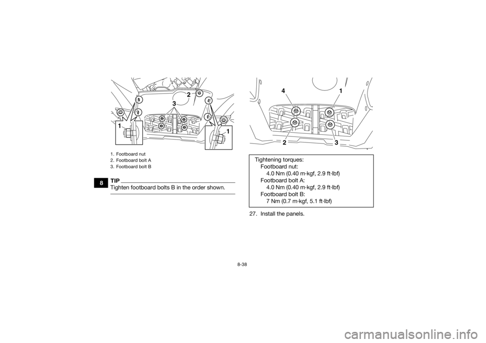
26. Install the footboard by installing the bolts and nuts, and then tighten them to the speci-
fied torques.
1. Cylinder head air bleed boltTightening torque:Cylinder head air bleed bolt:10 Nm (1.0 m·kgf, 7.2 ft·lbf)
U2LB61E0.book Page 37 Friday, February 21, 2014 3:03 PM
Page 130 of 174
8-38
8
TIPTighten footboard bolts B in the order shown.
27. Install the panels.
1. Footboard nut
2. Footboard bolt A
3. Footboard bolt B
3
1
2
1
Tightening torques:Footboard nut:4.0 Nm (0.40 m·kgf, 2.9 ft·lbf)
Footboard bolt A: 4.0 Nm (0.40 m·kgf, 2.9 ft·lbf)
Footboard bolt B: 7 Nm (0.7 m·kgf, 5.1 ft·lbf)
4
1
2
3
U2LB61E0.book Page 38 Friday, February 21, 2014 3:03 PM
Page 135 of 174
8-43
8
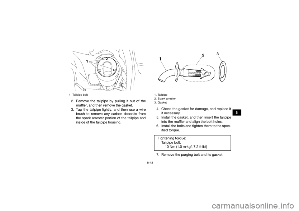
2. Remove the tailpipe by pulling it out of the
muffler, and then remove the gasket.
3. Tap the tailpipe lightly, and then use a wire brush to remove any carbon deposits from
the spark arrester portion of the tailpipe and
inside of the tailpipe housing. 4. Check the gasket for damage, and replace it
if necessary.
5. Install the gasket, and then insert the tailpipe into the muffler and align the bolt holes.
6. Install the bolts and tighten them to the spec- ified torque.
7. Remove the purging bolt and its gasket.
1. Tailpipe bolt
1. Tailpipe
2. Spark arrester
3. GasketTightening torque: Tailpipe bolt:10 Nm (1.0 m·kgf, 7.2 ft·lbf)
U2LB61E0.book Page 43 Friday, February 21, 2014 3:03 PM
Page 136 of 174
8-44
88. Start the engine and rev it up approximately
twenty times while momentarily creating ex-
haust system back pressure by blocking the
end of the muffler with a shop towel.
9. Stop the engine and allow the exhaust pipe to cool.
10. Check the gasket for damage, and replace it if necessary.
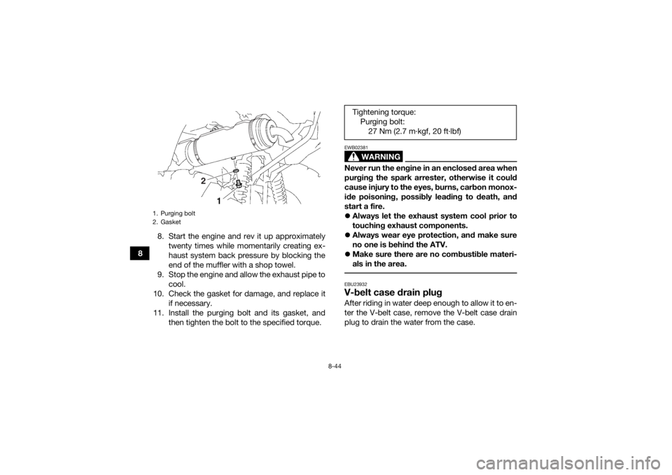
11. Install the purging bolt and its gasket, and then tighten the bolt to the specified torque.
WARNING
EWB02381Never run the engine in an enclosed area when
purging the spark arrester, otherwise it could
cause injury to the eyes, burns, carbon monox-
ide poisoning, possibly leading to death, and
start a fire.
Always let the exhaust system cool prior to
touching exhaust components.
Always wear eye protection, and make sure
no one is behind the ATV.
Make sure there are no combustible materi-
als in the area. EBU23932V-belt case drain plugAfter riding in water deep enough to allow it to en-
ter the V-belt case, remove the V-belt case drain
plug to drain the water from the case.
1. Purging bolt
2. Gasket
2
Tightening torque:
Purging bolt:27 Nm (2.7 m·kgf, 20 ft·lbf)
U2LB61E0.book Page 44 Friday, February 21, 2014 3:03 PM
Page 151 of 174
8-59
8
4. Install the front carrier by installing the bolts
and tightening them to the specified torques.
5. Install the panel.
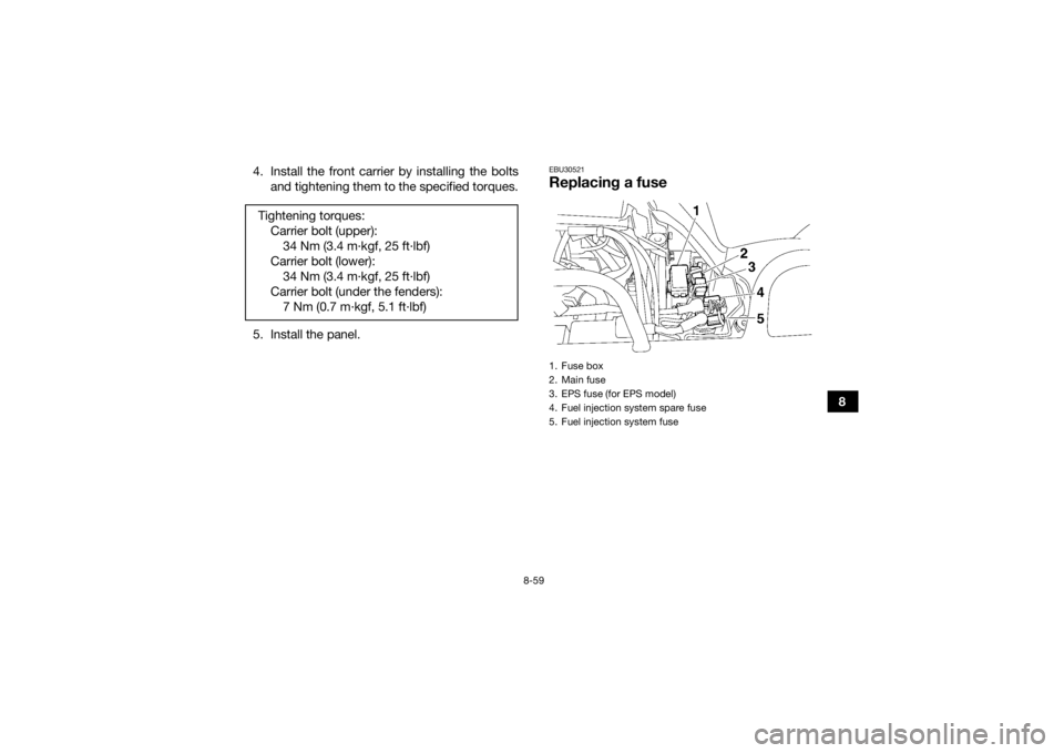
EBU30521Replacing a fuse
Tightening torques: Carrier bolt (upper):34 Nm (3.4 m·kgf, 25 ft·lbf)
Carrier bolt (lower): 34 Nm (3.4 m·kgf, 25 ft·lbf)
Carrier bolt (under the fenders): 7 Nm (0.7 m·kgf, 5.1 ft·lbf)
1. Fuse box
2. Main fuse
3. EPS fuse (for EPS model)
4. Fuel injection system spare fuse
5. Fuel injection system fuse
U2LB61E0.book Page 59 Friday, February 21, 2014 3:03 PM
Page 157 of 174
8-65
8
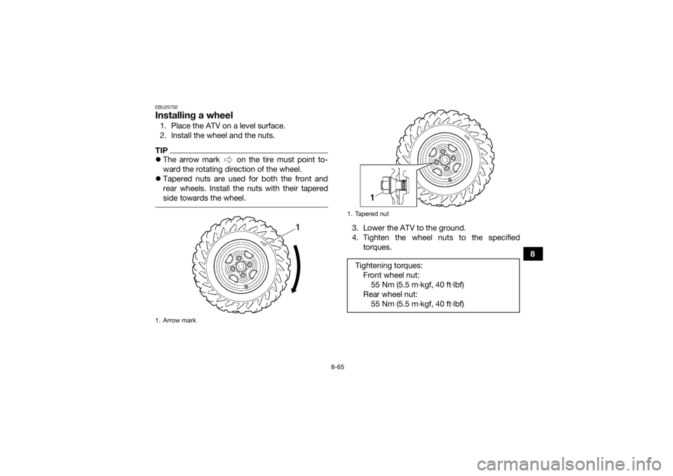
EBU25702Installing a wheel1. Place the ATV on a level surface.
2. Install the wheel and the nuts.TIPThe arrow mark on the tire must point to-
ward the rotating direction of the wheel.
Tapered nuts are used for both the front and
rear wheels. Install the nuts with their tapered
side towards the wheel.
3. Lower the ATV to the ground.
4. Tighten the wheel nuts to the specified
torques.
1. Arrow mark
1
1. Tapered nutTightening torques:Front wheel nut:55 Nm (5.5 m·kgf, 40 ft·lbf)
Rear wheel nut: 55 Nm (5.5 m·kgf, 40 ft·lbf)
U2LB61E0.book Page 65 Friday, February 21, 2014 3:03 PM