engine YAMAHA GRIZZLY 660 2005 Workshop Manual
[x] Cancel search | Manufacturer: YAMAHA, Model Year: 2005, Model line: GRIZZLY 660, Model: YAMAHA GRIZZLY 660 2005Pages: 456, PDF Size: 18.27 MB
Page 348 of 456
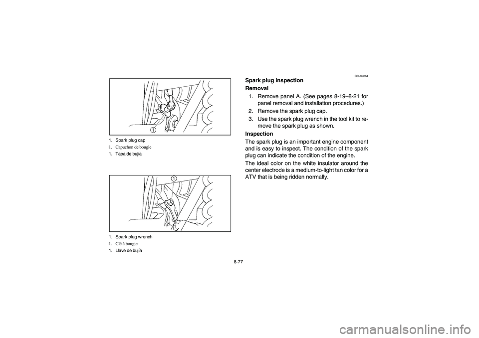
8-77 1. Spark plug cap
1. Capuchon de bougie
1. Tapa de bujía
1. Spark plug wrench
1. Clé à bougie
1. Llave de bujía
EBU00864
Spark plug inspection
Removal
1. Remove panel A. (See pages 8-19–8-21 for
panel removal and installation procedures.)
2. Remove the spark plug cap.
3. Use the spark plug wrench in the tool kit to re-
move the spark plug as shown.
Inspection
The spark plug is an important engine component
and is easy to inspect. The condition of the spark
plug can indicate the condition of the engine.
The ideal color on the white insulator around the
center electrode is a medium-to-light tan color for a
ATV that is being ridden normally.
U5KM63.book Page 77 Monday, March 15, 2004 11:44 AM
Page 358 of 456
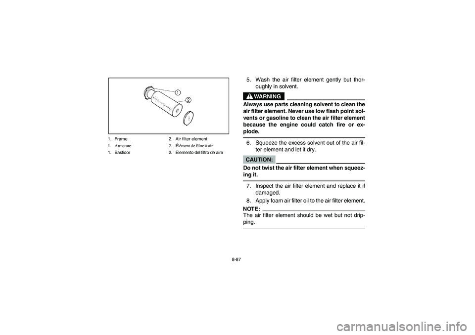
8-87 1. Frame 2. Air filter element
1. Armature 2.Élément de filtre à air
1. Bastidor 2. Elemento del filtro de aire
5. Wash the air filter element gently but thor-
oughly in solvent.
WARNING
_ Always use parts cleaning solvent to clean the
air filter element. Never use low flash point sol-
vents or gasoline to clean the air filter element
because the engine could catch fire or ex-
plode. _6. Squeeze the excess solvent out of the air fil-
ter element and let it dry.CAUTION:_ Do not twist the air filter element when squeez-
ing it. _7. Inspect the air filter element and replace it if
damaged.
8. Apply foam air filter oil to the air filter element.NOTE:_ The air filter element should be wet but not drip-
ping. _
U5KM63.book Page 87 Monday, March 15, 2004 11:44 AM
Page 360 of 456
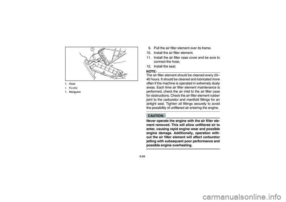
8-89 1. Hose
1. Flexible
1. Manguera
9. Pull the air filter element over its frame.
10. Install the air filter element.
11. Install the air filter case cover and be sure to
connect the hose.
12. Install the seat.NOTE:_ The air filter element should be cleaned every 20–
40 hours. It should be cleaned and lubricated more
often if the machine is operated in extremely dusty
areas. Each time air filter element maintenance is
performed, check the air inlet to the air filter case
for obstructions. Check the air filter element rubber
joint to the carburetor and manifold fittings for an
airtight seal. Tighten all fittings securely to avoid
the possibility of unfiltered air entering the engine. _CAUTION:_ Never operate the engine with the air filter ele-
ment removed. This will allow unfiltered air to
enter, causing rapid engine wear and possible
engine damage. Additionally, operation with-
out the air filter element will affect carburetor
jetting with subsequent poor performance and
possible engine overheating. _
U5KM63.book Page 89 Monday, March 15, 2004 11:44 AM
Page 362 of 456

8-91 1. V-belt cooling duct check hose (Left side)
1. Flexible de contrôle du conduit de refroidissement de la courroie
trapézoïdale (côté gauche)
1. Manguera de comprobación del conducto de enfriamiento de
la correa trapezoidal (Lado izquierdo)
1. V-belt case drain plug
1. Boulon de vidange du carter de la courroie trapézoïdale
1. Tapón de drenaje de la caja de la correa trapezoidal
EBU06411
V-belt cooling duct check hose
If dust or water collects in the V-belt cooling duct
check hose, remove the hose and clean it.
EBU08741
V-belt case drain plug
After riding in water deep enough to allow it to en-
ter the V-belt case, remove this plug to drain the
water from the case.NOTE:_ If water drains from the V-belt case after removing
the plug, have a Yamaha dealer inspect the ATV
as the water may affect other engine parts. _
U5KM63.book Page 91 Monday, March 15, 2004 11:44 AM
Page 364 of 456
8-93
EBU00296
Carburetor adjustment
The carburetor is a vital part of the engine and re-
quires very sophisticated adjustment. Most adjust-
ing should be left to a Yamaha dealer who has the
professional knowledge and experience to do so.
However, the idling speed may be performed by
the owner as a part of the usual maintenance rou-
tine.CAUTION:
The carburetor was set at the Yamaha factory
after many tests. If the settings are disturbed
by someone without sufficient technical
knowledge, poor engine performance and
damage may result.
U5KM63.book Page 93 Monday, March 15, 2004 11:44 AM
Page 366 of 456
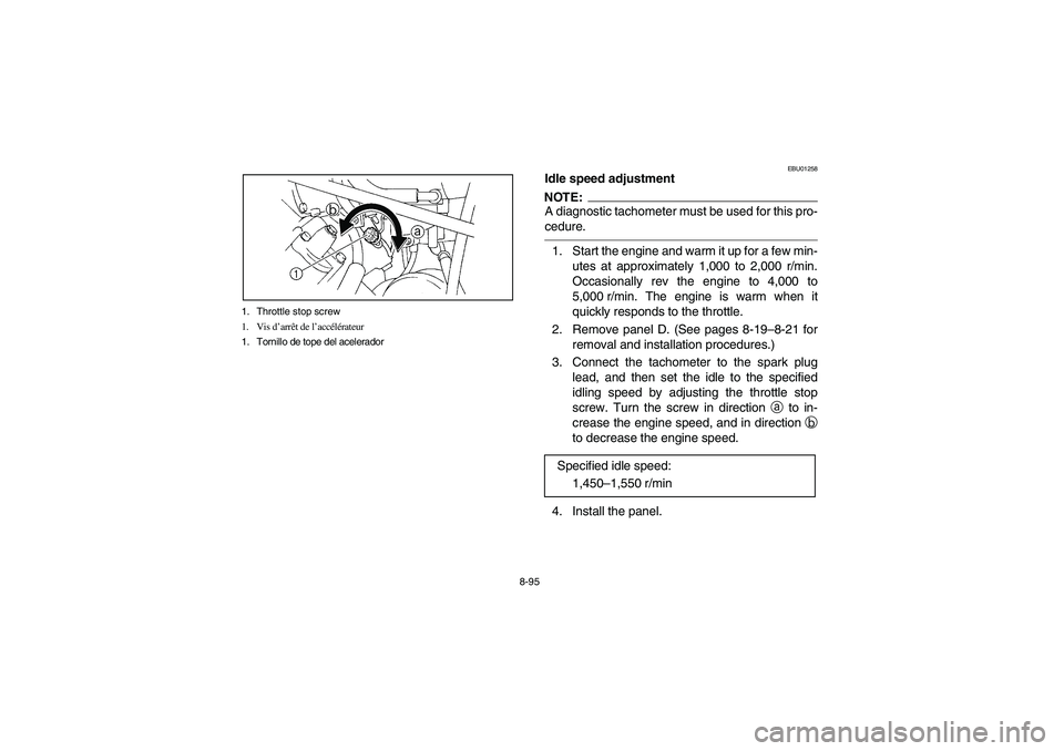
8-95 1. Throttle stop screw
1. Vis d’arrêt de l’accélérateur
1. Tornillo de tope del acelerador
EBU01258
Idle speed adjustmentNOTE:_ A diagnostic tachometer must be used for this pro-
cedure. _1. Start the engine and warm it up for a few min-
utes at approximately 1,000 to 2,000 r/min.
Occasionally rev the engine to 4,000 to
5,000 r/min. The engine is warm when it
quickly responds to the throttle.
2. Remove panel D. (See pages 8-19–8-21 for
removal and installation procedures.)
3. Connect the tachometer to the spark plug
lead, and then set the idle to the specified
idling speed by adjusting the throttle stop
screw. Turn the screw in direction
a to in-
crease the engine speed, and in direction
b
to decrease the engine speed.
4. Install the panel.Specified idle speed:
1,450–1,550 r/min
U5KM63.book Page 95 Monday, March 15, 2004 11:44 AM
Page 368 of 456
8-97
EBU00303
Valve clearance adjustment
The correct valve clearance changes with use, re-
sulting in improper fuel/air supply or engine noise.
To prevent this, the valve clearance must be ad-
justed regularly. This adjustment however, should
be left to a professional Yamaha service techni-
cian.
EBU03050
Select lever safety system cable adjustment
The select lever safety system cable stretches
with use, resulting in improper function. To prevent
this, the cable must be adjusted regularly. This ad-
justment, however, should be left to a Yamaha
dealer.
U5KM63.book Page 97 Monday, March 15, 2004 11:44 AM
Page 370 of 456
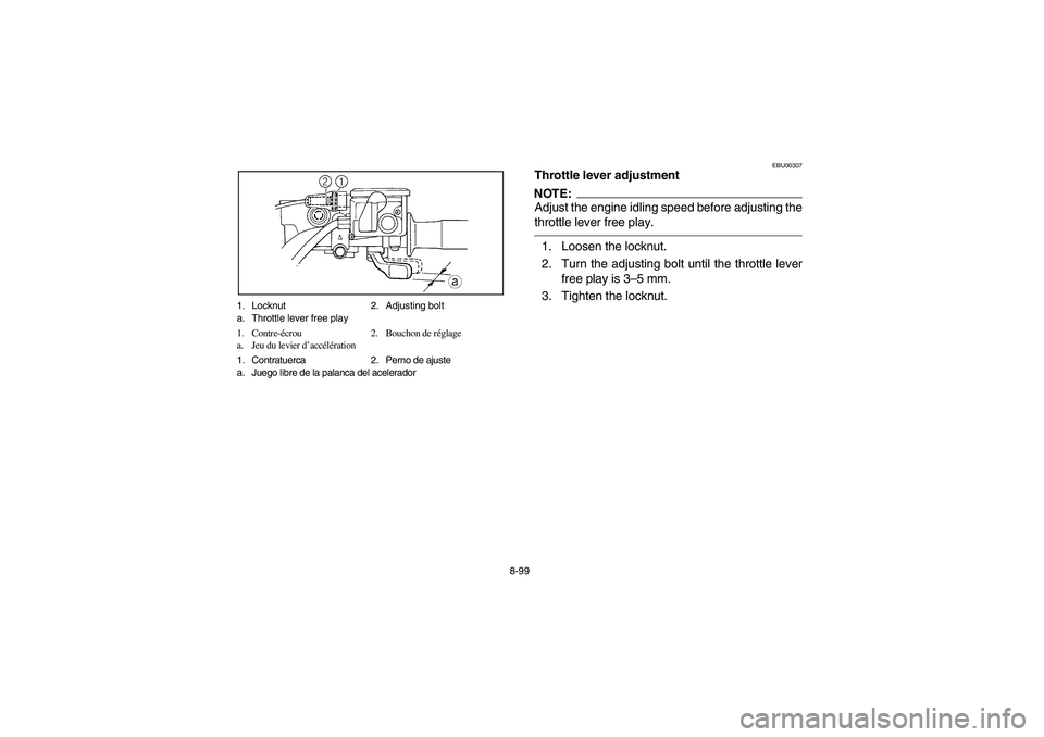
8-99 1. Locknut 2. Adjusting bolt
a. Throttle lever free play
1. Contre-écrou 2. Bouchon de réglage
a. Jeu du levier d’accélération
1. Contratuerca 2. Perno de ajuste
a. Juego libre de la palanca del acelerador
EBU00307
Throttle lever adjustmentNOTE:Adjust the engine idling speed before adjusting the
throttle lever free play.1. Loosen the locknut.
2. Turn the adjusting bolt until the throttle lever
free play is 3–5 mm.
3. Tighten the locknut.
U5KM63.book Page 99 Monday, March 15, 2004 11:44 AM
Page 388 of 456
8-117
EBU00570
Cable inspection and lubrication
WARNING
Inspect cables frequently and replace if dam-
aged. Corrosion can result when the outer cov-
ering of control cables becomes damaged.
Cables can also become frayed or kinked. Op-
eration of controls could be restricted, which
could cause an accident or injury.Lubricate the inner cables and the cable ends. If
the cables do not operate smoothly, ask a Yamaha
dealer to replace them.
Recommended lubricant:
Engine oil
U5KM63.book Page 117 Monday, March 15, 2004 11:44 AM
Page 418 of 456

8-147
EBU00724Troubleshooting chart
Starting problems or poor engine performance1. Fuel
Check if there is fuel
in the fuel tank.There is fuel.Turn the fuel cock
lever to “OFF”.No fuel.Fuel cock is
clogged.
Clean the
fuel cock. Some fuel.Turn the fuel cock
lever to “RES”.Restart the engine.
No fuel.Supply fuel.
2. Compression
Use the electric
starter to see if
there is compression.There is compression.
Compression normal.
No compression.Ask a Yamaha dealer to
inspect.
3. Ignition
Remove the
spark plug and
check the electrodes.WetWipe clean with dry cloth.
DryAttach spark plug cap and
ground to chassis.Use the
electric starter.Spark is good.Ignition system is
normal.
Spark is weak.
Adjust the spark plug gap
or replace the spark plug. No spark.
Ask a Yamaha dealer to
inspect. 4. Battery
Use the electric starter.Engine turns over
quickly.Battery is good.
Engine turns over
slowly.Check the battery lead connections,
and charge the battery if necessary.Check the
fuel flow.
Turn the fuel cock
lever to “ON”.
Remove the fuel hose
from the fuel cock.
U5KM63.book Page 147 Monday, March 15, 2004 11:44 AM