YAMAHA GRIZZLY 700 2013 Owners Manual
GRIZZLY 700 2013
YAMAHA
YAMAHA
https://www.carmanualsonline.info/img/51/50464/w960_50464-0.png
YAMAHA GRIZZLY 700 2013 Owners Manual
Trending: ignition, tire pressure, maintenance, oil dipstick, high beam, parking brake, oil type
Page 101 of 174
8-10
8
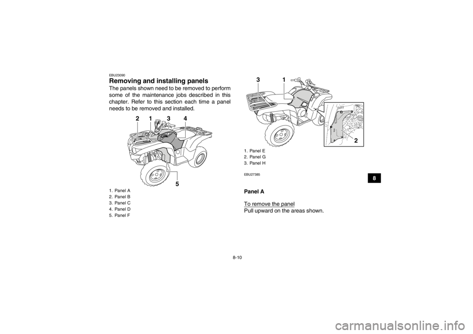
EBU23090Removing and installing panels The panels shown need to be removed to perform
some of the maintenance jobs described in this
chapter. Refer to this section each time a panel
needs to be removed and installed.
EBU27385Panel A
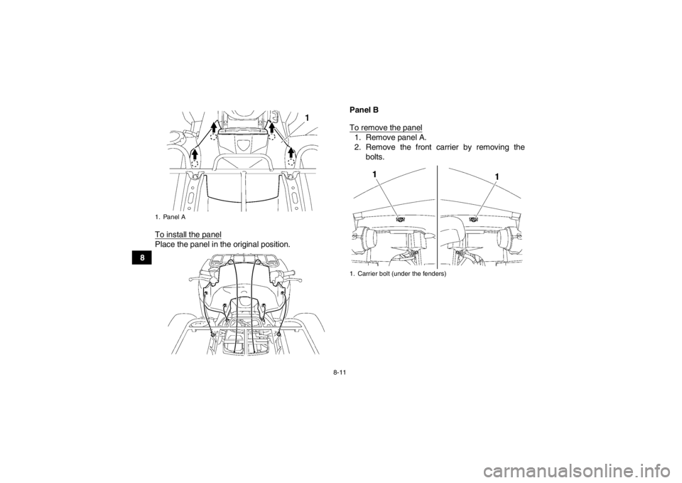
To remove the panelPull upward on the areas shown.
1. Panel A
2. Panel B
3. Panel C
4. Panel D
5. Panel F
1
2
3
5
4
1. Panel E
2. Panel G
3. Panel H
1
3
2
U1HP61E0.book Page 10 Thursday, April 5, 2012 3:33 PM
Page 102 of 174
8-11
8To install the panel
Place the panel in the original position. Panel B
To remove the panel
1. Remove panel A.
2. Remove the front carrier by removing the
bolts.
1. Panel A
1. Carrier bolt (under the fenders)
U1HP61E0.book Page 11 Thursday, April 5, 2012 3:33 PM
Page 103 of 174
8-12
8
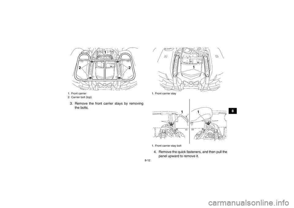
3. Remove the front carrier stays by removing
the bolts.
4. Remove the quick fasteners, and then pull thepanel upward to remove it.
1. Front carrier
2. Carrier bolt (top)
1. Front carrier stay
1. Front carrier stay bolt
U1HP61E0.book Page 12 Thursday, April 5, 2012 3:33 PM
Page 104 of 174
8-13
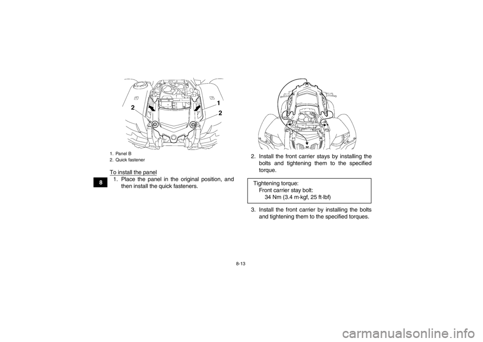
8To install the panel
1. Place the panel in the original position, and
then install the quick fasteners. 2. Install the front carrier stays by installing the
bolts and tightening them to the specified
torque.
3. Install the front carrier by installing the bolts and tightening them to the specified torques.1. Panel B
2. Quick fastener
Tightening torque:Front carrier stay bolt:34 Nm (3.4 m·kgf, 25 ft·lbf)
U1HP61E0.book Page 13 Thursday, April 5, 2012 3:33 PM
Page 105 of 174
8-14
8
4. Install panel A.
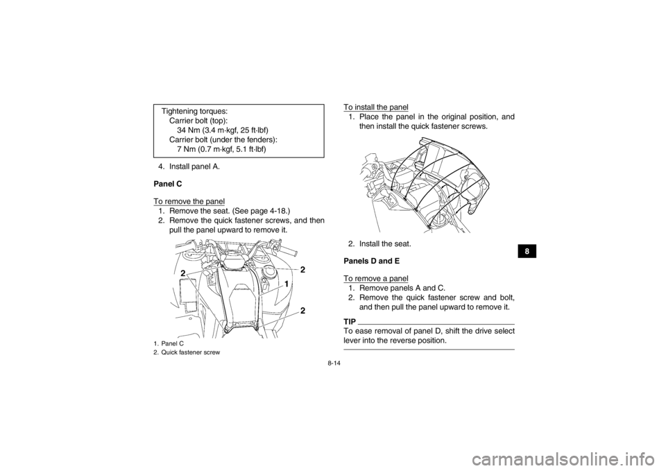
Panel C
To remove the panel
1. Remove the seat. (See page 4-18.)
2. Remove the quick fastener screws, and then pull the panel upward to remove it. To install the panel
1. Place the panel in the original position, and
then install the quick fastener screws.
2. Install the seat.
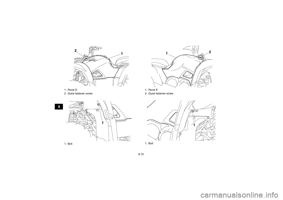
Panels D and E
To remove a panel1. Remove panels A and C.
2. Remove the quick fastener screw and bolt, and then pull the panel upward to remove it.TIPTo ease removal of panel D, shift the drive select
lever into the reverse position.
Tightening torques:Carrier bolt (top):34 Nm (3.4 m·kgf, 25 ft·lbf)
Carrier bolt (under the fenders): 7 Nm (0.7 m·kgf, 5.1 ft·lbf)1. Panel C
2. Quick fastener screwU1HP61E0.book Page 14 Thursday, April 5, 2012 3:33 PM
Page 106 of 174
8-15
8
1. Panel D
2. Quick fastener screw
1. Bolt
1. Panel E
2. Quick fastener screw
1. Bolt
U1HP61E0.book Page 15 Thursday, April 5, 2012 3:33 PM
Page 107 of 174
8-16
8
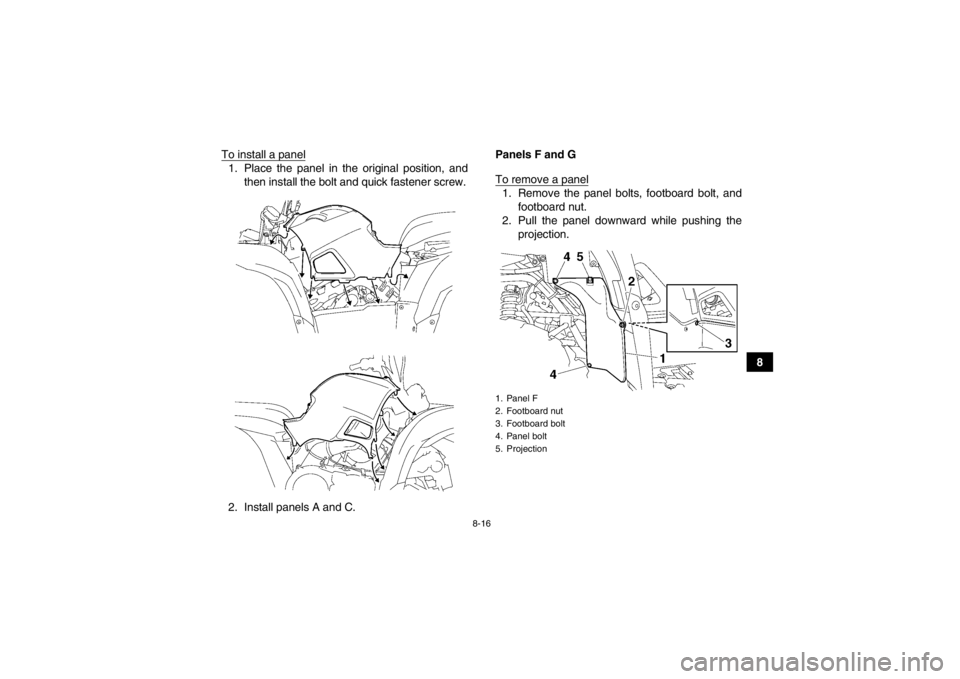
To install a panel
1. Place the panel in the original position, and
then install the bolt and quick fastener screw.
2. Install panels A and C. Panels F and G
To remove a panel
1. Remove the panel bolts, footboard bolt, and
footboard nut.
2. Pull the panel downward while pushing the projection.1. Panel F
2. Footboard nut
3. Footboard bolt
4. Panel bolt
5. Projection
U1HP61E0.book Page 16 Thursday, April 5, 2012 3:33 PM
Page 108 of 174
8-17
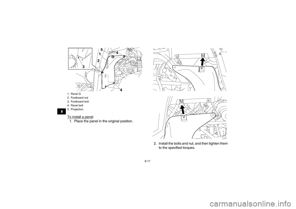
8To install a panel
1. Place the panel in the original position.
2. Install the bolts and nut, and then tighten themto the specified torques.1. Panel G
2. Footboard nut
3. Footboard bolt
4. Panel bolt
5. ProjectionU1HP61E0.book Page 17 Thursday, April 5, 2012 3:33 PM
Page 109 of 174
8-18
8
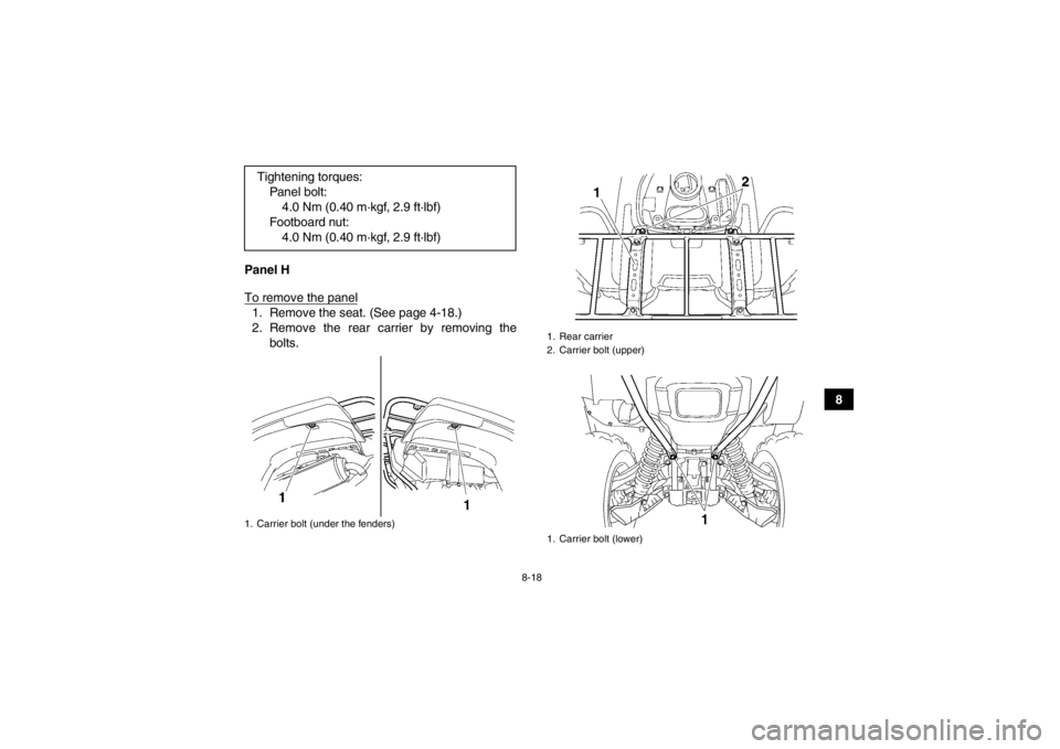
Panel H
To remove the panel
1. Remove the seat. (See page 4-18.)
2. Remove the rear carrier by removing the
bolts.
Tightening torques:
Panel bolt:4.0 Nm (0.40 m·kgf, 2.9 ft·lbf)
Footboard nut: 4.0 Nm (0.40 m·kgf, 2.9 ft·lbf)1. Carrier bolt (under the fenders)
1. Rear carrier
2. Carrier bolt (upper)
1. Carrier bolt (lower)
U1HP61E0.book Page 18 Thursday, April 5, 2012 3:33 PM
Page 110 of 174
8-19
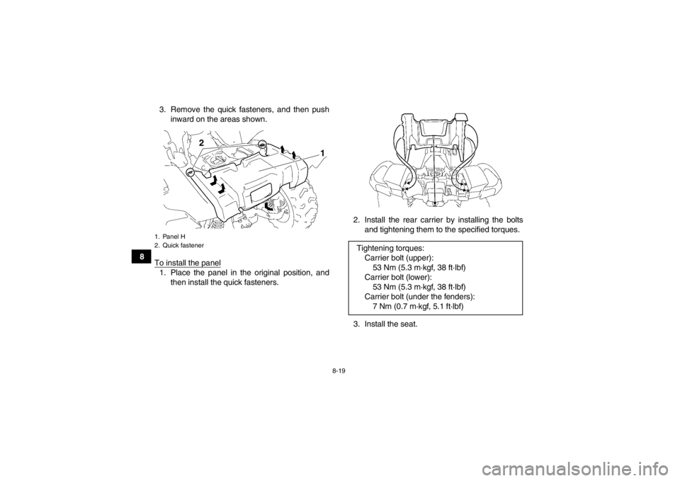
83. Remove the quick fasteners, and then push
inward on the areas shown.
To install the panel
1. Place the panel in the original position, and then install the quick fasteners. 2. Install the rear carrier by installing the bolts
and tightening them to the specified torques.
3. Install the seat.1. Panel H
2. Quick fastener
2
1
Tightening torques: Carrier bolt (upper):53 Nm (5.3 m·kgf, 38 ft·lbf)
Carrier bolt (lower): 53 Nm (5.3 m·kgf, 38 ft·lbf)
Carrier bolt (under the fenders): 7 Nm (0.7 m·kgf, 5.1 ft·lbf)
U1HP61E0.book Page 19 Thursday, April 5, 2012 3:33 PM
Trending: oil pressure, compression ratio, air suspension, check engine light, maintenance, brake pads, oil dipstick
