clock YAMAHA GRIZZLY 700 2013 Owners Manual
[x] Cancel search | Manufacturer: YAMAHA, Model Year: 2013, Model line: GRIZZLY 700, Model: YAMAHA GRIZZLY 700 2013Pages: 174, PDF Size: 4.21 MB
Page 34 of 174
4-5
4
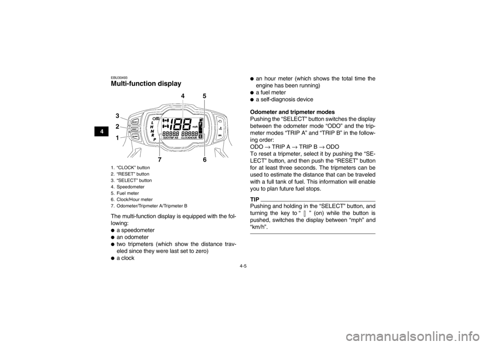
EBU30493Multi-function display The multi-function display is equipped with the fol-
lowing:●a speedometer●an odometer●two tripmeters (which show the distance trav-
eled since they were last set to zero)●a clock
●an hour meter (which shows the total time the
engine has been running)●a fuel meter●a self-diagnosis device
Odometer and tripmeter modes
Pushing the “SELECT” button switches the display
between the odometer mode “ODO” and the trip-
meter modes “TRIP A” and “TRIP B” in the follow-
ing order:
ODO → TRIP A → TRIP B → ODO
To reset a tripmeter, select it by pushing the “SE-
LECT” button, and then push the “RESET” button
for at least three seconds. The tripmeters can be
used to estimate the distance that can be traveled
with a full tank of fuel. This information will enable
you to plan future fuel stops.TIPPushing and holding in the “SELECT” button, and
turning the key to “ ” (on) while the button is
pushed, switches the display between “mph” and
“km/h”.
1. “CLOCK” button
2. “RESET” button
3. “SELECT” button
4. Speedometer
5. Fuel meter
6. Clock/Hour meter
7. Odometer/Tripmeter A/Tripmeter BU1HP61E0.book Page 5 Thursday, April 5, 2012 3:33 PM
Page 35 of 174
4-6
4
Clock mode
Pushing the “CLOCK” button switches the display
between the clock mode “CLOCK” and the hour
meter mode “HOUR” in the following order:
CLOCK
→ HOUR → CLOCK
To set the clock
1. Set the display to the clock mode.
2. Push the “SELECT” button and “RESET” but- ton together for at least three seconds.
3. When the hour digits start flashing, push the “RESET” button to set the hours.
4. Push the “SELECT” button, and the minute digits will start flashing.
5. Push the “RESET” button to set the minutes.
6. Push the “SELECT” button and then release it to start the clock.
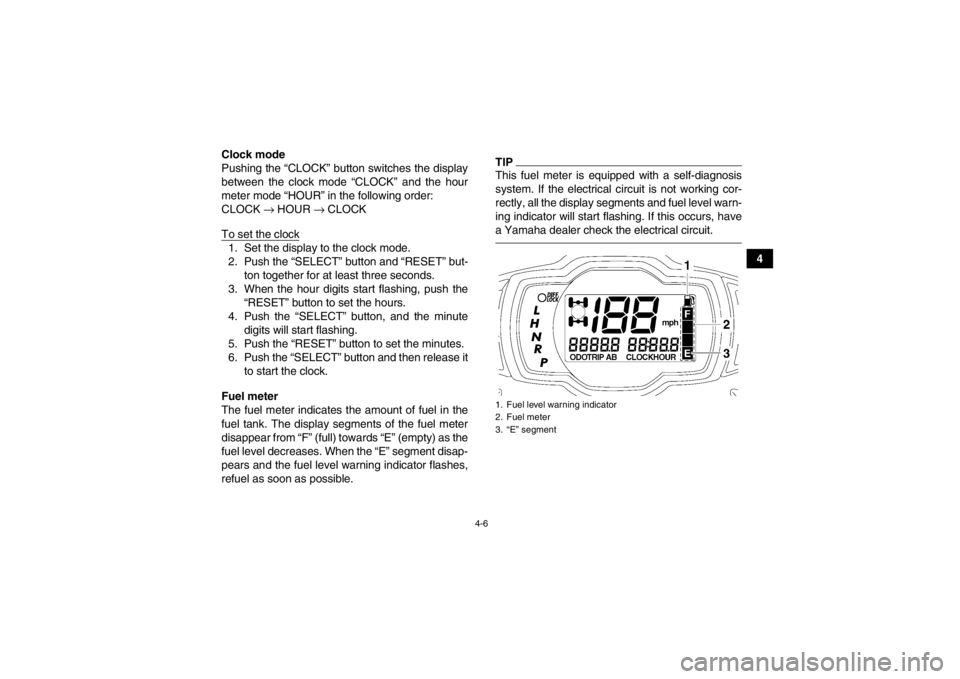
Fuel meter
The fuel meter indicates the amount of fuel in the
fuel tank. The display segments of the fuel meter
disappear from “F” (full) towards “E” (empty) as the
fuel level decreases. When the “E” segment disap-
pears and the fuel level warning indicator flashes,
refuel as soon as possible.
TIPThis fuel meter is equipped with a self-diagnosis
system. If the electrical circuit is not working cor-
rectly, all the display segments and fuel level warn-
ing indicator will start flashing. If this occurs, have
a Yamaha dealer check the electrical circuit.1. Fuel level warning indicator
2. Fuel meter
3. “E” segment
U1HP61E0.book Page 6 Thursday, April 5, 2012 3:33 PM
Page 44 of 174
4-15
4
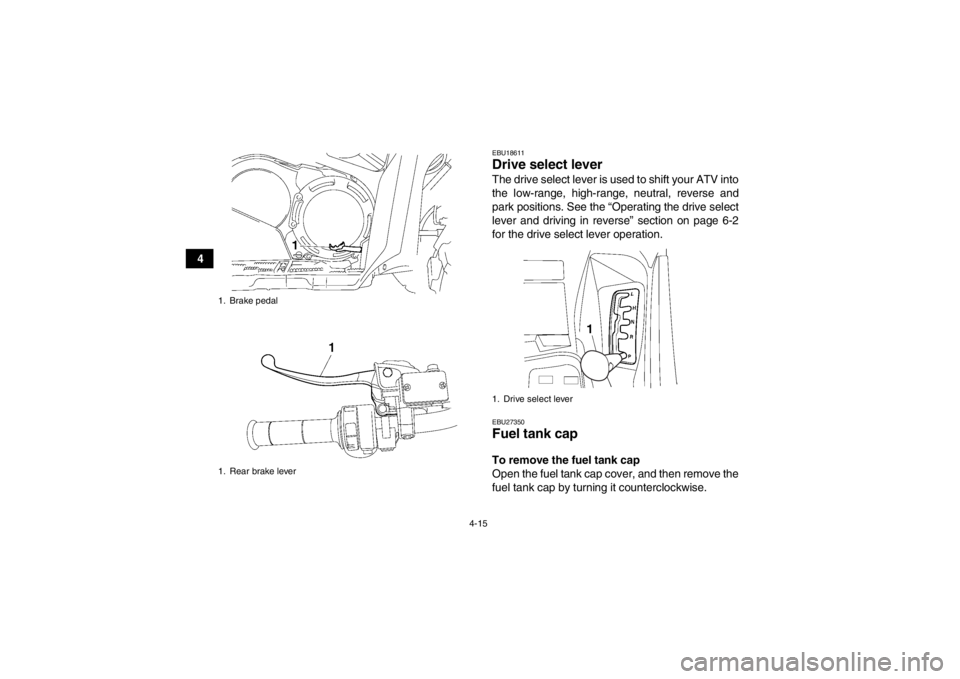
EBU18611Drive select lever The drive select lever is used to shift your ATV into
the low-range, high-range, neutral, reverse and
park positions. See the “Operating the drive select
lever and driving in reverse” section on page 6-2
for the drive select lever operation.EBU27350Fuel tank cap To remove the fuel tank cap
Open the fuel tank cap cover, and then remove the
fuel tank cap by turning it counterclockwise.
1. Brake pedal
1. Rear brake lever
1. Drive select lever
U1HP61E0.book Page 15 Thursday, April 5, 2012 3:33 PM
Page 45 of 174
4-16
4
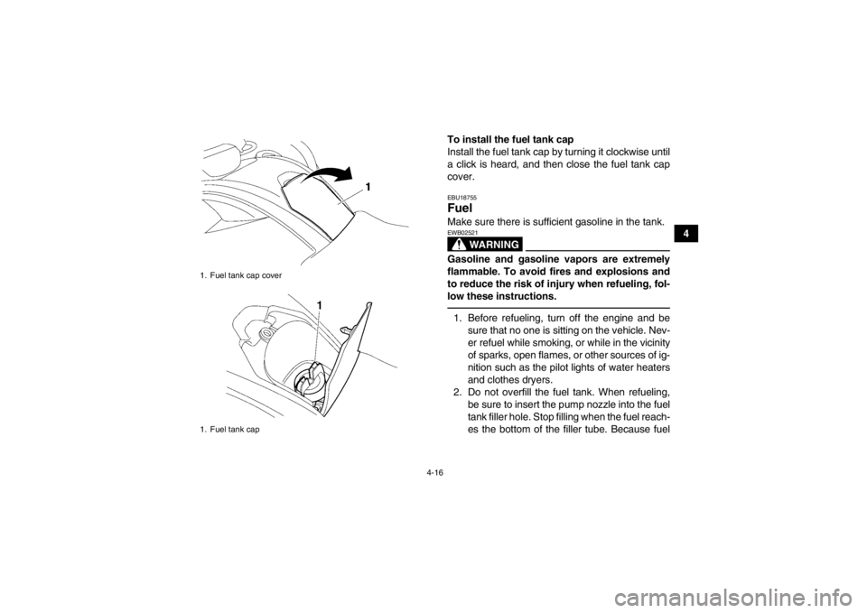
To install the fuel tank cap
Install the fuel tank cap by turning it clockwise until
a click is heard, and then close the fuel tank cap
cover.
EBU18755Fuel Make sure there is sufficient gasoline in the tank.
WARNING
EWB02521Gasoline and gasoline vapors are extremely
flammable. To avoid fires and explosions and
to reduce the risk of injury when refueling, fol-
low these instructions.1. Before refueling, turn off the engine and be
sure that no one is sitting on the vehicle. Nev-
er refuel while smoking, or while in the vicinity
of sparks, open flames, or other sources of ig-
nition such as the pilot lights of water heaters
and clothes dryers.
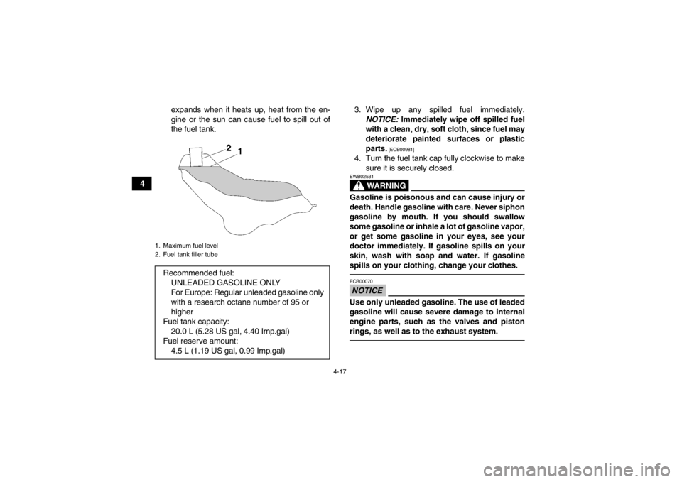
2. Do not overfill the fuel tank. When refueling, be sure to insert the pump nozzle into the fuel
tank filler hole. Stop filling when the fuel reach-
es the bottom of the filler tube. Because fuel
1. Fuel tank cap cover
1. Fuel tank capU1HP61E0.book Page 16 Thursday, April 5, 2012 3:33 PM
Page 46 of 174
4-17
4expands when it heats up, heat from the en-
gine or the sun can cause fuel to spill out of
the fuel tank.
3. Wipe up any spilled fuel immediately.
NOTICE: Immediately wipe off spilled fuel
with a clean, dry, soft cloth, since fuel may
deteriorate painted surfaces or plastic
parts.
[ECB00981]
4. Turn the fuel tank cap fully clockwise to make sure it is securely closed.
WARNING
EWB02531Gasoline is poisonous and can cause injury or
death. Handle gasoline with care. Never siphon
gasoline by mouth. If you should swallow
some gasoline or inhale a lot of gasoline vapor,
or get some gasoline in your eyes, see your
doctor immediately. If gasoline spills on your
skin, wash with soap and water. If gasoline
spills on your clothing, change your clothes.NOTICEECB00070Use only unleaded gasoline. The use of leaded
gasoline will cause severe damage to internal
engine parts, such as the valves and piston
rings, as well as to the exhaust system.
1. Maximum fuel level
2. Fuel tank filler tubeRecommended fuel:UNLEADED GASOLINE ONLY
For Europe: Regular unleaded gasoline only
with a research octane number of 95 or
higher
Fuel tank capacity: 20.0 L (5.28 US gal, 4.40 Imp.gal)
Fuel reserve amount: 4.5 L (1.19 US gal, 0.99 Imp.gal)
U1HP61E0.book Page 17 Thursday, April 5, 2012 3:33 PM
Page 48 of 174
4-19
4
NOTICEECB00830Do not store metal or sharply edged objects,
like tools, in the storage compartments. If they
must be stored, wrap them in appropriate
cushion material to prevent damaging the stor-
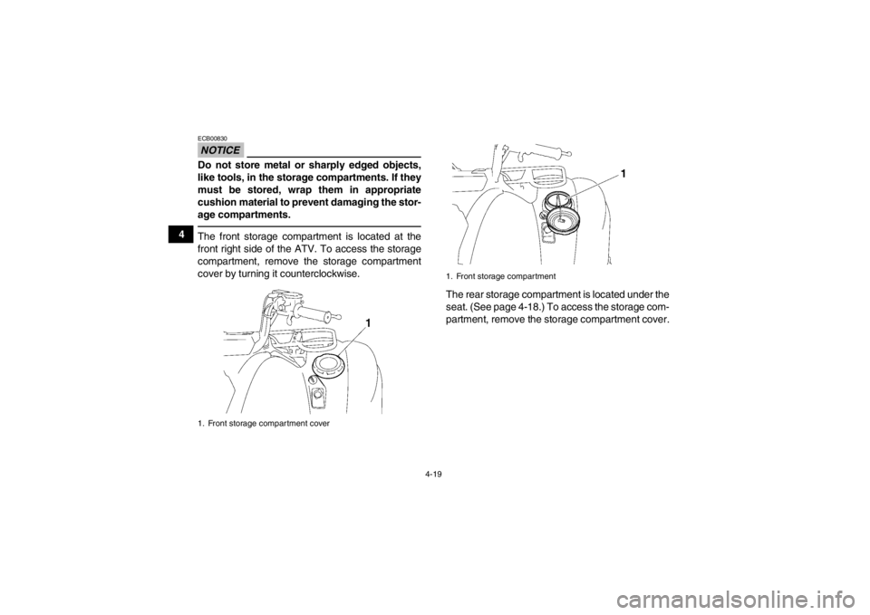
age compartments.The front storage compartment is located at the
front right side of the ATV. To access the storage
compartment, remove the storage compartment
cover by turning it counterclockwise.The rear storage compartment is located under the
seat. (See page 4-18.) To access the storage com-
partment, remove the storage compartment cover.1. Front storage compartment cover
1. Front storage compartment
U1HP61E0.book Page 19 Thursday, April 5, 2012 3:33 PM
Page 114 of 174
8-23
8
TIPIf the engine was started before checking the oil
level, be sure to warm up the engine sufficiently,
and then wait at least 10 minutes until the oil settles
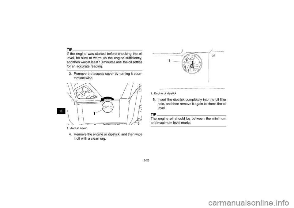
for an accurate reading.3. Remove the access cover by turning it coun-terclockwise.
4. Remove the engine oil dipstick, and then wipe it off with a clean rag. 5. Insert the dipstick completely into the oil filler
hole, and then remove it again to check the oil
level.
TIPThe engine oil should be between the minimum
and maximum level marks.
1. Access cover
1. Engine oil dipstick
U1HP61E0.book Page 23 Thursday, April 5, 2012 3:33 PM
Page 115 of 174
8-24
8
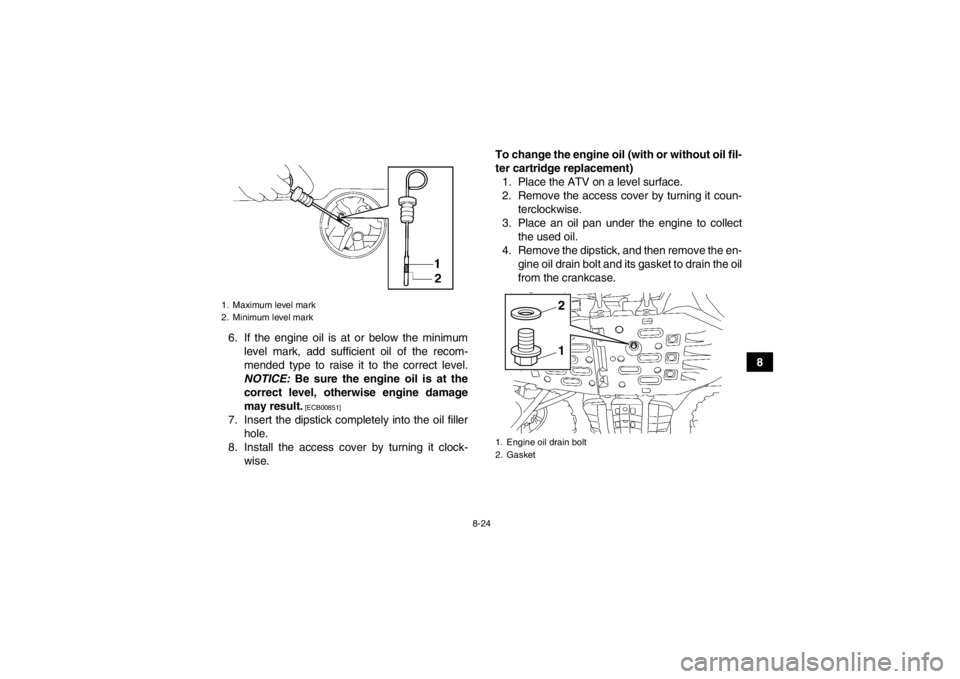
6. If the engine oil is at or below the minimum
level mark, add sufficient oil of the recom-
mended type to raise it to the correct level.
NOTICE: Be sure the engine oil is at the
correct level, otherwise engine damage
may result.
[ECB00851]
7. Insert the dipstick completely into the oil filler hole.
8. Install the access cover by turning it clock- wise. To change the engine oil (with or without oil fil-
ter cartridge replacement)
1. Place the ATV on a level surface.
2. Remove the access cover by turning it coun- terclockwise.
3. Place an oil pan under the engine to collect the used oil.
4. Remove the dipstick, and then remove the en- gine oil drain bolt and its gasket to drain the oil
from the crankcase.1. Maximum level mark
2. Minimum level mark
1. Engine oil drain bolt
2. Gasket
12
U1HP61E0.book Page 24 Thursday, April 5, 2012 3:33 PM
Page 118 of 174
8-27
8
●Make sure that no foreign material enters the
crankcase.12. Start the engine, and then let it idle for severalminutes while checking it for oil leakage. If oil
is leaking, immediately turn the engine off and
check for the cause.
13. Turn the engine off, wait at least ten minutes, and then check the oil level and correct it if
necessary.
14. Install the access cover by turning it clock- wise.EBU27306Final gear oil The final gear case must be checked for oil leak-
age before each ride. If any leakage is found, have
a Yamaha dealer check and repair the ATV. In ad-
dition, the final gear oil level must be checked and
the oil changed as follows at the intervals specified
in the periodic maintenance and lubrication chart.
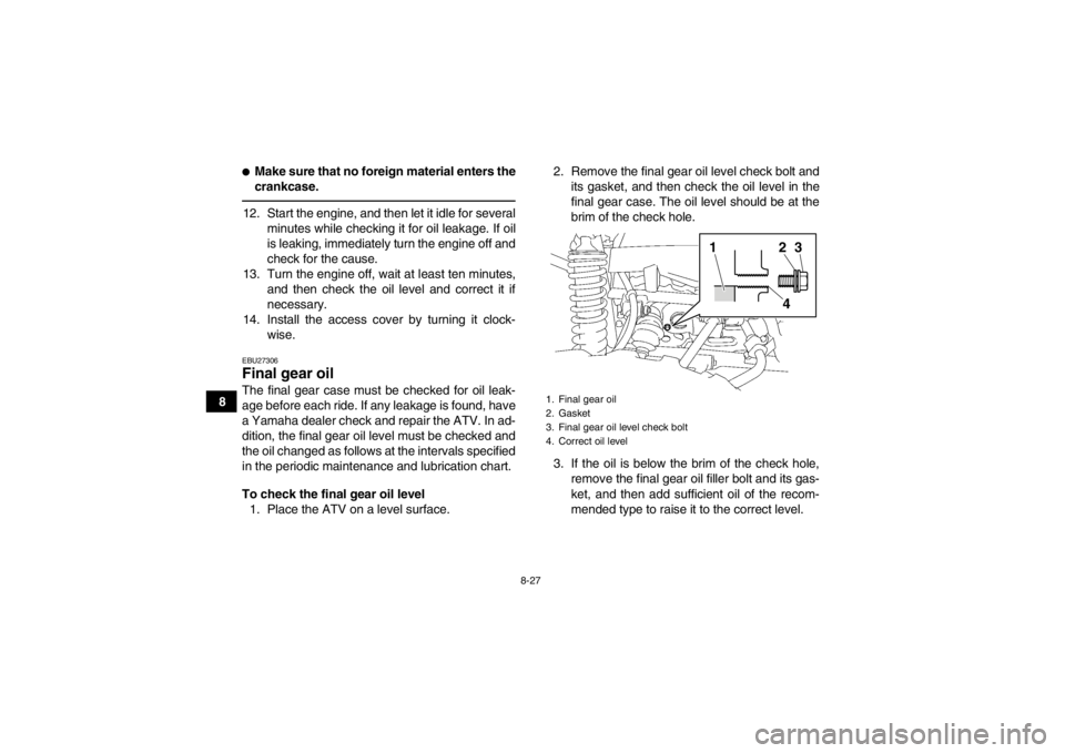
To check the final gear oil level1. Place the ATV on a level surface. 2. Remove the final gear oil level check bolt and
its gasket, and then check the oil level in the
final gear case. The oil level should be at the
brim of the check hole.
3. If the oil is below the brim of the check hole, remove the final gear oil filler bolt and its gas-
ket, and then add sufficient oil of the recom-
mended type to raise it to the correct level.
1. Final gear oil
2. Gasket
3. Final gear oil level check bolt
4. Correct oil level
1
243
U1HP61E0.book Page 27 Thursday, April 5, 2012 3:33 PM
Page 154 of 174
![YAMAHA GRIZZLY 700 2013 Owners Manual 8-63
86. Connect the headlight coupler.
7. Install the headlight bulb cover.
NOTICE:
Make sure the headlight bulb cover is se-
curely fitted and seated properly.
[ECB01080]
8. Install the cover at t YAMAHA GRIZZLY 700 2013 Owners Manual 8-63
86. Connect the headlight coupler.
7. Install the headlight bulb cover.
NOTICE:
Make sure the headlight bulb cover is se-
curely fitted and seated properly.
[ECB01080]
8. Install the cover at t](/img/51/50464/w960_50464-153.png)
8-63
86. Connect the headlight coupler.
7. Install the headlight bulb cover.
NOTICE:
Make sure the headlight bulb cover is se-
curely fitted and seated properly.
[ECB01080]
8. Install the cover at the rear of the headlight.
9. Adjust the headlight beam if necessary.EBU25551Adjusting a headlight beam NOTICEECB00690It is advisable to have a Yamaha dealer make
this adjustment.
To raise a headlight beam, turn the headlight beam
adjusting screw in direction (a).
To lower a headlight beam, turn the adjusting
screw in direction (b).EBU25642Replacing the tail/brake light bulb If the tail/brake light bulb burns out, replace it as
follows. 1. Remove panel H. (See page 8-10.)
2. Remove the tail/brake light bulb holder (to- gether with the bulb) by turning it counter-
clockwise.
1. Do not touch the glass part of the bulb.
1. Headlight beam adjusting screw
U1HP61E0.book Page 63 Thursday, April 5, 2012 3:33 PM