wheel YAMAHA GRIZZLY 700 2014 Owner's Guide
[x] Cancel search | Manufacturer: YAMAHA, Model Year: 2014, Model line: GRIZZLY 700, Model: YAMAHA GRIZZLY 700 2014Pages: 174, PDF Size: 4.2 MB
Page 157 of 174
8-65
8
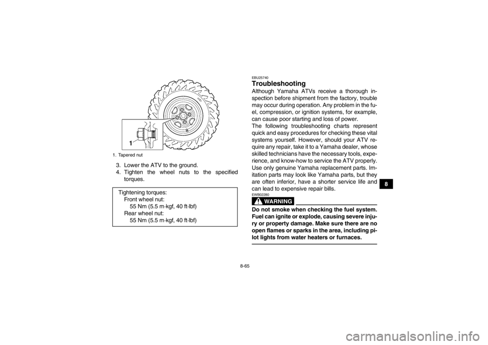
3. Lower the ATV to the ground.
4. Tighten the wheel nuts to the specified
torques.
EBU25740Troubleshooting Although Yamaha ATVs receive a thorough in-
spection before shipment from the factory, trouble
may occur during operation. Any problem in the fu-
el, compression, or ignition systems, for example,
can cause poor starting and loss of power.
The following troubleshooting charts represent
quick and easy procedures for checking these vital
systems yourself. However, should your ATV re-
quire any repair, take it to a Yamaha dealer, whose
skilled technicians have the necessary tools, expe-
rience, and know-how to service the ATV properly.
Use only genuine Yamaha replacement parts. Im-
itation parts may look like Yamaha parts, but they
are often inferior, have a shorter service life and
can lead to expensive repair bills.
WARNING
EWB02280Do not smoke when checking the fuel system.
Fuel can ignite or explode, causing severe inju-
ry or property damage. Make sure there are no
open flames or sparks in the area, including pi-
lot lights from water heaters or furnaces.
1. Tapered nutTightening torques:Front wheel nut:55 Nm (5.5 m·kgf, 40 ft·lbf)
Rear wheel nut: 55 Nm (5.5 m·kgf, 40 ft·lbf)
U2BG60E0.book Page 65 Monday, May 20, 2013 3:04 PM
Page 160 of 174

9-1
9
EBU25860
CLEANING AND STORAGE
EBU25881Cleaning Frequent, thorough cleaning of your ATV will not
only enhance its appearance but will improve its
general performance and extend the useful life of
many components.1. Before cleaning the ATV: a. Block off the end of the exhaust pipe toprevent water entry. A plastic bag and
strong rubber band may be used.
b. Make sure the spark plug and all filler caps are properly installed.
2. If the engine case is excessively greasy, apply degreaser with a paint brush. Do not apply de-
greaser to the wheel axles.
3. Rinse the dirt and degreaser off with a garden hose. Use only enough pressure to do the job.
WARNING! Wet brakes may have reduced
stopping ability, increasing the chance of
an accident. Test the brakes after washing.
Apply the brakes several times at slow
speeds to let friction dry out the linings.
[EWB02311]
NOTICE: Excessive water pressure
may cause water seepage and deteriora- tion of wheel bearings, brakes, transmis-
sion seals and electrical devices. Many
expensive repair bills have resulted from
improper high-pressure detergent applica-
tions such as those available in coin-oper-
ated car washers.
[ECB00711]
4. Once most of the dirt has been hosed off,
wash all surfaces with warm water and mild,
detergent-type soap. An old toothbrush or bot-
tle brush is handy for hard-to-reach places.
5. Rinse the ATV off immediately with clean wa- ter and dry all surfaces with a chamois, clean
towel or soft absorbing cloth.
6. Clean the seat with a vinyl upholstery cleaner to keep the cover pliable and glossy.
7. Automotive type wax may be applied to all painted and chrome plated surfaces. Avoid
combination cleaner-waxes. Many contain
abrasives which may mar the paint or protec-
tive finish. When finished cleaning, start the
engine and let it idle for several minutes.
U2BG60E0.book Page 1 Monday, May 20, 2013 3:04 PM
Page 161 of 174

9-2
9
EBU27261Storage Short-term
Always store your ATV in a cool, dry place and, if
necessary, protect it against dust with a porous
cover. NOTICE: Storing the ATV in a poorly ven-
tilated room or covering it with a tarp while it is
still wet, will allow water and humidity to seep
in and cause rust. To prevent corrosion, avoid
damp cellars, stables (because of the presence
of ammonia) and areas where strong chemi-
cals are stored.
[ECB00721]
Long-term
Before storing your ATV for several months: 1. Follow all the instructions in the “Cleaning” section of this chapter.
2. Fill up the fuel tank and add fuel stabilizer (if available) to prevent the fuel from deteriorat-
ing. 3. Perform the following steps to protect the cyl-
inder, piston rings, etc. from corrosion.a. Remove the spark plug cap and spark plug.
b. Pour a teaspoonful of engine oil into the spark plug bore.
c. Install the spark plug cap onto the spark plug, and then place the spark plug on the
cylinder head so that the electrodes are
grounded. (This will limit sparking during
the next step.)
d. Turn the engine over several times with the starter. (This will coat the cylinder wall with
oil.)
e. Remove the spark plug cap from the spark plug, and then install the spark plug and
the spark plug cap.
4. Lubricate all control cables and the pivoting points of all levers and pedals.
5. Check and, if necessary, correct the tire air pressure, and then block up the ATV so that
all of its wheels are off the ground. Alternative-
ly, turn the wheels a little every month in order
to prevent the tires from becoming degraded
in one spot.
Specified amount:
7.5 ml of stabilizer to each liter of fuel (or 1
oz of stabilizer to each gallon of fuel)U2BG60E0.book Page 2 Monday, May 20, 2013 3:04 PM
Page 163 of 174

10-1
10
EBU25961
SPECIFICATIONS
Dimensions:Overall length:2065 mm (81.3 in)
Overall width: 1180 mm (46.5 in)
Overall height:
1240 mm (48.8 in)
Seat height: 905 mm (35.6 in)
Wheelbase: 1250 mm (49.2 in)
Ground clearance:
275 mm (10.8 in)
Minimum turning radius: 3200 mm (126 in)Weight:Curb weight:
294.0 kg (648 lb)Noise and vibration level:Noise level (77/311/EEC):YFM700DE 79.0 dB(A)@3125 r/min
YFM700PE 79.0 dB(A)@3125 r/min (EUR)(FRA)(GBR)
YFM700PHE 79.0 dB(A)@3125 r/min
YFM700PLE 79.0 dB(A)@3125 r/min (EUR)(FRA)(GBR)
YFM700PSE 79.0 dB(A)@3125 r/min (EUR)(FRA)(GBR) Vibration on seat (EN1032, ISO5008):
YFM700DE Will not exceed 0.5 m/s²
YFM700PE Will not exceed 0.5 m/s² (EUR)(FRA)(GBR)
YFM700PHE Will not exceed 0.5 m/s²
YFM700PLE Will not exceed 0.5 m/s² (EUR)(FRA)(GBR)
YFM700PSE Will not exceed 0.5 m/s² (EUR)(FRA)(GBR)
Vibration on handlebar (EN1032, ISO5008):
YFM700DE Will not exceed 2.5 m/s²
YFM700PE Will not exceed 2.5 m/s² (EUR)(FRA)(GBR)
YFM700PHE Will not exceed 2.5 m/s²
YFM700PLE Will not exceed 2.5 m/s² (EUR)(FRA)(GBR)
YFM700PSE Will not exceed 2.5 m/s² (EUR)(FRA)(GBR)
Engine:Engine type:Liquid cooled 4-stroke, SOHC
Cylinder arrangement: Single cylinder
Displacement:
686 cm³
Bore × stroke:
102.0 × 84.0 mm (4.02 × 3.31 in)
Compression ratio: 10.00 : 1
Starting system:
Electric starter
Lubrication system: Wet sump
U2BG60E0.book Page 1 Monday, May 20, 2013 3:04 PM
Page 166 of 174

10-4
10
Tire air pressure (measured on cold tires):Recommended:Front: 35.0 kPa (0.350 kgf/cm², 5.0 psi)
Rear: 30.0 kPa (0.300 kgf/cm², 4.4 psi)
Minimum:
Front: 32.0 kPa (0.320 kgf/cm², 4.6 psi)
Rear:
27.0 kPa (0.270 kgf/cm², 4.0 psi)Front wheel:Wheel type:Panel wheel
Rim size:
12 x 6.0ATRear wheel:Wheel type:Panel wheel
Rim size:
12 x 7.5ATFront brake:Type:Disc brake
Operation:
Right hand operation
Specified brake fluid: DOT 4Rear brake:Type:
Disc brake Operation:
Left hand and right foot operation
Specified brake fluid: DOT 4
Front suspension:Type:Double wishbone
Spring/shock absorber type: Coil spring/oil damper
Wheel travel:
193 mm (7.6 in)Rear suspension:Type:Double wishbone
Spring/shock absorber type:
Coil spring/oil damper
Wheel travel: 232 mm (9.1 in)Electrical system:Ignition system:
TCI
Charging system: AC magnetoBattery:Model:
YTX20L-BS
Voltage, capacity: 12 V, 18.0 AhHeadlight:Bulb type:
Halogen bulb
U2BG60E0.book Page 4 Monday, May 20, 2013 3:04 PM
Page 167 of 174

10-5
10
Bulb voltage, wattage × quantity:Headlight:
12 V, 35.0/35.0 W × 2
Tail/brake light:
12 V, 5.0/21.0 W × 1
Meter lighting: EL (Electroluminescent)
Neutral indicator light: LED
Reverse indicator light:
LED
Coolant temperature warning light: LED
EPS warning light: YFM700PE LED
YFM700PHE LED
YFM700PLE LED
YFM700PSE LED
Park indicator light:
LED
On-Command four-wheel-drive/differential gear lock
indicator:
LCD
Engine trouble warning light: LED
High-range indicator light: LED
Low-range indicator light:
LED
Differential gear lock indicator light: LED
Fuses:Main fuse:40.0 A
Fuel injection system fuse:
15.0 A
EPS fuse: YFM700PE 40.0 A
YFM700PHE 40.0 A
YFM700PLE 40.0 A
YFM700PSE 40.0 A
Headlight fuse: 10.0 A
Signaling system fuse:
5.0 A
Ignition fuse: 10.0 A
Auxiliary DC jack fuse: 10.0 A
Four-wheel-drive motor fuse:
10.0 A
Radiator fan fuse: 20.0 AEBU30401For Europe only
The figures quoted are emission levels and are not
necessarily safe working levels. Whilst there is a
correlation between the emission and exposure
levels, this cannot be used reliably to determine
U2BG60E0.book Page 5 Monday, May 20, 2013 3:04 PM
Page 171 of 174

INDEX
AAccessories and loading ................................................ 6-6
Accessories, auxiliary jack ........................................... 4-23
Air filter element, cleaning ............................................ 8-39
Axle boots .................................................................... 8-51BBattery .......................................................................... 8-55
Brake fluid, changing ................................................... 8-48
Brake fluid level, checking ........................................... 8-47
Brake lever, front .......................................................... 4-14
Brake levers, checking and lubricating ........................ 8-52
Brake pads, checking the front and rear ...................... 8-46
Brake pedal and rear brake lever ................................. 4-14
Brake pedal, checking and lubricating ......................... 8-53
Brake pedal free play, adjusting ................................... 8-49
Brakes .......................................................................... 8-45
Brakes, front and rear .................................................... 5-3CCables, checking and lubricating ................................. 8-52
Carrier, front ................................................................. 4-21
Carrier, rear .................................................................. 4-21
Chassis fasteners .......................................................... 5-7
Cleaning ......................................................................... 9-1
Coolant .................................................................. 5-3, 8-31
Coolant temperature warning light ................................. 4-3DDifferential gear oil ................................................ 5-3, 8-29
Drive select lever ......................................................... 4-15 Drive select lever and driving in reverse ........................ 6-2
Drive select lever safety system cable, adjusting ........ 8-45
EEngine break-in .............................................................. 6-4
Engine oil ....................................................................... 5-3
Engine oil and oil filter cartridge ................................... 8-22
Engine stop switch ......................................................... 4-7
Engine trouble warning light .......................................... 4-3
EPS warning light (for EPS model) ................................ 4-3FFinal gear oil ......................................................... 5-3, 8-26
Four-wheel-drive/differential gear lock indicator ............ 4-4
Front and rear brake lever free play, checking ............ 8-48
Fuel ....................................................................... 4-16, 5-3
Fuel tank cap ............................................................... 4-15
Fuses, replacing .......................................................... 8-59HHandlebar switches ....................................................... 4-7
Headlight beam, adjusting ........................................... 8-62
Headlight bulb, replacing ............................................. 8-61
High-range indicator light ............................................... 4-2
Horn switch .................................................................... 4-8IIdentification numbers .................................................. 11-1
Indicator lights and warning lights .................................. 4-2
Instruments, lights and switches .................................... 5-7LLabel locations ............................................................... 1-1
U2BG60E0.book Page 1 Monday, May 20, 2013 3:04 PM
Page 172 of 174

Light switch .................................................................... 4-8
Low-range indicator light ................................................ 4-2MMain switch .................................................................... 4-1
Maintenance and lubrication chart ................................. 8-5
Maintenance chart, emission control system ................. 8-3
Model label ................................................................... 11-1
Multi-function display ...................................................... 4-5NNeutral indicator light ..................................................... 4-2OOn-Command differential gear lock switch .................. 4-10
On-Command four-wheel-drive switch ........................... 4-9
Override switch .............................................................. 4-8
Owner’s manual and tool kit ........................................... 8-2PPanels, removing and installing ................................... 8-10
Park indicator light .......................................................... 4-2
Parking ........................................................................... 6-5
Parking on a slope ......................................................... 6-5
Part locations ................................................................. 3-1RRadiator grills, removing .............................................. 8-19
Rear knuckle pivots, lubricating ................................... 8-54
Reverse indicator light .................................................... 4-2
Riding your ATV ............................................................. 7-1SSafety information .......................................................... 2-1
Seat .............................................................................. 4-18
Shock absorber assemblies, adjusting the front and rear ............................................................................. 4-21
Spark arrester, cleaning ............................................... 8-42 Spark plug, checking .................................................... 8-20
Specifications ............................................................... 10-1
Speed limiter ................................................................ 4-13
Stabilizer bushes, checking .......................................... 8-54
Starting the engine ......................................................... 6-1
Start switch ..................................................................... 4-8
Steering shaft, lubricating ............................................. 8-55
Storage ........................................................................... 9-2
Storage compartments ................................................. 4-18
TTail/brake light bulb, replacing ..................................... 8-63
Throttle lever ......................................................... 4-13, 5-4
Throttle lever free play, adjusting ................................. 8-44
Tires ............................................................................... 5-4
Troubleshooting ........................................................... 8-65
Troubleshooting charts ................................................. 8-66VValve clearance ............................................................ 8-45
V-belt case drain plug .................................................. 8-44
Vehicle identification number ....................................... 11-1WWheel hub bearings, checking ..................................... 8-54
Wheel, installing ........................................................... 8-64
Wheel, removing .......................................................... 8-64
U2BG60E0.book Page 2 Monday, May 20, 2013 3:04 PM