YAMAHA GRIZZLY 700 2016 Owner's Guide
Manufacturer: YAMAHA, Model Year: 2016, Model line: GRIZZLY 700, Model: YAMAHA GRIZZLY 700 2016Pages: 176, PDF Size: 4.47 MB
Page 31 of 176
2-6
2
WARNING
EWB00073Avoid Carbon Monoxide Poisoning
All engine exhaust contains carbon monoxide,
a deadly gas. Breathing carbon monoxide can
cause headaches, dizziness, drowsiness, nau-
sea, confusion, and eventually death.
Carbon Monoxide is a colorless, odorless,
tasteless gas which may be present even if you
do not see or smell any engine exhaust. Deadly
levels of carbon monoxide can collect rapidly
and you can quickly be overcome and unable
to save yourself. Also, deadly levels of carbon
monoxide can linger for hours or days in en-
closed or poorly ventilated areas. If you experi-
ence any symptoms of carbon monoxide
poisoning, leave the area immediately, get
fresh air, and SEEK MEDICAL TREATMENT.
Do not run engine indoors. Even if you try to
ventilate engine exhaust with fans or open
windows and doors, carbon monoxide can
rapidly reach dangerous levels.
Do not run engine in poorly ventilated or par-
tially enclosed areas such as barns, garages,
or carports.
Do not run engine outdoors where engine
exhaust can be drawn into a building through
openings such as windows and doors.
U2UD60E0.book Page 6 Tuesday, April 28, 2015 11:55 AM
Page 32 of 176
3-1
3
EBU17681
DESCRIPTION
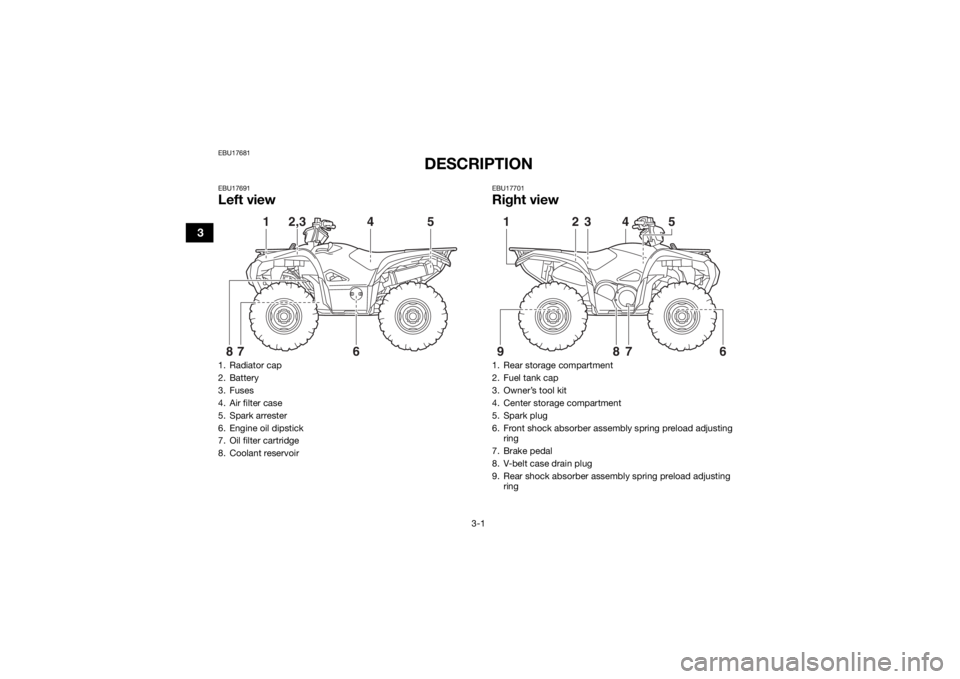
EBU17691Left view
EBU17701Right view
1. Radiator cap
2. Battery
3. Fuses
4. Air filter case
5. Spark arrester
6. Engine oil dipstick
7. Oil filter cartridge
8. Coolant reservoir
5
1
2,3
4
6
7
8
1. Rear storage compartment
2. Fuel tank cap
3. Owner’s tool kit
4. Center storage compartment
5. Spark plug
6. Front shock absorber assembly spring preload adjusting ring
7. Brake pedal
8. V-belt case drain plug
9. Rear shock absorber assembly spring preload adjusting ring
5
1
6
9
2
3
4
78
U2UD60E0.book Page 1 Tuesday, April 28, 2015 11:55 AM
Page 33 of 176
3-2
3
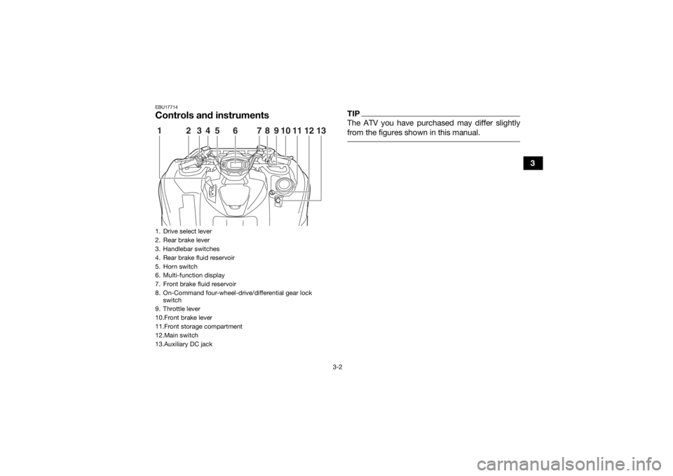
EBU17714Controls and instruments
TIPThe ATV you have purchased may differ slightly
from the figures shown in this manual.
1. Drive select lever
2. Rear brake lever
3. Handlebar switches
4. Rear brake fluid reservoir
5. Horn switch
6. Multi-function display
7. Front brake fluid reservoir
8. On-Command four-wheel-drive/differential gear lock switch
9. Throttle lever
10.Front brake lever
11.Front storage compartment
12.Main switch
13.Auxiliary DC jack1
5
234 6 78
10
911 13
12
U2UD60E0.book Page 2 Tuesday, April 28, 2015 11:55 AM
Page 34 of 176

4-1
4
EBU17737
INSTRUMENT AND CONTROL FUNCTIONS
EBU29912Main switchThe positions of the main switch are as follows:
“” (on)
All electrical systems are supplied with power. The
headlights and taillight come on when the light
switch is on, and the engine can be started. The
key cannot be removed.
“ ” (off)
All electrical systems are off. The key can be re-
moved.
1. Main switch
1
U2UD60E0.book Page 1 Tuesday, April 28, 2015 11:55 AM
Page 35 of 176
4-2
4
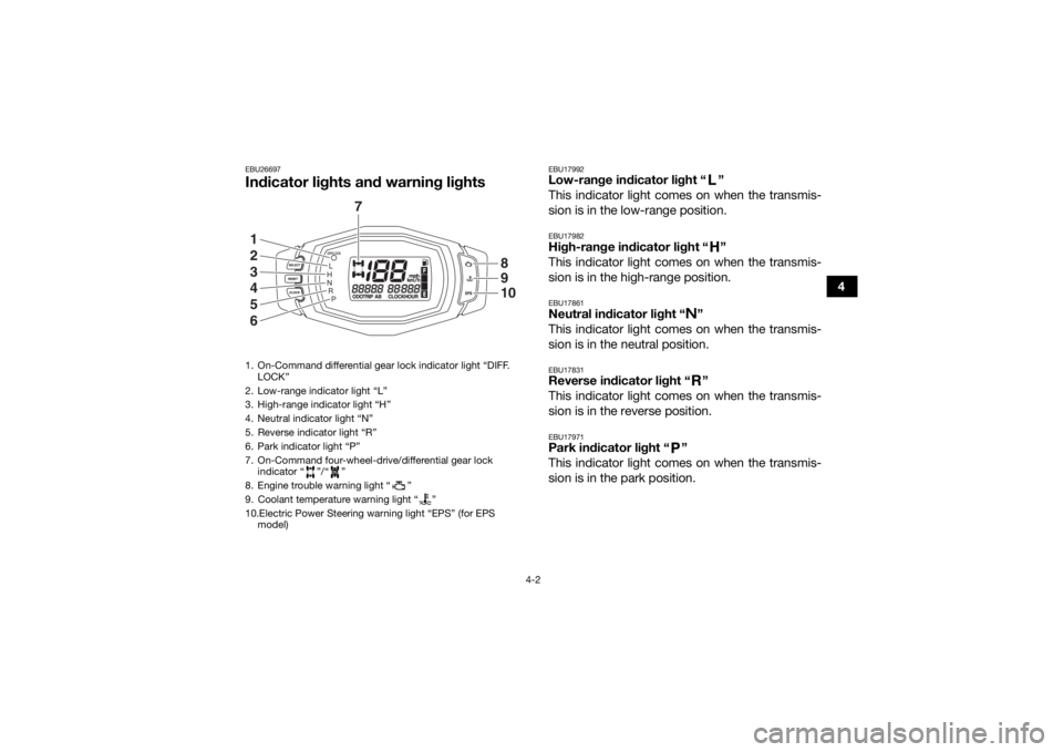
EBU26697Indicator lights and warning lights
EBU17992Low-range indicator light “ ”
This indicator light comes on when the transmis-
sion is in the low-range position.EBU17982High-range indicator light “ ”
This indicator light comes on when the transmis-
sion is in the high-range position.EBU17861Neutral indicator light “ ”
This indicator light comes on when the transmis-
sion is in the neutral position.EBU17831Reverse indicator light “ ”
This indicator light comes on when the transmis-
sion is in the reverse position.EBU17971Park indicator light “ ”
This indicator light comes on when the transmis-
sion is in the park position.
1. On-Command differential gear lock indicator light “DIFF.
LOCK”
2. Low-range indicator light “L”
3. High-range indicator light “H”
4. Neutral indicator light “N”
5. Reverse indicator light “R”
6. Park indicator light “P”
7. On-Command four-wheel-drive/differential gear lock indicator “ ”/“ ”
8. Engine trouble warning light “ ”
9. Coolant temperature warning light “ ”
10.Electric Power Steering warning light “EPS” (for EPS model)
7
1
2
3
4
5
6
8910
U2UD60E0.book Page 2 Tuesday, April 28, 2015 11:55 AM
Page 36 of 176
4-3
4
EBU34560Coolant temperature warning light “ ”
This warning light comes on when the engine
overheats. When this occurs during operation,
stop the engine as soon as it is safe to do so and
allow it to cool down for about 10 minutes.
The electrical circuit of the warning light can be
checked by turning the key to “ ” (on). The
warning light should come on for a few seconds,
and then go off.
If the warning light does not come on initially when
the key is turned to “ ” (on), or if the warning
light remains on, have a Yamaha dealer check the
electrical circuit.NOTICEECB02400The engine may overheat if the ATV is over-
loaded. In this case, reduce the load to spec-
ification.
The engine may also overheat if mud or dirt
has accumulated on the radiator (i.e., after
riding in wet terrain). In this case, have a
Yamaha dealer clean the radiator.
Start the engine after making sure that the
warning light is out. Continuous use while
the warning light is on may cause damage to
the engine.
EBU30482Engine trouble warning light “ ”
This warning light comes on or flashes when an
electrical circuit monitoring the engine is not work-
ing correctly. When this occurs, have a Yamaha
dealer check the self-diagnosis system. (See page
4-7 for an explanation of the self-diagnosis de-
vice.)
The electrical circuit of the warning light can be
checked by turning the key to “ ” (on). The
warning light should come on for a few seconds,
and then go off.
If the warning light does not come on initially when
the key is turned to “ ” (on), or if the warning
light remains on, have a Yamaha dealer check the
electrical circuit.
U2UD60E0.book Page 3 Tuesday, April 28, 2015 11:55 AM
Page 37 of 176

4-4
4
EBU30571Electric Power Steering warning light “EPS”
(for EPS model)
This warning light comes on when the key is
turned to “ ” (on), and then goes off once the
engine is started. If the warning light remains on or
comes on after the engine is started, the EPS sys-
tem may not be working correctly. When this oc-
curs, have a Yamaha dealer check the EPS
system.
The electrical circuit of the warning light can be
checked by turning the key to “ ” (on). If the
warning light does not come on, have a Yamaha
dealer check the electrical circuit.TIPIf the engine is stopped using the engine stop
switch and the key is in the “ ” (on) position,
the EPS warning light comes on to indicate that
the power assistance for the steering is not
functioning.
If the steering load is too heavy (i.e., excessive
steering use when the ATV is traveling at a slow
speed), the power assist is reduced to protect
the EPS motor from overheating.
EBU30451On-Command four-wheel-drive indicator “ ”,
On-Command differential gear lock
indicator “ ” and indicator light “DIFF. LOCK”
The On-Command four-wheel-drive indicator “ ”
comes on when the On-Command four-wheel-
drive switch is set to the “4WD” position.
The On-Command differential gear lock
indicator “ ” and the On-Command differential
gear lock indicator light “DIFF. LOCK” come on
when the On-Command differential gear lock
switch is set to the “LOCK” position.TIPDue to the synchronizing mechanism in the dif-
ferential gear case, the four-wheel-drive indica-
tor may not come on until the ATV starts
moving.
When the On-Command differential gear lock
switch is set to “LOCK” or “4WD”, the
indicator “ ” and the indicator light “DIFF.
LOCK” will flash until the differential gear is
completely locked or unlocked. If the indicator
and the indicator light continue to flash, the dif-
ferential is not completely locked or unlocked.
In this case, start moving to allow time for the
differential to lock or unlock.
U2UD60E0.book Page 4 Tuesday, April 28, 2015 11:55 AM
Page 38 of 176

4-5
4
EBU30496Multi-function display The multi-function display is equipped with the
following:
a speedometer
an odometer
two tripmeters (which show the distance trav-
eled since they were last set to zero)
a clock
an hour meter (which shows the total time the
engine has been running)
a fuel meter
a self-diagnosis device
Odometer and tripmeter modes
Pushing the “SELECT” button switches the dis-
play between the odometer mode “ODO” and the
tripmeter modes “TRIP A” and “TRIP B” in the fol-
lowing order:
ODO → TRIP A → TRIP B → ODO
To reset a tripmeter, select it by pushing the “SE-
LECT” button, and then push the “RESET” button
for at least three seconds. The tripmeters can be
used to estimate the distance that can be traveled
with a full tank of fuel. This information will enable
you to plan future fuel stops.
TIPPushing and holding in th e “SELECT” button, and
turning the key to “ ” (on) while the button is
pushed, switches the display between “mph” and
“km/h”.
1. “SELECT” button
2. “RESET” button
3. “CLOCK” button
4. Speedometer
5. Fuel meter
6. Clock/Hour meter
7. Odometer/Tripmeter A/Tripmeter B
4
5
7
6
123U2UD60E0.book Page 5 Tuesday, April 28, 2015 11:55 AM
Page 39 of 176

4-6
4
Clock mode
Pushing the “CLOCK” button switches the display
between the clock mode “CLOCK” and the hour
meter mode “HOUR” in the following order:
CLOCK →
HOUR → CLOCK
To set the clock
1. Set the display to the clock mode.
2. Push the “SELECT” button and “RESET” but- ton together for at least three seconds.
3. When the hour digits start flashing, push the “RESET” button to set the hours.
4. Push the “SELECT” button, and the minute digits will start flashing.
5. Push the “RESET” button to set the minutes.
6. Push the “SELECT” button and then release it to start the clock.
Fuel meter
The fuel meter indicates the amount of fuel in the
fuel tank. The display segments of the fuel meter
disappear from “F” (full) towards “E” (empty) as
the fuel level decreases. When the “E” segment
disappears and the fuel level warning indicator
flashes, refuel as soon as possible.
TIPThis fuel meter is equipped with a self-diagnosis
system. If the electrical circuit is not working cor-
rectly, all the display segments and fuel level
warning indicator will start flashing. If this occurs,
have a Yamaha dealer check the electrical circuit. 1. Fuel level warning indicator
2. Fuel meter
3. “E” segment
1
23
U2UD60E0.book Page 6 Tuesday, April 28, 2015 11:55 AM
Page 40 of 176
4-7
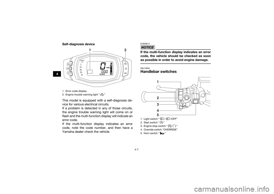
4Self-diagnosis device
This model is equipped with a self-diagnosis de-
vice for various electrical circuits.
If a problem is detected in any of those circuits,
the engine trouble warning light will come on or
flash and the multi-function display will indicate an
error code.
If the multi-function display indicates an error
code, note the code number, and then have a
Yamaha dealer check the vehicle.
NOTICEECB00812If the multi-function display indicates an error
code, the vehicle should be checked as soon
as possible in order to avoid engine damage. EBU18065Handlebar switches
1. Error code display
2. Engine trouble warning light “ ”
1
2
1. Light switch “ / /OFF”
2. Start switch “ ”
3. Engine stop switch “ / ”
4. Override switch “OVERRIDE”
5. Horn switch “ ”
45321
U2UD60E0.book Page 7 Tuesday, April 28, 2015 11:55 AM