light YAMAHA GRIZZLY 700 2018 Owners Manual
[x] Cancel search | Manufacturer: YAMAHA, Model Year: 2018, Model line: GRIZZLY 700, Model: YAMAHA GRIZZLY 700 2018Pages: 176, PDF Size: 4.47 MB
Page 8 of 176

EBU17421
TABLE OF CONTENTS
LOCATION OF THE WARNING AND
SPECIFICATION LABELS .............................. 1-1
SAFETY INFORMATION ................................ 2-1
DESCRIPTION................................................ 3-1Left view ...................................................... 3-1
Right view.................................................... 3-1
Controls and instruments............................ 3-2
INSTRUMENT AND CONTROL
FUNCTIONS ................................................... 4-1 Main switch ................................................. 4-1
Indicator lights and warning lights .............. 4-2
Multi-function display ................................. 4-5
Handlebar switches .................................... 4-8
Throttle lever ............................................. 4-13
Speed limiter ............................................. 4-14
Front brake lever ....................................... 4-15
Brake pedal and rear brake lever .............. 4-15
Drive select lever ....................................... 4-16
Fuel tank cap............................................. 4-16
Fuel ........................................................... 4-16
Seat ........................................................... 4-18 Storage compartments ............................. 4-19
Front carrier .............................................. 4-23
Rear carrier ............................................... 4-23
Adjusting the front and rear shock
absorber assemblies ............................. 4-23
Trailer hitch (YFM70GPHJ / YFM70GPSJ / YFM70GPLJ) .................. 4-24
Auxiliary DC jack....................................... 4-24
PRE-OPERATION CHECKS .......................... 5-1 Fuel ............................................................. 5-3
Engine oil .................................................... 5-3
Final gear oil ............................................... 5-3
Differential gear oil ...................................... 5-3
Coolant ....................................................... 5-3
Front and rear brakes ................................. 5-3
Throttle lever ............................................... 5-4
Tires ............................................................ 5-4
Chassis fasteners ....................................... 5-6
Instruments, lights and switches ................ 5-7
OPERATION .................................................. 6-1 Starting the engine ..................................... 6-1UB1A60E0.book Page 1 Wednesday, March 1, 2017 2:36 PM
Page 10 of 176

Checking and lubricating the brake pedal ....................................................... 8-51
Checking the wheel hub bearings............. 8-51
Checking the stabilizer bushes ................. 8-51
Lubricating the rear knuckle pivots ........... 8-52
Lubricating the steering shaft ................... 8-52
Battery....................................................... 8-53
Replacing a fuse ....................................... 8-57
Replacing a headlight bulb ....................... 8-59
Adjusting a headlight beam ...................... 8-61
Tail/brake light........................................... 8-62
Removing a wheel ..................................... 8-62
Installing a wheel....................................... 8-62
Troubleshooting ........................................ 8-63
Troubleshooting charts ............................. 8-64
CLEANING AND STORAGE ........................... 9-1 Cleaning ...................................................... 9-1
Storage........................................................ 9-2
SPECIFICATIONS ........................................ 10-1
CONSUMER INFORMATION ....................... 11-1 Identification numbers .............................. 11-1
INDEX ........................................................... 12-1
UB1A60E0.book Page 3 Wednesday, March 1, 2017 2:36 PM
Page 27 of 176

2-3
2
technique described in this manual on level
ground. Avoid crossing the side of a steep hill if
possible.
Always use proper procedures if you stall or roll
backwards when climbing a hill. To avoid stall-
ing, use the proper gear range and maintain a
steady speed when climbing a hill. If you stall or
roll backwards, follow the special procedure for
braking described in this manual. Dismount on
the uphill side or to a side if pointed straight up-
hill. Turn the ATV around and remount, following
the procedure described in this manual.
Always check for obstacles before operating in
a new area.
Never attempt to operate over large obstacles,
such as large rocks or fallen trees. Always follow
proper procedures when operating over obsta-
cles as described in this manual.
Always be careful when skidding or sliding.
Learn to safely control skidding or sliding by
practicing at low speeds and on level, smooth
terrain. On extremely slippery surfaces, such as
ice, go slowly and be very cautious in order to
reduce the chance of skidding or sliding out of
control.
Never operate an ATV in fast flowing water or in
water deeper than that recommended in this
manual. Remember that wet brakes may have
reduced stopping ability. Test your brakes after
leaving water. If necessary, apply them several
times to let friction dry out the linings.
Always be sure there are no obstacles or people
behind you when you operate in reverse. When
it is safe to proceed in reverse, go slowly.
Always use the size and type of tires specified in
this manual.
Always maintain proper tire pressure as de-
scribed in this manual.
Never exceed the stated load capacity for an
ATV. Cargo should be properly distributed and
securely attached. Reduce speed and follow in-
structions in this manual for carrying cargo or
pulling a trailer. Allow greater distance for brak-
ing.
Do not operate your ATV during darkness un-
less it is equipped with a properly functioning
headlight. Off-road riding is inherently danger-
ous and additionally, off-road trails do not have
streetlights to guide you.
UB1A60E0.book Page 3 Wednesday, March 1, 2017 2:36 PM
Page 28 of 176

2-4
2
Never maintain an ATV without proper knowl-
edge. Contact an authorized ATV dealer to in-
form you on basic ATV maintenance. Certain
maintenance can only be carried out by certified
staff.
In the event of an accident 1. If serious injuries are incurred, you may be safer staying next to your vehicle; it may
shield you from oncoming riders. Depending
on your injuries and position in the trail; you
must make a judgment call as to whether you
should move to a position off the trail. If you
have sustained head, neck, or back injuries,
or cannot feel your limbs, you should not
move. Keep your helmet on and remain mo-
tionless. Lie down next to your vehicle and
wait for help.
2. If less serious injuries are incurred and you can walk, then move to a position off the trail.
Check yourself for injuries and apply first aid
as needed.
3. If your injuries are light, when safe to do so, move your vehicle off the trail to avoid colli-
sions with oncoming riders. Check for injuries
and apply first aid as necessary. If you can
physically operate your vehicle, inspect your vehicle. If the vehicle is in safe operating con-
dition and you can safely operate it, restart it
and ride gently back to camp or other known
location where you can receive medical at-
tention. If necessary, contact your riding party
or local authorities to let them know where
you are and what has happened.
In the event of a breakdown 1. If your vehicle will not restart or is not in safe operating condition, turn off the main switch
and engine stop switch. If the breakdown oc-
curs at twilight or night, leave the main switch
on so that your lights may warn other riders of
your stopped vehicle.
2. Get out of danger. Check for oncoming vehi- cles and when safe, push your vehicle to the
side of the trail or even off the main trail to
avoid any possible collisions with oncoming
riders. If you cannot move your vehicle by
yourself, when safe, walk to the nearest van-
tage point and signal an oncoming rider to
help you push your vehicle to a safe place off
the trail.
3. Inspect your vehicle for any immediate haz- ardous conditions. The most obvious hazard-
ous conditions are leaking fuel and
UB1A60E0.book Page 4 Wednesday, March 1, 2017 2:36 PM
Page 30 of 176
2-6
2gerous loss of lights or engine power. Also, the
battery tends to discharge more quickly if elec-
trical accessories are added.
WARNING
EWB00073Avoid Carbon Monoxide Poisoning
All engine exhaust contains carbon monoxide,
a deadly gas. Breathing carbon monoxide can
cause headaches, dizziness, drowsiness, nau-
sea, confusion, and eventually death.
Carbon Monoxide is a colorless, odorless,
tasteless gas which may be present even if you
do not see or smell any engine exhaust. Deadly
levels of carbon monoxide can collect rapidly
and you can quickly be overcome and unable
to save yourself. Also, deadly levels of carbon
monoxide can linger for hours or days in en-
closed or poorly ventilated areas. If you experi-
ence any symptoms of carbon monoxide
poisoning, leave the area immediately, get
fresh air, and SEEK MEDICAL TREATMENT.
Do not run engine indoors. Even if you try to
ventilate engine exhaust with fans or open
windows and doors, carbon monoxide can
rapidly reach dangerous levels.
Do not run engine in poorly ventilated or par-
tially enclosed areas such as barns, garages,
or carports.
Do not run engine outdoors where engine
exhaust can be drawn into a building through
openings such as windows and doors.
UB1A60E0.book Page 6 Wednesday, March 1, 2017 2:36 PM
Page 32 of 176
3-2
3
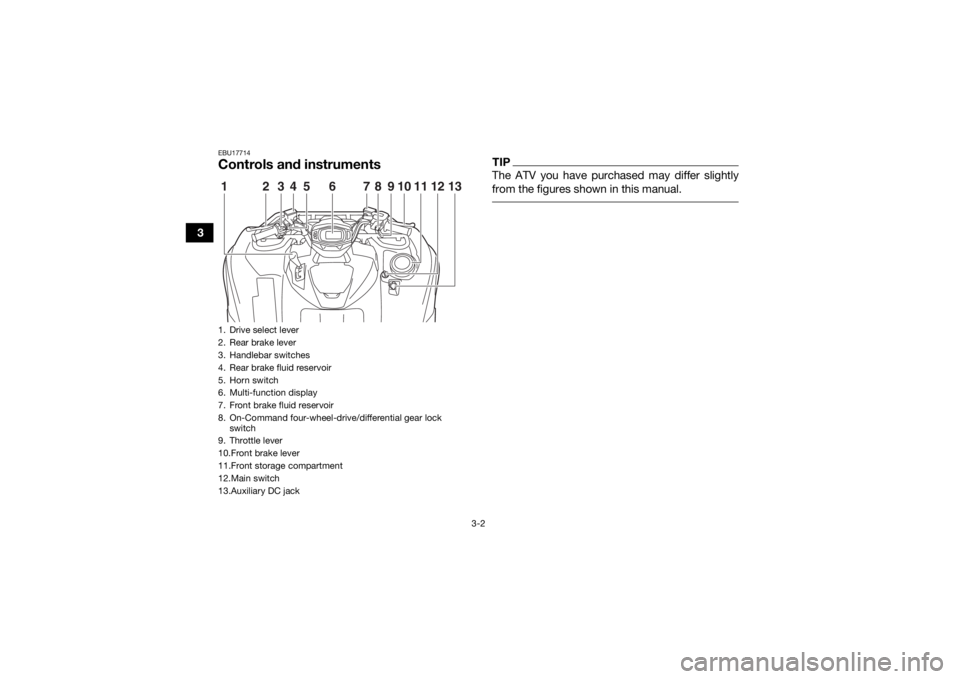
EBU17714Controls and instruments
TIPThe ATV you have purchased may differ slightly
from the figures shown in this manual.
1. Drive select lever
2. Rear brake lever
3. Handlebar switches
4. Rear brake fluid reservoir
5. Horn switch
6. Multi-function display
7. Front brake fluid reservoir
8. On-Command four-wheel-drive/differential gear lock switch
9. Throttle lever
10.Front brake lever
11.Front storage compartment
12.Main switch
13.Auxiliary DC jack1
5
234 6 78
10
911 13
12
UB1A60E0.book Page 2 Wednesday, March 1, 2017 2:36 PM
Page 33 of 176
4-1
4
EBU17738
INSTRUMENT AND CONTROL FUNCTIONS
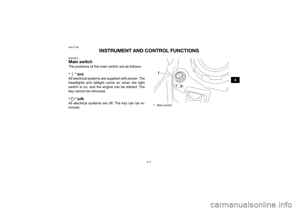
EBU29912Main switchThe positions of the main switch are as follows:
“” (on)
All electrical systems are supplied with power. The
headlights and taillight come on when the light
switch is on, and the engine can be started. The
key cannot be removed.
“ ” (off)
All electrical systems are off. The key can be re-
moved.
1. Main switch
1
UB1A60E0.book Page 1 Wednesday, March 1, 2017 2:36 PM
Page 34 of 176
4-2
4
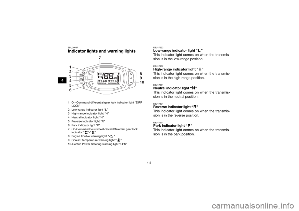
EBU26697Indicator lights and warning lights
EBU17992Low-range indicator light “ ”
This indicator light comes on when the transmis-
sion is in the low-range position.EBU17982High-range indicator light “ ”
This indicator light comes on when the transmis-
sion is in the high-range position.EBU17861Neutral indicator light “ ”
This indicator light comes on when the transmis-
sion is in the neutral position.EBU17831Reverse indicator light “ ”
This indicator light comes on when the transmis-
sion is in the reverse position.EBU17971Park indicator light “ ”
This indicator light comes on when the transmis-
sion is in the park position.
1. On-Command differential gear lock indicator light “DIFF. LOCK”
2. Low-range indicator light “L”
3. High-range indicator light “H”
4. Neutral indicator light “N”
5. Reverse indicator light “R”
6. Park indicator light “P”
7. On-Command four-wheel-drive/differential gear lock indicator “ ”/“ ”
8. Engine trouble warning light “ ”
9. Coolant temperature warning light “ ”
10.Electric Power Steering warning light “EPS”
7
1
2
3
4
5
6
8910
UB1A60E0.book Page 2 Wednesday, March 1, 2017 2:36 PM
Page 35 of 176

4-3
4
EBU34560Coolant temperature warning light “ ”
This warning light comes on when the engine
overheats. When this occurs during operation,
stop the engine as soon as it is safe to do so and
allow it to cool down for about 10 minutes.
The electrical circuit of the warning light can be
checked by turning the key to “ ” (on). The
warning light should come on for a few seconds,
and then go off.
If the warning light does not come on initially when
the key is turned to “ ” (on), or if the warning
light remains on, have a Yamaha dealer check the
electrical circuit.NOTICEECB02400The engine may overheat if the ATV is over-
loaded. In this case, reduce the load to spec-
ification.
The engine may also overheat if mud or dirt
has accumulated on the radiator (i.e., after
riding in wet terrain). In this case, have a
Yamaha dealer clean the radiator.
Start the engine after making sure that the
warning light is out. Continuous use while
the warning light is on may cause damage to
the engine.
EBU30483Engine trouble warning light “ ”
This warning light comes on or flashes if a problem
is detected in the electrical circuit monitoring the
engine. When this occurs, the display will indicate
an error code (see page 4-7). Have a Yamaha
dealer check the self-diagnosis system.
The electrical circuit of the warning light can be
checked by turning the key to “ ” (on). The
warning light should come on for a few seconds,
and then go off.
If the warning light does not come on initially when
the key is turned to “ ” (on), or if the warning
light remains on, have a Yamaha dealer check the
vehicle.EBU30511Electric Power Steering warning light “EPS”
This warning light comes on when the key is
turned to “ ” (on), and then goes off once the
engine is started. If the warning light remains on or
comes on after the engine is started, the EPS sys-
UB1A60E0.book Page 3 Wednesday, March 1, 2017 2:36 PM
Page 36 of 176
4-4
4tem may not be working correctly. When this oc-
curs, have a Yamaha dealer check the EPS
system.
The electrical circuit of the warning light can be
checked by turning the key to “ ” (on). If the
warning light does not come on, have a Yamaha
dealer check the electrical circuit.
TIP
If the engine is stopped using the engine stop
switch and the key is in the “ ” (on) position,
the EPS warning light comes on to indicate that
the power assistance for the steering is not
functioning.
If the steering load is too heavy (i.e., excessive
steering use when the ATV is traveling at a slow
speed), the power assist is reduced to protect
the EPS motor from overheating. EBU30451On-Command four-wheel-drive indicator “ ”,
On-Command differential gear lock
indicator “ ” and indicator light “DIFF. LOCK”
The On-Command four-wheel-drive indicator “ ”
comes on when the On-Command four-wheel-
drive switch is set to the “4WD” position. The On-Command differential gear lock
indicator “ ” and the On-Command differential
gear lock indicator light “DIFF. LOCK” come on
when the On-Command differential gear lock
switch is set to the “LOCK” position.
TIP
Due to the synchronizing mechanism in the dif-
ferential gear case, the four-wheel-drive indica-
tor may not come on until the ATV starts
moving.
When the On-Command differential gear lock
switch is set to “LOCK” or “4WD”, the
indicator “ ” and the indicator light “DIFF.
LOCK” will flash until the differential gear is
completely locked or unlocked. If the indicator
and the indicator light continue to flash, the dif-
ferential is not completely locked or unlocked.
In this case, start moving to allow time for the
differential to lock or unlock.
UB1A60E0.book Page 4 Wednesday, March 1, 2017 2:36 PM