YAMAHA GRIZZLY 700 2021 Owners Manual
Manufacturer: YAMAHA, Model Year: 2021, Model line: GRIZZLY 700, Model: YAMAHA GRIZZLY 700 2021Pages: 178, PDF Size: 4.73 MB
Page 151 of 178
9-52
9
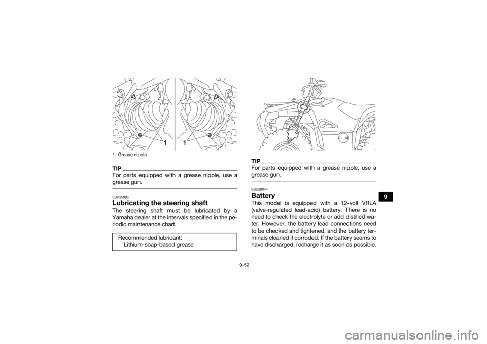
TIPFor parts equipped with a grease nipple, use a
grease gun. EBU25096Lubricating the steering shaftThe steering shaft must be lubricated by a
Yamaha dealer at the intervals specified in the pe- riodic maintenance chart.
TIPFor parts equipped with a grease nipple, use a
grease gun. EBU2904FBatteryThis model is equipped with a 12-volt VRLA
(valve-regulated lead-acid) battery. There is no
need to check the electrolyte or add distilled wa-
ter. However, the battery lead connections need
to be checked and tightened, and the battery ter-
minals cleaned if corroded. If the battery seems to
have discharged, recharge it as soon as possible.
1. Grease nippleRecommended lubricant: Lithium-soap-based grease
1
1
UBFE60E0.book Page 52 Tuesday, August 18, 2020 10:50 AM
Page 152 of 178
9-53
9
TIPWear gloves and eye protection in a ventilated
area away from sparks and open flames. Wash
hands after handling.
It is recommended to have the battery serviced
by a Yamaha dealer.
WARNING
EWB02161Battery electrolyte is poisonous and danger-
ous, as it contains sulfuric acid, which can cau-
se severe burns. Avoid contact with skin, eyes
or clothing. Always shield your eyes when
working near batteries.
Antidote:
EXTERNAL: Flush with water.
INTERNAL: Drink large quantities of water or
milk. Follow with milk of magnesia, beaten egg
or vegetable oil. Call a physician immediately.
EYES: Flush with water for 15 minutes and get
prompt medical attention.
Batteries produce explosive gases. Keep
sparks, flame, cigarettes or other sources of
ignition away. Ventilate when charging or using
in an enclosed space. KEEP OUT OF REACH OF CHILDREN.
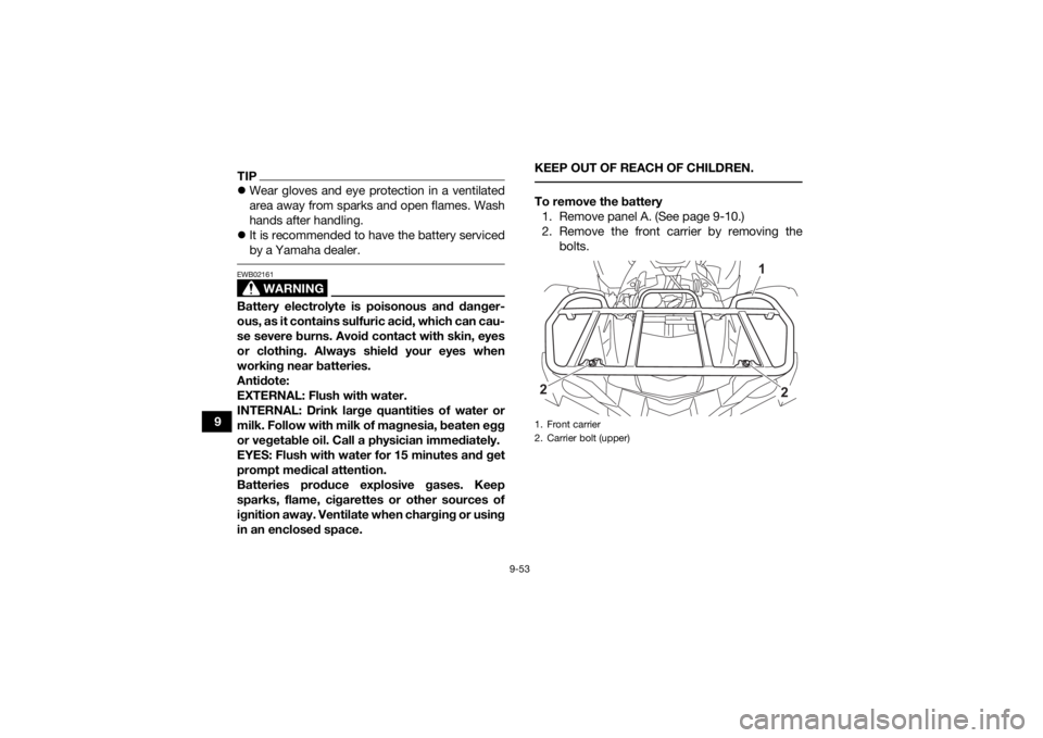
To remove the battery
1. Remove panel A. (See page 9-10.)
2. Remove the front carrier by removing the bolts.1. Front carrier
2. Carrier bolt (upper)
1
2
2
UBFE60E0.book Page 53 Tuesday, August 18, 2020 10:50 AM
Page 153 of 178
9-54
9
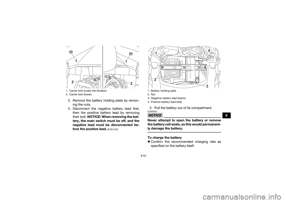
3. Remove the battery holding plate by remov-
ing the nuts.
4. Disconnect the negative battery lead first, then the positive battery lead by removing
their bolt. NOTICE: When removing the bat-
tery, the main switch must be off, and the
negative lead must be disconnected be-
fore the positive lead.
[ECB01002]
5. Pull the battery out of its compartment.NOTICEECB00622Never attempt to open the battery or remove
the battery cell seals, as this would permanent-
ly damage the battery. To charge the battery
Confirm the recommended charging rate as
specified on the battery itself.
1. Carrier bolt (under the fenders)
2. Carrier bolt (lower)
1
2
2
1
1. Battery holding plate
2. Nut
3. Negative battery lead (blackF
4. Positive battery lead (redF
12
43
UBFE60E0.book Page 54 Tuesday, August 18, 2020 10:50 AM
Page 154 of 178
9-55
9
Select a suitable charger and follow the manu-
facturer’s instructions.
NOTICEECB00933To charge a VRLA (valve-regulated lead-acid)
battery, a special battery charger is required.
Using a conventional battery charger will dam-
age the battery. To store the battery
If the ATV will not be used for more than one
month, remove the battery, fully charge it, and
then place it in a cool, dry place.
If the battery will be stored for more than two
months, check it at least once a month and fully
charge it if necessary.NOTICEECB00942Always keep the battery charged. Storing the
battery in a discharged state for an extended
period of time will cause permanent battery
damage.
Do not store the battery in an excessively
cold or warm place [below freezing or above
30 °C (90 °F)].
To install the battery
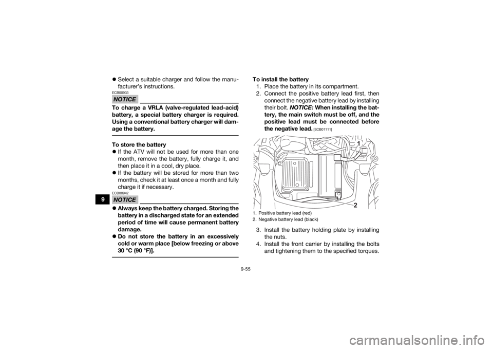
1. Place the battery in its compartment.
2. Connect the positive battery lead first, then connect the negative battery lead by installing
their bolt. NOTICE: When installing the bat-
tery, the main switch must be off, and the
positive lead must be connected before
the negative lead.
[ECB01111]
3. Install the battery holding plate by installing the nuts.
4. Install the front carrier by installing the bolts and tightening them to the specified torques.1. Positive battery lead (red)
2. Negative battery lead (black)
12
UBFE60E0.book Page 55 Tuesday, August 18, 2020 10:50 AM
Page 155 of 178

9-56
9
5. Install the panel.
TIP
Make sure the positive and negative battery
leads are installed as shown.
Fully charge the battery before installing it.
EBU30525Replacing a fuse
Tightening torques:
Carrier bolt (upper):34 N·m (3.4 kgf·m, 25 lb·ft)
Carrier bolt (lower): 34 N·m (3.4 kgf·m, 25 lb·ft)
Carrier bolt (under the fenders): 7 N·m (0.7 kgf·m, 5.2 lb·ft)
1. Fuse box
2. Main fuse
3. EPS fuse
4. Fuel injection system spare fuse
5. Fuel injection system fuse
2345
1
UBFE60E0.book Page 56 Tuesday, August 18, 2020 10:50 AM
Page 156 of 178
9-57
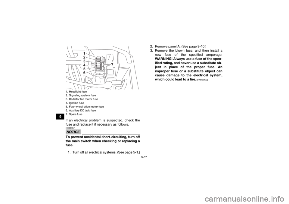
9If an electrical problem is suspected, check the
fuse and replace it if necessary as follows.
NOTICEECB00641To prevent accidental short-circuiting, turn off
the main switch when checking or replacing a
fuse. 1. Turn off all electrical systems. (See page 5-1.) 2. Remove panel A. (See page 9-10.)
3. Remove the blown fuse, and then install a
new fuse of the specified amperage.
WARNING! Always use a fuse of the spec-
ified rating, and never use a substitute ob-
ject in place of the proper fuse. An
improper fuse or a substitute object can
cause damage to the electrical system,
which could lead to a fire.
[EWB02173]
1. Headlight fuse
2. Signaling system fuse
3. Radiator fan motor fuse
4. Ignition fuse
5. Four-wheel-drive motor fuse
6. Auxiliary DC jack fuse
7. Spare fuse
123456
7
UBFE60E0.book Page 57 Tuesday, August 18, 2020 10:50 AM
Page 157 of 178

9-58
9
4. Turn on the main switch and start the engine.
5. If the fuse immediately blows again, have a Yamaha dealer check the vehicle.
6. Install the panel.
EBU34713Replacing a headlight bulbLeft and right headlights
This model is equipped with LED-type headlights.
If a headlight does not come on, have a Yamaha
dealer check the vehicle and replace the headlight
if necessary.TIP When the headlights are set to low beam, only
the top half of each lamp will illuminate.
When the headlights are set to high beam, both
halves of each lamp will illuminate. Handlebar-mounted light
If the handlebar-mounted light bulb burns out, re-
place it with the specified bulb as follows.
1. Remove the handlebar-mounted light cover by removing the quick fasteners.
Specified fuses:
Main fuse:40.0 A
Headlight fuse: 10.0 A
Ignition fuse: 10.0 A
Four-wheel-drive motor fuse: 10.0 A
Signaling system fuse: 10.0 A
Auxiliary DC jack fuse: 10.0 A
Radiator fan motor fuse: 20.0 A
Fuel injection system fuse: 15.0 A
EPS fuse: 40.0 A
UBFE60E0.book Page 58 Tuesday, August 18, 2020 10:50 AM
Page 158 of 178
9-59
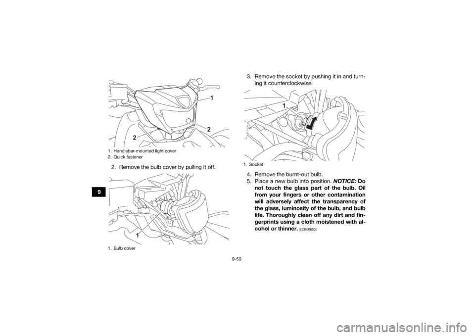
92. Remove the bulb cover by pulling it off. 3. Remove the socket by pushing it in and turn-
ing it counterclockwise.
4. Remove the burnt-out bulb.
5. Place a new bulb into position. NOTICE: Do
not touch the glass part of the bulb. Oil
from your fingers or other contamination
will adversely affect the transparency of
the glass, luminosity of the bulb, and bulb
life. Thoroughly clean off any dirt and fin-
gerprints using a cloth moistened with al-
cohol or thinner.
[ECB00653]
1. Handlebar-mounted light cover
2. Quick fastener
1. Bulb cover
1
2
2
1
1. Socket
1
UBFE60E0.book Page 59 Tuesday, August 18, 2020 10:50 AM
Page 159 of 178
![YAMAHA GRIZZLY 700 2021 Owners Manual 9-60
9
6. Install the socket by pushing it in and turning
it clockwise.
7. Install the bulb cover. NOTICE: Make sure
the bulb cover is securely fitted over the
socket and seated properly.
[ECB03320] YAMAHA GRIZZLY 700 2021 Owners Manual 9-60
9
6. Install the socket by pushing it in and turning
it clockwise.
7. Install the bulb cover. NOTICE: Make sure
the bulb cover is securely fitted over the
socket and seated properly.
[ECB03320]](/img/51/50440/w960_50440-158.png)
9-60
9
6. Install the socket by pushing it in and turning
it clockwise.
7. Install the bulb cover. NOTICE: Make sure
the bulb cover is securely fitted over the
socket and seated properly.
[ECB03320]
8. Install the handlebar-mounted light cover as shown, and then install the quick fasteners. 9. Adjust the handlebar-mounted light beam if
necessary.
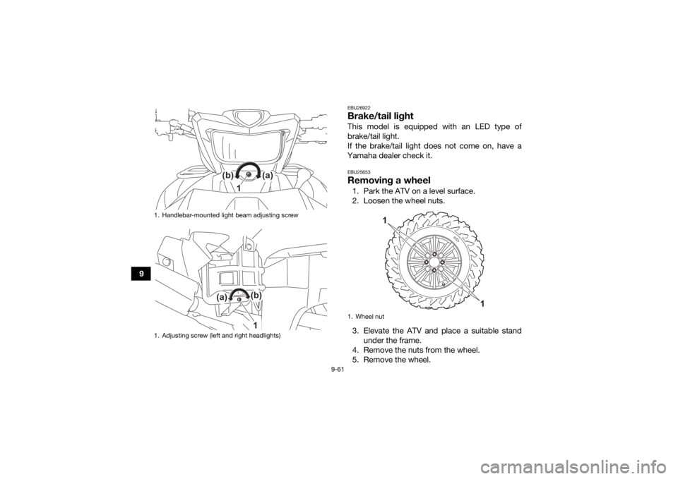
EBU25553Adjusting a headlight beamNOTICEECB00691It is advisable to have a Yamaha dealer make
this adjustment. To raise a headlight beam, turn the headlight
beam adjusting screw in direction (a).
To lower a headlight beam, turn the adjusting
screw in direction (b).
1. Do not touch the glass part of the bulb.
1
1. Handlebar-mounted light cover
1
UBFE60E0.book Page 60 Tuesday, August 18, 2020 10:50 AM
Page 160 of 178
9-61
9
EBU26922Brake/tail lightThis model is equipped with an LED type of
brake/tail light.
If the brake/tail light does not come on, have a
Yamaha dealer check it.EBU25653Removing a wheel1. Park the ATV on a level surface.
2. Loosen the wheel nuts.
3. Elevate the ATV and place a suitable stand under the frame.
4. Remove the nuts from the wheel.
5. Remove the wheel.
1. Handlebar-mounted light beam adjusting screw
1. Adjusting screw (left and right headlights)
(b)
(a)
1
(b)
(a)
1
1. Wheel nut
1
1
UBFE60E0.book Page 61 Tuesday, August 18, 2020 10:50 AM