9-2 YAMAHA KODIAK 700 2021 User Guide
[x] Cancel search | Manufacturer: YAMAHA, Model Year: 2021, Model line: KODIAK 700, Model: YAMAHA KODIAK 700 2021Pages: 176, PDF Size: 4.75 MB
Page 121 of 176
![YAMAHA KODIAK 700 2021 User Guide 9-26
9
5. Refill with the recommended final gear oil to
the brim of the check hole as shown.
NOTICE: Be sure no foreign material en-
ters the final gear case.
[ECB00422]
6. Check the oil level check YAMAHA KODIAK 700 2021 User Guide 9-26
9
5. Refill with the recommended final gear oil to
the brim of the check hole as shown.
NOTICE: Be sure no foreign material en-
ters the final gear case.
[ECB00422]
6. Check the oil level check](/img/51/50554/w960_50554-120.png)
9-26
9
5. Refill with the recommended final gear oil to
the brim of the check hole as shown.
NOTICE: Be sure no foreign material en-
ters the final gear case.
[ECB00422]
6. Check the oil level check bolt gasket and the oil filler bolt gasket for damage, and replace
them if necessary.
7. Install the oil level check bolt, the oil filler bolt and their gasket, and then tighten the bolts to
the specified torques.
8. Check the final gear case for oil leakage. If oil is leaking, check for the cause.EBU23429Differential gear oilThe differential gear case must be checked for oil
leakage before each ride. If any leakage is found,
have a Yamaha dealer check and repair the ATV.
In addition, the differential gear oil level must be
checked and the oil changed as follows at the in-
tervals specified in the periodic maintenance
chart.
Tightening torque:
Final gear oil drain bolt:23 N·m (2.3 kgf·m, 17 lb·ft)
1. Final gear oil
2. Gasket
3. Final gear oil level check bolt
4. Correct oil levelRecommended final gear oil: See page 11-1.
1
243
Tightening torquesWFinal gear oil level check bolt:10 N
Page 122 of 176

9-27
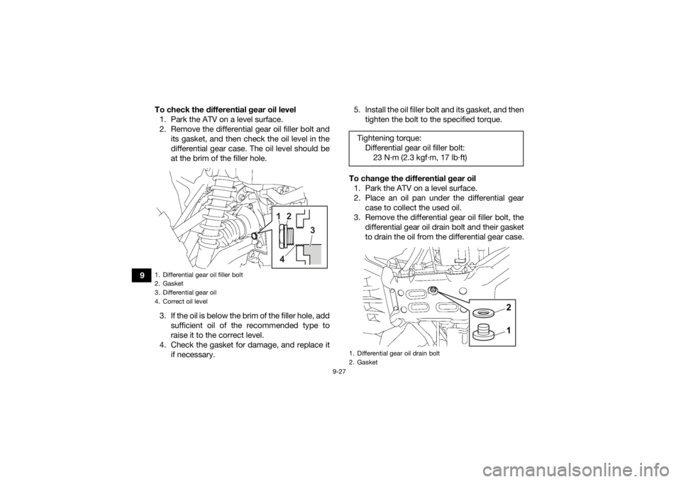
9To check the differential gear oil level
1. Park the ATV on a level surface.
2. Remove the differential gear oil filler bolt and its gasket, and then check the oil level in the
differential gear case. The oil level should be
at the brim of the filler hole.
3. If the oil is below the brim of the filler hole, add sufficient oil of the recommended type to
raise it to the correct level.
4. Check the gasket for damage, and replace it if necessary. 5. Install the oil filler bolt and its gasket, and then
tighten the bolt to the specified torque.
To change the differential gear oil 1. Park the ATV on a level surface.
2. Place an oil pan under the differential gear case to collect the used oil.
3. Remove the differential gear oil filler bolt, the differential gear oil drain bolt and their gasket
to drain the oil from the differential gear case.
1. Differential gear oil filler bolt
2. Gasket
3. Differential gear oil
4. Correct oil level
1
2
3
4
Tightening torque: Differential gear oil filler bolt:23 N
Page 123 of 176

9-28
9
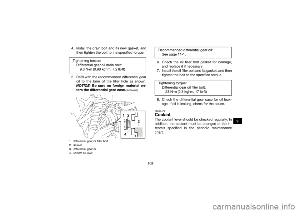
4. Install the drain bolt and its new gasket, and
then tighten the bolt to the specified torque.
5. Refill with the recommended differential gear oil to the brim of the filler hole as shown.
NOTICE: Be sure no foreign material en-
ters the differential gear case.
[ECB00412]
6. Check the oil filler bolt gasket for damage, and replace it if necessary.
7. Install the oil filler bolt and its gasket, and then tighten the bolt to the specified torque.
8. Check the differential gear case for oil leak- age. If oil is leaking, check for the cause.EBU23473CoolantThe coolant level should be checked regularly. In
addition, the coolant must be changed at the in-
tervals specified in the periodic maintenance
chart.
Tightening torque:
Differential gear oil drain bolt:9.8 N·m (0.98 kgf·m, 7.2 lb·ft)
1. Differential gear oil filler bolt
2. Gasket
3. Differential gear oil
4. Correct oil level
1
2
3
4
Recommended differential gear oil: See page 11-1.
Tightening torque: Differential gear oil filler bolt:23 N
Page 124 of 176

9-29
9
TIPIf genuine Yamaha coolant is not available, use an
ethylene glycol antifreeze containing corrosion in-
hibitors for aluminum engines and mix with dis-
tilled water at a 1:1 ratio. NOTICEECB02190Mix antifreeze with distilled water only. Howev-
er, if distilled water is not available, soft water
may be used for refilling. Do not use hard water
or salt water since they are harmful to the en-
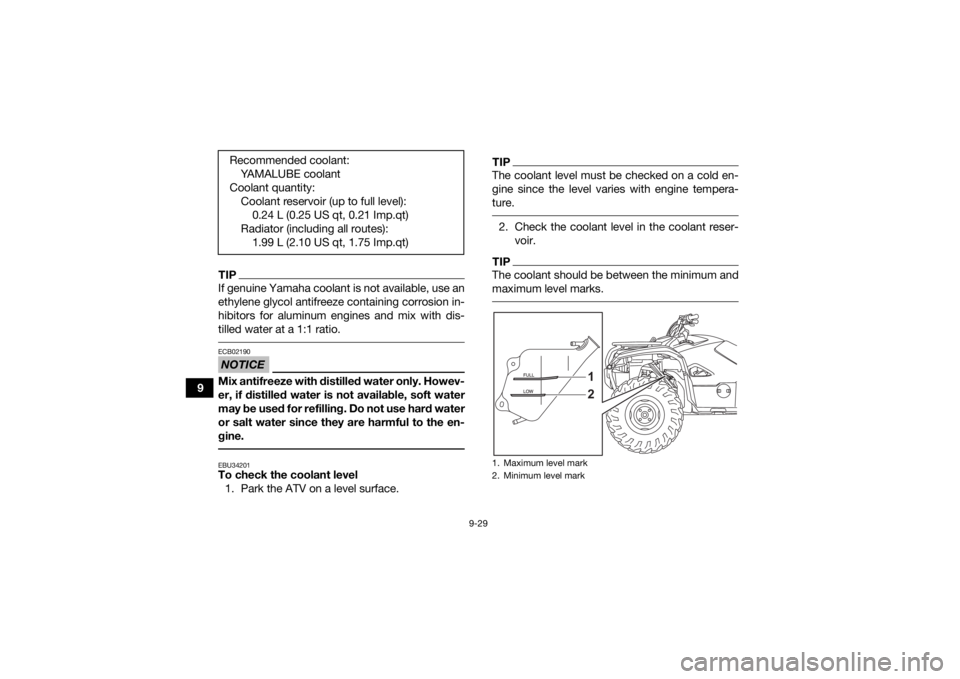
gine. EBU34201To check the coolant level1. Park the ATV on a level surface.
TIPThe coolant level must be checked on a cold en-
gine since the level varies with engine tempera-
ture. 2. Check the coolant level in the coolant reser- voir.TIPThe coolant should be between the minimum and
maximum level marks.
Recommended coolant:YAMALUBE coolant
Coolant quantity: Coolant reservoir (up to full level):0.24 L (0.25 US qt, 0.21 Imp.qt)
Radiator (including all routes): 1.99 L (2.10 US qt, 1.75 Imp.qt)
1. Maximum level mark
2. Minimum level mark
12
UB5K63E0.book Page 29 Monday, October 12, 2020 4:59 PM
Page 173 of 176

13-1
13
INDEX
AAccessories and loading ................................................ 7-5
Accessories, DC jack ................................................... 5-30
Air filter element, cleaning ........................................... 9-36
Axle boots .................................................................... 9-47BBattery ......................................................................... 9-53
Battery voltage warning light ......................................... 5-3
Brake fluid, changing ................................................... 9-44
Brake fluid level, checking ........................................... 9-43
Brake lever free play, checking the front ..................... 9-44
Brake lever, front ......................................................... 5-19
Brake levers, checking and lubricating ........................ 9-49
Brake light switches ..................................................... 9-48
Brake pads and friction plates, checking .................... 9-42
Brake pedal and rear brake lever ................................. 5-20
Brake pedal, checking and lubricating ........................ 9-50
Brakes .......................................................................... 9-41
Brakes, front and rear .................................................... 6-3
Brake/tail light bulb, replacing ..................................... 9-63CCables, checking and lubricating ................................ 9-48
Carrier, front ................................................................. 5-26
Carrier, rear .................................................................. 5-26
Chassis fasteners .......................................................... 6-7
Cleaning ....................................................................... 10-1
Coolant .................................................................6-3, 9-28
Coolant temperature warning light ................................ 5-3
DDifferential gear lock, indicators (YFM700FWBD) ......... 5-5
Differential gear oil ................................................6-3, 9-26
Drive lever 2WD/4WD (YFM700FWB) .......................... 5-17
Drive select lever ......................................................... 5-21
Drive select lever and driving in reverse ........................ 7-2EEmissions Certification label (for Europe) .................... 12-1
Engine break-in .............................................................. 7-4
Engine oil ....................................................................... 6-3
Engine oil and oil filter cartridge .................................. 9-19
Engine stop switch ...................................................... 5-13
Engine trouble warning light .......................................... 5-4
EPS warning light (YFM700FWBD) ................................ 5-4FFinal gear oil ......................................................... 6-3, 9-24
Four-wheel drive icon (YFM700FWBD) ......................... 5-5
Four-wheel drive indicator light (YFM700FWB) ............. 5-5
Four-wheel drive switch (On-Command 4WD) (YFM700FWBD) ......................................................... 5-15
Fuel ....................................................................... 5-22, 6-3
Fuel level warning light (YFM700FWB) .......................... 5-4
Fuel tank cap ............................................................... 5-21
Fuses, replacing .......................................................... 9-56HHandlebar switches ..................................................... 5-12
Headlight beam, adjusting ........................................... 9-62
Headlight bulb, replacing ............................................. 9-59
High beam indicator light ............................................... 5-3
UB5K63E0.book Page 1 Monday, October 12, 2020 4:59 PM
Page 174 of 176

13-2
13
High-range indicator light (YFM700FWBD) .................... 5-2
Horn switch .................................................................. 5-13IIdentification numbers ................................................... 1-1
Indicator lights and warning lights ................................. 5-1
Instruments, lights and switches ................................... 6-7LLabel locations ............................................................... 2-1
Light switch .................................................................. 5-13
Low-range indicator light (YFM700FWBD) .................... 5-2MMain switch .................................................................... 5-1
Maintenance chart, emission control system ................ 9-3
Maintenance chart, general maintenance and lubrication .................................................................... 9-5
Model label ..................................................................... 1-1
Multi-function display .....................................................5-6NNeutral indicator light .....................................................5-2OOn-Command drive switch “4WD/LOCK”
(YFM700FWBD) ......................................................... 5-15
Override switch (YFM700FWBD) ................................. 5-14
Owner’s Manuals and Tool Kit ....................................... 9-2PPanels, removing and installing ..................................... 9-9
Park indicator light ......................................................... 5-2
Parking ........................................................................... 7-4
Parking on a slope ......................................................... 7-5
Part locations ................................................................. 4-1
RRear brake, adjusting the lever, pedal free play .......... 9-44
Rear knuckle pivots, lubricating ................................... 9-51
Reverse indicator light ................................................... 5-2
Riding your ATV ............................................................. 8-1SSafety information .......................................................... 3-1
Seat .............................................................................. 5-24
Shock absorber assemblies, adjusting the front and
rear (YFM700FWBD) .................................................. 5-26
Spark arrester, cleaning ............................................... 9-39
Spark plug, checking ................................................... 9-17
Specifications .............................................................. 11-1
Speed limiter ................................................................ 5-19
Stabilizer bushes, checking ......................................... 9-51
Starting the engine ......................................................... 7-1
Start switch .................................................................. 5-13
Steering shaft, lubricating ............................................ 9-52
Storage ........................................................................ 10-2
Storage compartment .................................................. 5-25TThrottle lever ........................................................ 5-18, 6-4
Throttle lever free play, adjusting ................................. 9-41
Tires ............................................................................... 6-4
Trailer hitch .................................................................. 5-29
Troubleshooting ........................................................... 9-65
Troubleshooting charts ................................................ 9-66VValve clearance ............................................................ 9-41
V-belt case drain plug .................................................. 9-40
Vehicle identification number ......................................... 1-1
UB5K63E0.book Page 2 Monday, October 12, 2020 4:59 PM
Page 175 of 176

13-3
13
WWheel hub bearings, checking .................................... 9-50
Wheel, installing ........................................................... 9-64
Wheel, removing .......................................................... 9-64
Winch ........................................................................... 5-28
Winch switch ............................................................... 5-14YYamalube ..................................................................... 9-23
UB5K63E0.book Page 3 Monday, October 12, 2020 4:59 PM