ABS YAMAHA MAJESTY 250 2002 Owners Manual
[x] Cancel search | Manufacturer: YAMAHA, Model Year: 2002, Model line: MAJESTY 250, Model: YAMAHA MAJESTY 250 2002Pages: 114, PDF Size: 1.96 MB
Page 13 of 114
2-1
EAU00026
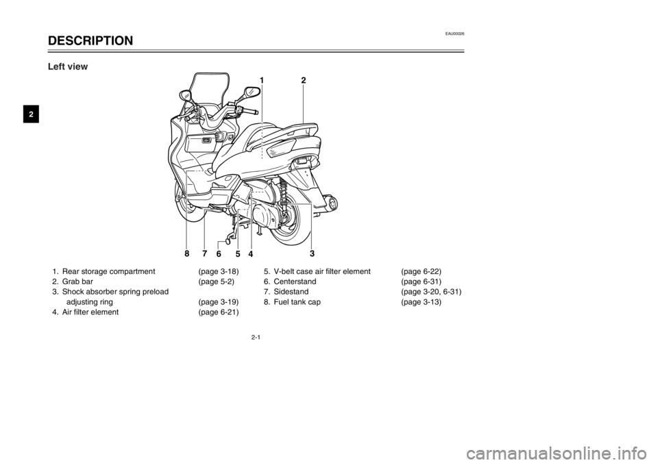
DESCRIPTIONPart locations
2
1. Rear storage compartment (page 3-18)
2. Grab bar (page 5-2)
3. Shock absorber spring preload
adjusting ring (page 3-19)
4. Air filter element (page 6-21)5. V-belt case air filter element (page 6-22)
6. Centerstand (page 6-31)
7. Sidestand (page 3-20, 6-31)
8. Fuel tank cap (page 3-13)
12
3
4 5 6 7
8
Left view
5SJ-28199-E0 1/24/02 6:14 PM Page 12
Page 16 of 114
INSTRUMENT AND CONTROL FUNCTIONSMain switch/steering lock ...................................................................3-1
Indicator lights ...................................................................................3-2
Speedometer .....................................................................................3-3
Tachometer .......................................................................................3-3
Fuel gauge .........................................................................................3-4
Coolant temperature gauge ...............................................................3-5
Multi-function display .........................................................................3-5
Anti-theft alarm (optional) ..................................................................3-9
Handlebar switches .........................................................................3-10
Front brake lever .............................................................................3-12
Rear brake lever ..............................................................................3-13
Fuel tank cap ...................................................................................3-13
Fuel ..................................................................................................3-14
Catalytic converter ...........................................................................3-15
Rider seat ........................................................................................3-16
Adjusting the rider seat ....................................................................3-17
Storage compartments ....................................................................3-17
Adjusting the shock absorber assemblies .......................................3-19
Sidestand .........................................................................................3-20
Ignition circuit cut-off system ...........................................................3-21
3
5SJ-28199-E0 1/24/02 6:14 PM Page 15
Page 35 of 114
3-19
INSTRUMENT AND CONTROL FUNCTIONS
3
ECA00051
cCDo not leave the rider seat open
for an extended period of time,
otherwise the light may cause the
battery to discharge.
EWA00035
wDo not exceed the following load-
ing limits:
8 8
Front storage compartment A:
2 kg
8 8
Rear storage compartment:
5 kg
8 8
Maximum load for the vehicle:
185 kg
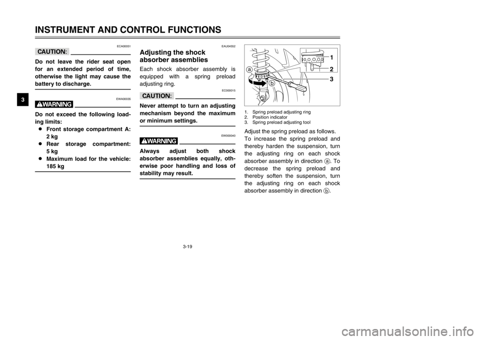
Adjust the spring preload as follows.
To increase the spring preload and
thereby harden the suspension, turn
the adjusting ring on each shock
absorber assembly in direction a. To
decrease the spring preload and
thereby soften the suspension, turn
the adjusting ring on each shock
absorber assembly in direction b.a
b1
23
1. Spring preload adjusting ring
2. Position indicator
3. Spring preload adjusting tool
EAU04552
Adjusting the shock
absorber assembliesShock absorber assemblies, adjustingEach shock absorber assembly is
equipped with a spring preload
adjusting ring.
EC000015
cCNever attempt to turn an adjusting
mechanism beyond the maximum
or minimum settings.
EW000040
wAlways adjust both shock
absorber assemblies equally, oth-
erwise poor handling and loss of
stability may result.
5SJ-28199-E0 1/24/02 6:14 PM Page 34
Page 36 of 114

3-20
INSTRUMENT AND CONTROL FUNCTIONS
3
NOTE:
8Align the appropriate notch in the
adjusting ring with the position
indicator on the shock absorber.
8Use the spring preload adjusting
tool included in the owner’s tool
kit to make this adjustment.
EAU00330
SidestandSidestandThe sidestand is located on the left
side of the frame. Raise the side-
stand or lower it with your foot while
holding the scooter upright.NOTE:
The built-in sidestand switch is part of
the ignition circuit cut-off system,
which cuts the ignition in certain situ-
ations. (See further down for an
explanation of the ignition circuit cut-
off system.)
1
1. Sidestand switch
EW000044
wThe scooter must not be ridden
with the sidestand down, or if the
sidestand cannot be properly
moved up (or does not stay up),
otherwise the sidestand could con-
tact the ground and distract the
operator, resulting in a possible
loss of control. Yamaha’s ignition
circuit cut-off system has been
designed to assist the operator in
fulfilling the responsibility of rais-
ing the sidestand before starting
off. Therefore, check this system
regularly as described below and
have a Yamaha dealer repair it if it
does not function properly.
Setting
Minimum (soft) 1
Standard 4
Maximum (hard) 7
5SJ-28199-E0 1/24/02 6:14 PM Page 35
Page 54 of 114

6-4
PERIODIC MAINTENANCE AND MINOR REPAIR
6
8
*Brake hoses•Check for cracks or damage.√√√√ √
•Replace. (See NOTE on page 6-5.)Every 4 years
9*Wheels•Check runout and for damage.√√√√
10*Tires•Check tread depth and for damage.
•Replace if necessary.
•Check air pressure.
•Correct if necessary.√√√√ √
11*Wheel bearings•Check bearing for looseness or damage.√√√√
12*Steering bearings•Check bearing play and steering for roughness.√√√√√
•Lubricate with lithium-soap-based grease.Every 20,000 km
13*Chassis fasteners•Make sure that all nuts, bolts and screws are properly tightened.√√√√ √
14 Sidestand, centerstand•Check operation.
•Lubricate.√√√√ √
15*Sidestand switch•Check operation.√√√√√ √
16*Front fork•Check operation and for oil leakage.√√√√
17*Shock absorber
assemblies•Check operation and shock absorbers for oil leakage.√√√√
18*Carburetor•Adjust engine idling speed.√√√√√ √
19 Engine oil•Change. (See page 3-2 and 6-17 for more information
about the oil change indicator light.)√When the oil change indicator light comes on
(every 3,000 km)
•Check oil level and vehicle for oil leakage.Every 3,000 km√ NO. ITEM CHECK OR MAINTENANCE JOBODOMETER READING (× 1,000 km)
ANNUAL
CHECK
1 10203040
5SJ-28199-E0 1/24/02 6:14 PM Page 53
Page 58 of 114
6-8
PERIODIC MAINTENANCE AND MINOR REPAIR
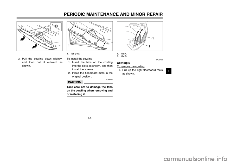
6 3. Pull the cowling down slightly,
and then pull it outward as
shown.
EAU03632
Cowling B
To remove the cowling1. Pull up the right floorboard mats
as shown.
1
2
1. Mat A
2. Mat B
To install the cowling1. Insert the tabs on the cowling
into the slots as shown, and then
install the screws.
2. Place the floorboard mats in the
original position.
ECA00067
cCTake care not to damage the tabs
on the cowling when removing and
or installing it.11. Tab (×10)
5SJ-28199-E0 1/24/02 6:14 PM Page 57
Page 59 of 114
6-9
PERIODIC MAINTENANCE AND MINOR REPAIR
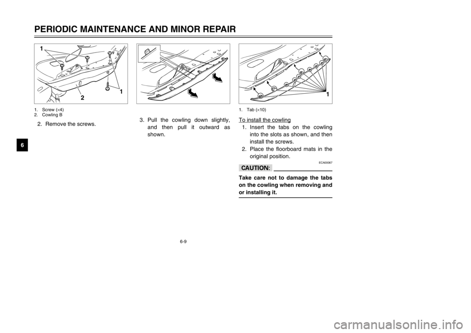
62. Remove the screws.
2 1
1
1. Screw (×4)
2. Cowling B
To install the cowling1. Insert the tabs on the cowling
into the slots as shown, and then
install the screws.
2. Place the floorboard mats in the
original position.
ECA00067
cCTake care not to damage the tabs
on the cowling when removing and
or installing it.
1
1. Tab (×10)
3. Pull the cowling down slightly,
and then pull it outward as
shown.
5SJ-28199-E0 1/24/02 6:14 PM Page 58
Page 60 of 114
6-10
PERIODIC MAINTENANCE AND MINOR REPAIR
6
EAU03617
Cowling C
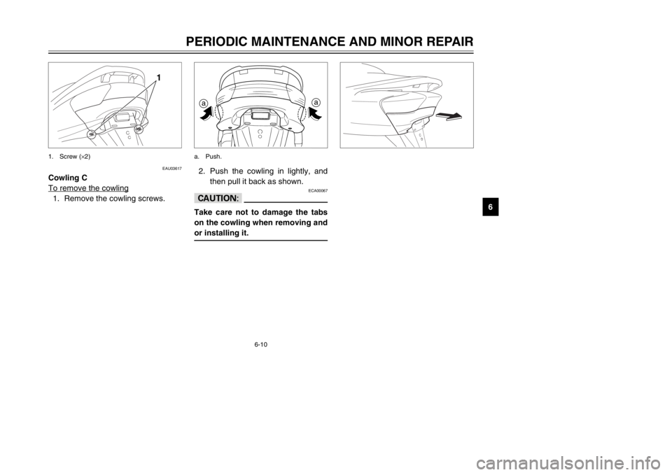
To remove the cowling1. Remove the cowling screws.
1
1. Screw (×2)
2. Push the cowling in lightly, and
then pull it back as shown.
ECA00067
cCTake care not to damage the tabs
on the cowling when removing and
or installing it.aaa. Push.
5SJ-28199-E0 1/24/02 6:14 PM Page 59
Page 61 of 114
6-11
PERIODIC MAINTENANCE AND MINOR REPAIR
6To install the cowling
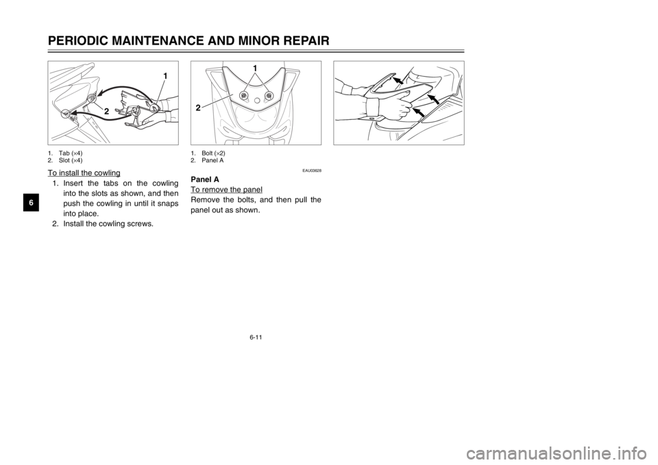
1. Insert the tabs on the cowling
into the slots as shown, and then
push the cowling in until it snaps
into place.
2. Install the cowling screws.
1
2
1. Tab (×4)
2. Slot (×4)
EAU03628
Panel A
To remove the panelRemove the bolts, and then pull the
panel out as shown.
1
2
1. Bolt (×2)
2. Panel A
5SJ-28199-E0 1/24/02 6:14 PM Page 60
Page 99 of 114

7-3
SCOOTER CARE AND STORAGE
7After cleaning
1. Dry the scooter with a chamois
or an absorbing cloth.
2. Use a chrome polish to shine
chrome, aluminum and stainless-
steel parts, including the exhaust
system. (Even the thermally
induced discoloring of stainless-
steel exhaust systems can be
removed through polishing.)
3. To prevent corrosion, it is recom-
mended to apply a corrosion pro-
tection spray on all metal, includ-
ing chrome- and nickel-plated,
surfaces.
4. Use spray oil as a universal
cleaner to remove any remaining
dirt.
5. Touch up minor paint damage
caused by stones, etc.6. Wax all painted surfaces.
7. Let the scooter dry completely
before storing or covering it.
EWA00002
w8Make sure that there is no oil
or wax on the brakes or tires.
If necessary, clean the brake
discs and brake linings with a
regular brake disc cleaner or
acetone, and wash the tires
with warm water and a mild
detergent.
8Before operating the scooter
test its braking performance
and cornering behavior.
ECA00013
cC8Apply spray oil and wax spar-
ingly and make sure to wipe
off any excess.
8Never apply oil or wax to any
rubber and plastic parts, but
treat them with a suitable care
product.
8Avoid using abrasive polish-
ing compounds as they will
wear away the paint.NOTE:
Consult a Yamaha dealer for advice
on what products to use.
5SJ-28199-E0 1/24/02 6:14 PM Page 98