air filter YAMAHA MT-03 2020 Owners Manual
[x] Cancel search | Manufacturer: YAMAHA, Model Year: 2020, Model line: MT-03, Model: YAMAHA MT-03 2020Pages: 94, PDF Size: 6.88 MB
Page 5 of 94

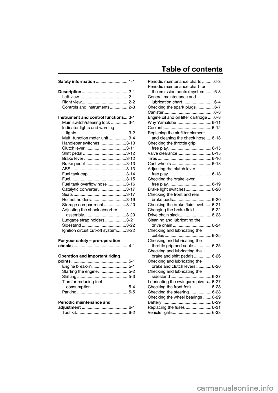
Table of contents
Safety information............................1-1
Description........................................2-1
Left view ..........................................2-1
Right view........................................2-2
Controls and instruments ................2-3
Instrument and control functions....3-1
Main switch/steering lock ...............3-1
Indicator lights and warning
lights ............................................3-2
Multi-function meter unit .................3-4
Handlebar switches.......................3-10
Clutch lever ...................................3-11
Shift pedal .....................................3-12
Brake lever ....................................3-12
Brake pedal ...................................3-13
ABS ...............................................3-13
Fuel tank cap.................................3-14
Fuel................................................3-15
Fuel tank overflow hose ................3-16
Catalytic converter ........................3-17
Seats .............................................3-17
Helmet holders ..............................3-19
Storage compartment ...................3-20
Adjusting the shock absorber
assembly....................................3-20
Luggage strap holders ..................3-21
Sidestand ......................................3-22
Ignition circuit cut-off system........3-22
For your safety – pre-operation
checks...............................................4-1
Operation and important riding
points.................................................5-1
Engine break-in ...............................5-1
Starting the engine ..........................5-2
Shifting ............................................5-3
Tips for reducing fuel
consumption ................................5-4
Parking ............................................5-5
Periodic maintenance and
adjustment........................................6-1
Tool kit.............................................6-2Periodic maintenance charts .......... 6-3
Periodic maintenance chart for
the emission control system........ 6-3
General maintenance and
lubrication chart........................... 6-4
Checking the spark plugs ............... 6-7
Canister........................................... 6-8
Engine oil and oil filter cartridge ..... 6-8
Why Yamalube .............................. 6-11
Coolant ......................................... 6-12
Replacing the air filter element
and cleaning the check hose..... 6-13
Checking the throttle grip
free play ..................................... 6-15
Valve clearance ............................. 6-15
Tires .............................................. 6-16
Cast wheels .................................. 6-18
Adjusting the clutch lever
free play ..................................... 6-18
Checking the brake lever
free play ..................................... 6-19
Brake light switches ...................... 6-20
Checking the front and rear
brake pads................................. 6-20
Checking the brake fluid level....... 6-21
Changing the brake fluid............... 6-22
Drive chain slack ........................... 6-23
Cleaning and lubricating the
drive chain ................................. 6-24
Checking and lubricating the
cables ........................................ 6-25
Checking and lubricating the
throttle grip and cable ............... 6-25
Checking and lubricating the
brake and shift pedals ............... 6-26
Checking and lubricating the
brake and clutch levers ............. 6-26
Checking and lubricating the
sidestand ................................... 6-27
Lubricating the swingarm pivots... 6-27
Checking the front fork ................. 6-28
Checking the steering ................... 6-28
Checking the wheel bearings ....... 6-29
Battery .......................................... 6-29
Replacing the fuses ...................... 6-31
Vehicle lights ................................. 6-33
UB6WE0E0.book Page 1 Friday, March 27, 2020 11:37 AM
Page 48 of 94

Periodic maintenance and adjustment
6-4
6
EAU71372
General maintenance and lubrication chart
NO. ITEM
1*Diagnostic system
check• Perform dynamic inspection
using Yamaha diagnostic tool.
• Check the error codes.√√√√√√
2*Air filter element• Replace.√√
3Air filter case
check hose• Clean.√√√√√
4Clutch• Check operation.
•Adjust.√√√√√
5*Front brake• Check operation, fluid level,
and for fluid leakage.
• Replace brake pads if neces-
sary.√√√√√√
6*Rear brake• Check operation, fluid level,
and for fluid leakage.
• Replace brake pads if neces-
sary.√√√√√√
7*Brake hoses• Check for cracks or damage.√√√√√
• Replace. Every 4 years
8*Brake fluid• Change. Every 2 years
9*Wheels• Check runout and for damage.
• Replace if necessary.√√√√
10*Tires• Check tread depth and for
damage.
• Replace if necessary.
• Check air pressure.
• Correct if necessary.√√√√√
11*Wheel bearings• Check bearing for looseness or
damage.√√√√
12*Swingarm pivot
bearings• Check operation and for exces-
sive play.√√√√
13 Drive chain• Check chain slack, alignment
and condition.
• Adjust and lubricate chain with
a special O-ring chain lubricant
thoroughly.Every 800 km (500 mi) and after
washing the motorcycle, riding
in the rain or riding in wet areasX 1000 km CHECK OR
MAINTENANCE JOB
X 1000 miODOMETER
READINGSANNUAL CHECK
1 10203040
0.6 6 12 18 24
UB6WE0E0.book Page 4 Friday, March 27, 2020 11:37 AM
Page 50 of 94

Periodic maintenance and adjustment
6-6
6
EAU72710
TIP
Air filter
• This model’s air intake system is equipped with a disposable oil-coated pa-
per element. The air filter element cannot be cleaned with compressed air,
it must be replaced.
• The air filter element needs to be replaced more frequently when riding in
unusually wet or dusty areas.
Hydraulic brake service
• After disassembling the brake master cylinder and caliper, always change
the fluid. Regularly check the brake fluid level and fill the reservoir as re-
quired.
• Every two years replace the internal components of the brake master cyl-
inder and caliper, and change the brake fluid.
• Replace the brake hose every four years and if cracked or damaged.
28*Moving parts and
cables• Lubricate.√√√√√
29*Throttle grip hous-
ing and cable• Check operation and free play.
• Adjust the throttle cable free
play if necessary.
• Lubricate the throttle grip hous-
ing and cable.√√√√√
30*Lights, signals and
switches• Check operation.
• Adjust headlight beam.√√√√√√ NO. ITEM
X 1000 km CHECK OR
MAINTENANCE JOB
X 1000 miODOMETER
READINGS
ANNUAL CHECK
110203040
0.6 6 12 18 24
UB6WE0E0.book Page 6 Friday, March 27, 2020 11:37 AM
Page 57 of 94

Periodic maintenance and adjustment
6-13
6 4. Install the reservoir cap, and then
install the coolant reservoir cover
by installing the bolts.EAU33032Changing the coolant
The coolant must be changed at the in-
tervals specified in the periodic mainte-
nance and lubrication chart. Have a
Yamaha dealer change the coolant.
WARNING! Never attempt to remove
the radiator cap when the engine is
hot.
[EWA10382]EAUN1172
Replacing the air filter ele-
ment and cleaning the check
hose
The air filter element should be re-
placed at the intervals specified in the
periodic maintenance and lubrication
chart. Replace the air filter element
more frequently if you are riding in un-
usually wet or dusty areas. In addition,
the air filter check hose must be fre-
quently checked and cleaned if neces-
sary.
To replace the air filter element
1. Remove the rider seat. (See page
3-17.)
2. Remove the left side panel bolts.
3. Remove the left side panel by re-
moving the lower projection on the
panel from the slot, and then re-
moving the upper projection as
shown.
1. Coolant reservoir cap
Coolant reservoir capacity (up to
the maximum level mark):
0.25 L (0.26 US qt, 0.22 Imp.qt)
1
1. Left side panel
2. Bolt
2 1
UB6WE0E0.book Page 13 Friday, March 27, 2020 11:37 AM
Page 58 of 94

Periodic maintenance and adjustment
6-14
64. Lift up the rubber covers, and then
remove the air filter case cover by
removing the screws.
5. Pull the air filter element out.
6. Insert a new air filter element into
the air filter case. NOTICE: Make
sure that the air filter element is
properly seated in the air filtercase. The engine should never
be operated without the air filter
element installed, otherwise the
piston(s) and/or cylinder(s) may
become excessively worn.
[ECA10482]
7. Install the air filter case cover by
installing the screws, and then
place the rubber covers in their
original positions.
8. Place the left side panel in the
original position, and then install
the bolts.
9. Install the rider seat.
To clean the air filter check hose
1. Check the hose on the front of the
air filter case for accumulated dirt
or water.
2. If dirt or water is visible, remove
the hose, clean it, and then install
it.
1. Projection
1. Air filter case cover
2. Screw
3. Rubber cover
1. Air filter element
1
12
23
1
1. Air filter check hose
1
UB6WE0E0.book Page 14 Friday, March 27, 2020 11:37 AM
Page 91 of 94

10-1
10
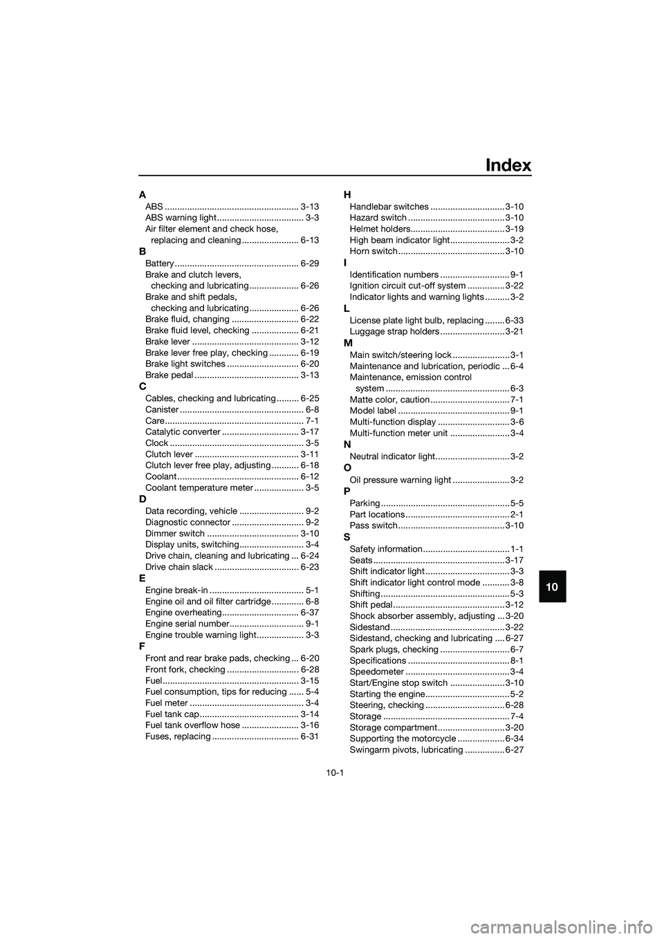
Index
A
ABS ...................................................... 3-13
ABS warning light ................................... 3-3
Air filter element and check hose,
replacing and cleaning ....................... 6-13
B
Battery .................................................. 6-29
Brake and clutch levers,
checking and lubricating .................... 6-26
Brake and shift pedals,
checking and lubricating .................... 6-26
Brake fluid, changing ........................... 6-22
Brake fluid level, checking ................... 6-21
Brake lever ........................................... 3-12
Brake lever free play, checking ............ 6-19
Brake light switches ............................. 6-20
Brake pedal .......................................... 3-13
C
Cables, checking and lubricating ......... 6-25
Canister .................................................. 6-8
Care ........................................................ 7-1
Catalytic converter ............................... 3-17
Clock ...................................................... 3-5
Clutch lever .......................................... 3-11
Clutch lever free play, adjusting ........... 6-18
Coolant ................................................. 6-12
Coolant temperature meter .................... 3-5
D
Data recording, vehicle .......................... 9-2
Diagnostic connector ............................. 9-2
Dimmer switch ..................................... 3-10
Display units, switching.......................... 3-4
Drive chain, cleaning and lubricating ... 6-24
Drive chain slack .................................. 6-23
E
Engine break-in ...................................... 5-1
Engine oil and oil filter cartridge ............. 6-8
Engine overheating............................... 6-37
Engine serial number.............................. 9-1
Engine trouble warning light................... 3-3
F
Front and rear brake pads, checking ... 6-20
Front fork, checking ............................. 6-28
Fuel....................................................... 3-15
Fuel consumption, tips for reducing ...... 5-4
Fuel meter .............................................. 3-4
Fuel tank cap........................................ 3-14
Fuel tank overflow hose ....................... 3-16
Fuses, replacing ................................... 6-31
H
Handlebar switches .............................. 3-10
Hazard switch ....................................... 3-10
Helmet holders...................................... 3-19
High beam indicator light........................ 3-2
Horn switch........................................... 3-10
I
Identification numbers ............................ 9-1
Ignition circuit cut-off system ............... 3-22
Indicator lights and warning lights .......... 3-2
L
License plate light bulb, replacing ........ 6-33
Luggage strap holders .......................... 3-21
M
Main switch/steering lock ....................... 3-1
Maintenance and lubrication, periodic ... 6-4
Maintenance, emission control
system .................................................. 6-3
Matte color, caution ................................ 7-1
Model label ............................................. 9-1
Multi-function display ............................. 3-6
Multi-function meter unit ........................ 3-4
N
Neutral indicator light.............................. 3-2
O
Oil pressure warning light ....................... 3-2
P
Parking .................................................... 5-5
Part locations .......................................... 2-1
Pass switch........................................... 3-10
S
Safety information................................... 1-1
Seats ..................................................... 3-17
Shift indicator light .................................. 3-3
Shift indicator light control mode ........... 3-8
Shifting .................................................... 5-3
Shift pedal............................................. 3-12
Shock absorber assembly, adjusting ... 3-20
Sidestand .............................................. 3-22
Sidestand, checking and lubricating .... 6-27
Spark plugs, checking ............................ 6-7
Specifications ......................................... 8-1
Speedometer .......................................... 3-4
Start/Engine stop switch ...................... 3-10
Starting the engine.................................. 5-2
Steering, checking ................................ 6-28
Storage ................................................... 7-4
Storage compartment ........................... 3-20
Supporting the motorcycle ................... 6-34
Swingarm pivots, lubricating ................ 6-27
UB6WE0E0.book Page 1 Friday, March 27, 2020 11:37 AM