torque YAMAHA MT-09 2016 Owners Manual
[x] Cancel search | Manufacturer: YAMAHA, Model Year: 2016, Model line: MT-09, Model: YAMAHA MT-09 2016Pages: 114, PDF Size: 4.24 MB
Page 57 of 114
Periodic maintenance and adjustment
6-2
1
2
3
4
567
8
9
10
11
12
EAU39692
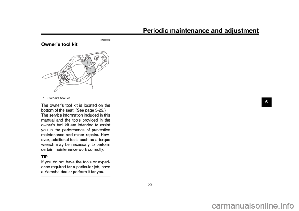
Owner’s tool kitThe owner’s tool kit is located on the
bottom of the seat. (See page 3-25.)
The service information included in this
manual and the tools provided in the
owner’s tool kit are intended to assist
you in the performance of preventive
maintenance and minor repairs. How-
ever, additional tools such as a torque
wrench may be necessary to perform
certain maintenance work correctly.TIPIf you do not have the tools or experi-
ence required for a particular job, havea Yamaha dealer perform it for you.1. Owner’s tool kit
1
B87-9-E0_1.book 2 ページ 2015年12月16日 水曜日 午前10時21分
Page 63 of 114

Periodic maintenance and adjustment
6-8
1
2
3
4
567
8
9
10
11
12
EAU19653
Checking the spark plugsThe spark plugs are important engine
components, which should be checked
periodically, preferably by a Yamaha
dealer. Since heat and deposits will
cause any spark plug to slowly erode,
they should be removed and checked
in accordance with the periodic mainte-
nance and lubrication chart. In addition,
the condition of the spark plugs can re-
veal the condition of the engine.
The porcelain insulator around the cen-
ter electrode of each spark plug should
be a medium-to-light tan (the ideal color
when the vehicle is ridden normally),
and all spark plugs installed in the en-
gine should have the same color. If any
spark plug shows a distinctly different
color, the engine could be operating im-
properly. Do not attempt to diagnose
such problems yourself. Instead, have
a Yamaha dealer check the vehicle.
If a spark plug shows signs of electrode
erosion and excessive carbon or other
deposits, it should be replaced. Before installing a spark plug, the spark
plug gap should be measured with a
wire thickness gauge and, if necessary,
adjusted to specification.
Clean the surface of the spark plug
gasket and its mating surface, and then
wipe off any grime from the spark plug
threads.
TIPIf a torque wrench is not available wheninstalling a spark plug, a good estimate
of the correct torque is 1/4–1/2 turn
past finger tight. However, the spark
plug should be tightened to the speci-
fied torque as soon as possible.NOTICE
ECA10841
Do not use any tools to remove or in-
stall the spark plug cap, otherwise
the ignition coil coupler may get
damaged. The spark plug cap may
be difficult to remove because the
rubber seal on the end of the cap fits
tightly. To remove the spark plug
cap, simply twist it back and forth
while pulling it out; to install it, twistit back and forth while pushing it in.
Specified spark plug:
NGK/CPR9EA9
1. Spark plug gapSpark plug gap:0.8–0.9 mm (0.031–0.035 in)
Tightening torque: Spark plug:13 Nm (1.3 m·kgf, 9.4 ft·lbf)
B87-9-E0_1.book 8 ページ 2015年12月16日 水曜日 午前10時21分
Page 65 of 114
Periodic maintenance and adjustment6-10
1
2
3
4
567
8
9
10
11
12
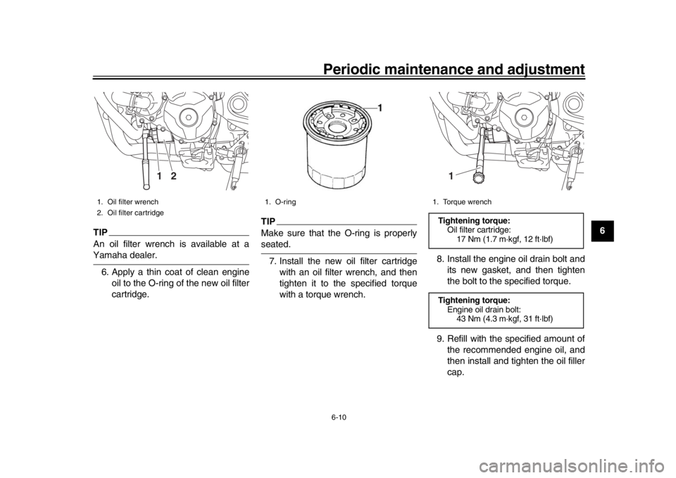
TIPAn oil filter wrench is available at aYamaha dealer. 6. Apply a thin coat of clean engine oil to the O-ring of the new oil filter
cartridge.
TIPMake sure that the O-ring is properlyseated.
7. Install the new oil filter cartridge with an oil filter wrench, and then
tighten it to the specified torque
with a torque wrench. 8. Install the engine oil drain bolt and
its new gasket, and then tighten
the bolt to the specified torque.
9. Refill with the specified amount of the recommended engine oil, and
then install and tighten the oil filler
cap.
1. Oil filter wrench
2. Oil filter cartridge
2
1
1. O-ring
1. Torque wrenchTightening torque:Oil filter cartridge:
17 Nm (1.7 m·kgf, 12 ft·lbf)
Tightening torque: Engine oil drain bolt:43 Nm (4.3 m·kgf, 31 ft·lbf)
1
B87-9-E0_1.book 10 ページ 2015年12月16日 水曜日 午前10時21分
Page 68 of 114
Periodic maintenance and adjustment
6-13
1
2
3
4
56
7
8
9
10
11
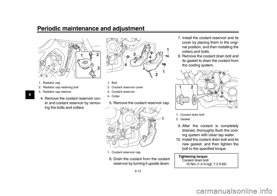
12 4. Remove the coolant reservoir cov-
er and coolant reservoir by remov-
ing the bolts and collars. 5. Remove the coolant reservoir cap.
6. Drain the coolant from the coolant
reservoir by turning it upside down. 7. Install the coolant reservoir and its
cover by placing them in the origi-
nal position, and then installing the
collars and bolts.
8. Remove the coolant drain bolt and its gasket to drain the coolant from
the cooling system.
9. After the coolant is completely drained, thoroughly flush the cool-
ing system with clean tap water.
10. Install the coolant drain bolt and its new gasket, and then tighten the
bolt to the specified torque.
1. Radiator cap
2. Radiator cap retaining bolt
3. Radiator cap retainer
2
1
3
1. Bolt
2. Coolant reservoir cover
3. Coolant reservoir
4. Collar
1. Coolant reservoir cap
1
1
2
4
3
4
1
1. Coolant drain bolt
2. GasketTightening torque:Coolant drain bolt:
10 Nm (1.0 m·kgf, 7.2 ft·lbf)1
2
B87-9-E0_1.book 13 ページ 2015年12月16日 水曜日 午前10時21分
Page 79 of 114
Periodic maintenance and adjustment6-24
1
2
3
4
567
8
9
10
11
12
EAU57971
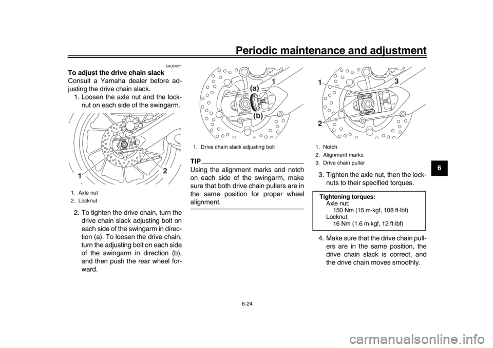
To adjust the drive chain slack
Consult a Yamaha dealer before ad-
justing the drive chain slack. 1. Loosen the axle nut and the lock- nut on each side of the swingarm.
2. To tighten the drive chain, turn the drive chain slack adjusting bolt on
each side of the swingarm in direc-
tion (a). To loosen the drive chain,
turn the adjusting bolt on each side
of the swingarm in direction (b),
and then push the rear wheel for-
ward.
TIPUsing the alignment marks and notch
on each side of the swingarm, make
sure that both drive chain pullers are in
the same position for proper wheelalignment. 3. Tighten the axle nut, then the lock-
nuts to their specified torques.
4. Make sure that the drive chain pull- ers are in the same position, the
drive chain slack is correct, and
the drive chain moves smoothly.
1. Axle nut
2. Locknut
2
1
1. Drive chain slack adjusting bolt
(a)(b)
1
1. Notch
2. Alignment marks
3. Drive chain pullerTightening torques:Axle nut:150 Nm (15 m·kgf, 108 ft·lbf)
Locknut:
16 Nm (1.6 m·kgf, 12 ft·lbf)
3
12
B87-9-E0_1.book 24 ページ 2015年12月16日 水曜日 午前10時21分
Page 95 of 114
Periodic maintenance and adjustment6-40
1
2
3
4
567
8
9
10
11
12
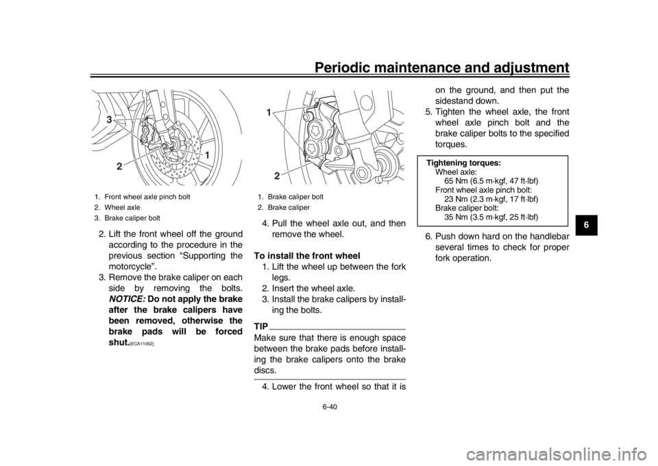
2. Lift the front wheel off the ground
according to the procedure in the
previous section “Supporting the
motorcycle”.
3. Remove the brake caliper on each side by removing the bolts.
NOTICE: Do not apply the brake
after the brake calipers have
been removed, otherwise the
brake pads will be forced
shut.
[ECA11052]
4. Pull the wheel axle out, and then remove the wheel.
To install the front wheel 1. Lift the wheel up between the fork legs.
2. Insert the wheel axle.
3. Install the brake calipers by install- ing the bolts.TIPMake sure that there is enough space
between the brake pads before install-
ing the brake calipers onto the brakediscs.
4. Lower the front wheel so that it is on the ground, and then put the
sidestand down.
5. Tighten the wheel axle, the front wheel axle pinch bolt and the
brake caliper bolts to the specified
torques.
6. Push down hard on the handlebar several times to check for proper
fork operation.
1. Front wheel axle pinch bolt
2. Wheel axle
3. Brake caliper bolt
3
2
1
1. Brake caliper bolt
2. Brake caliper12
Tightening torques:Wheel axle:65 Nm (6.5 m·kgf, 47 ft·lbf)
Front wheel axle pinch bolt: 23 Nm (2.3 m·kgf, 17 ft·lbf)
Brake caliper bolt:
35 Nm (3.5 m·kgf, 25 ft·lbf)
B87-9-E0_1.book 40 ページ 2015年12月16日 水曜日 午前10時21分
Page 97 of 114
![YAMAHA MT-09 2016 Owners Manual Periodic maintenance and adjustment6-42
1
2
3
4
567
8
9
10
11
12
have been removed, otherwise
the brake pads will be forced
shut.
[ECA11073]
To install the rear wheel
1. Install the wheel and the brak YAMAHA MT-09 2016 Owners Manual Periodic maintenance and adjustment6-42
1
2
3
4
567
8
9
10
11
12
have been removed, otherwise
the brake pads will be forced
shut.
[ECA11073]
To install the rear wheel
1. Install the wheel and the brak](/img/51/50880/w960_50880-96.png)
Periodic maintenance and adjustment6-42
1
2
3
4
567
8
9
10
11
12
have been removed, otherwise
the brake pads will be forced
shut.
[ECA11073]
To install the rear wheel
1. Install the wheel and the brake cal- iper bracket by inserting the wheel
axle from the left-hand side.TIP
Make sure that the slot in the brake
caliper bracket is fit over the retain-
er on the swingarm.
Make sure that there is enough
space between the brake pads be-fore installing the wheel. 2. Install the drive chain onto the rear
sprocket.
3. Install the axle nut.
4. Lower the rear wheel so that it is on the ground, and then put the
sidestand down.
5. Adjust the drive chain slack. (See page 6-23.)
6. Tighten the axle nut, and then tighten the locknuts to the speci-
fied torques.
EAU25872
TroubleshootingAlthough Yamaha motorcycles receive
a thorough inspection before shipment
from the factory, trouble may occur dur-
ing operation. Any problem in the fuel,
compression, or ignition systems, for
example, can cause poor starting and
loss of power.
The following troubleshooting charts
represent quick and easy procedures
for checking these vital systems your-
self. However, should your motorcycle
require any repair, take it to a Yamaha
dealer, whose skilled technicians have
the necessary tools, experience, and
know-how to service the motorcycle
properly.
Use only genuine Yamaha replace-
ment parts. Imitation parts may look like
Yamaha parts, but they are often inferi-
or, have a shorter service life and can
lead to expensive repair bills.
WARNING
EWA15142
When checking the fuel system, do
not smoke, and make sure there are
no open flames or sparks in the ar-
ea, including pilot lights from water
1. Wheel axle
1
1. Slot
2. RetainerTightening torques:Axle nut:
150 Nm (15 m·kgf, 108 ft·lbf)
Locknut: 16 Nm (1.6 m·kgf, 12 ft·lbf)
2
1
B87-9-E0_1.book 42 ページ 2015年12月16日 水曜日 午前10時21分