warning YAMAHA MT-09 2022 User Guide
[x] Cancel search | Manufacturer: YAMAHA, Model Year: 2022, Model line: MT-09, Model: YAMAHA MT-09 2022Pages: 110, PDF Size: 3.8 MB
Page 28 of 110
Instrument and control functions
4-7
4
Maintain proper brake pedal
height to prevent rear brake from
dragging.
Do not operate the vehicle in an
extreme manner. For example, re-
peated or excessive opening and
closing of the throttle, racing,
burnouts, wheelies, extended
half-clutch use, etc.
EAU91500
ABS warnin g li ght “ ”
In normal operation, the ABS warning
light comes on when the vehicle is
turned on, and goes off after traveling
at a speed of 5 km/h (3 mi/h) or higher.TIPIf the warning light does not work as
described above, or if the warning light
comes on while riding, the ABS may
not work correctly. Have a Yamaha
dealer check the vehicle as soon as
possible.
WARNING
EWA21120
If the ABS warnin g lig ht does not
turn off after reachin g 5 km/h (3
mi/h), or if the warnin g li ght comes
on while ri din g:
Use extra caution to avoi d pos-
si ble wheel lock durin g emer-
g ency brakin g.
Have a Yamaha dealer check
the vehicle as soon as possi ble.
EAU88350
Immo bilizer system in dicator
li g ht “ ”
When the main switch is turned off and
30 seconds have passed, the indicator
light will flash steadily to indicate the
immobilizer system is enabled. After 24
hours have passed, the indicator light
will stop flashing, however the immobi-
lizer system is still enabled.TIPWhen the vehicle is turned on, this light
should come on for a few seconds and
then go off. If the light does not come
on, or if the light remains on, have a
Yamaha dealer check the vehicle.
Transpon der interference
If the immobilizer system indicator light
flashes in the pattern, slowly 5 times
then quickly 2 times, this could be
caused by transponder interference. If
this occurs, try the following. 1. Make sure there are no other im- mobilizer keys close to the main
switch.
2. Use the code re-registering key to start the engine.
3. If the engine starts, turn it off, and try starting the engine with the
standard keys.
4. If one or both of the standard keys do not start the engine, take the
vehicle and all 3 keys to a Yamaha
dealer to have the standard keys
re-registered.
EAU91472
Sta bility control in dicator li ght “ ”
This indicator light flashes when the
traction control system, SCS, or LIF
systems engage while riding. When
“TCS-MODE” is set to “OFF”, the indi-
cator will come on.
UB7NE1E0.book Page 7 Friday, September 3, 2021 11:25 AM
Page 29 of 110
Instrument and control functions
4-8
4
TIPWhen the vehicle is turned on, this light
should come on for a few seconds and
then go off. If the light does not come
on, or if the light remains on, have a
Yamaha dealer check the vehicle.NOTICE
ECA27222
When turnin g the main switch on,
avoi d any movement or vi bration of
the vehicle as it may interfere with
the initialization of the IMU. If this
occurs, the traction control system
will not operate an d the “TCS-
MODE” display will read “OFF” until
the IMU can initialize.
EAU88362
Oil pressure an d Coolant tempera-
ture warnin g li ght “ ”
This warning light comes on if the en-
gine oil pressure is low or if the coolant
temperature is high. If this occurs, stop
the engine immediately.TIP When the vehicle is first turned on,
this light should come on until the
engine is started.
If a malfunction is detected, this
light will come on and the oil pres-
sure icon will flash.
NOTICE
ECA22441
If the oil pressure an d coolant warn-
in g li ght does not g o off after start-
in g the en gine or if it comes on while
the en gine is runnin g, stop the vehi-
cle an d en gine imme diately.
If the en gine is overheatin g, the
coolant temperature warnin g
icon will come on. Let the en-
g ine cool. Check the coolant
level (see pa ge 7-35).
If the en gine oil pressure is low,
the oil pressure warnin g icon
will come on. Check the oil level
(see pa ge 7-10).
If the warnin g lig ht remains on
after lettin g the en gine cool an d
confirmin g the proper oil level,
have a Yamaha d ealer check
the vehicle. Do not continue to
operate the vehicle!
EAU88370
Auxiliary system warnin g lig ht “ ”
This warning light comes on if a prob-
lem is detected in a non-engine-related
system.TIPWhen the vehicle is turned on, this light
should come on for a few seconds and
then go off. Otherwise, have a Yamaha
dealer check the vehicle.
UB7NE1E0.book Page 8 Friday, September 3, 2021 11:25 AM
Page 30 of 110
Instrument and control functions
4-9
4
EAU91447
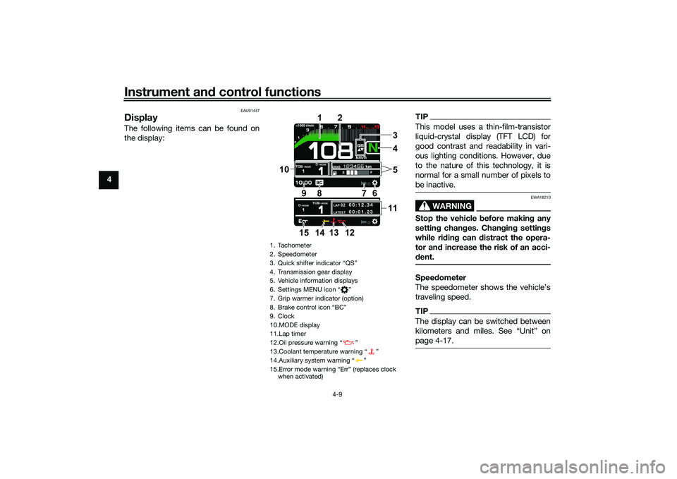
DisplayThe following items can be found on
the display:
TIPThis model uses a thin-film-transistor
liquid-crystal display (TFT LCD) for
good contrast and readability in vari-
ous lighting conditions. However, due
to the nature of this technology, it is
normal for a small number of pixels to
be inactive.
WARNING
EWA18210
Stop the vehicle b efore making any
settin g chan ges. Chan gin g settin gs
while ri din g can d istract the opera-
tor an d increase the risk of an acci-
d ent.Speed ometer
The speedometer shows the vehicle’s
traveling speed.TIPThe display can be switched between
page 4-17.
1. Tachometer
2. Speedometer
3.
4. Transmission gear display
5. Vehicle information displays
6. Settings MENU icon Ž
7. Grip warmer indicator (option)
8.
9. Clock
10.MODE display
11.Lap timer
12.Oil pressure warning Ž
13.Coolant temperature warning Ž
14.Auxiliary system warning Ž
when activated)
LAP 02LATEST
00:12.3 4
00:01.23
4
1
2
7
6
9
10
8
1135
14 13
12
15
UB7NE1E0.book Page 9 Friday, September 3, 2021 11:25 AM
Page 32 of 110
Instrument and control functions
4-11
4
If the vehicle coolant temperature
is above 124 °C (255 °F) the cool-
ant temperature display will read
“Hi”
To reset information display items1. Rotate the wheel switch to select
one of the two vehicle information
displays.
2. Press the wheel switch inward to highlight the information display.
3. Rotate the wheel switch to select the desired information display
item.
4. Press and hold the wheel switch inward until the highlighted dis-
play item is reset.
Transmission gear display
This shows which gear the transmis-
sion is in. This model has 6 gears and a
neutral position. The neutral position is
indicated by the neutral indicator
light “ ” and by the transmission gear
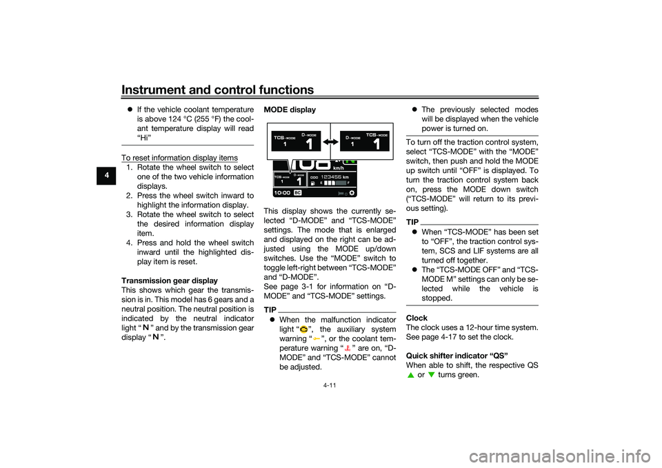
display “ ”. MODE
display
This display shows the currently se-
lected “D-MODE” and “TCS-MODE”
settings. The mode that is enlarged
and displayed on the right can be ad-
justed using the MODE up/down
switches. Use the “MODE” switch to
toggle left-right between “TCS-MODE”
and “D-MODE”.
See page 3-1 for information on “D-
MODE” and “TCS-MODE” settings.
TIP When the malfunction indicator
light “ ”, the auxiliary system
warning “ ”, or the coolant tem-
perature warning “ ” are on, “D-
MODE” and “TCS-MODE” cannot
be adjusted.
The previously selected modes
will be displayed when the vehicle
power is turned on.
To turn off the traction control system,
select “TCS-MODE” with the “MODE”
switch, then push and hold the MODE
up switch until “OFF” is displayed. To
turn the traction control system back
on, press the MODE down switch
(“TCS-MODE” will return to its previ-
ous setting).TIPWhen “TCS-MODE” has been set
to “OFF”, the traction control sys-
tem, SCS and LIF systems are all
turned off together.
The “TCS-MODE OFF” and “TCS-
M OD E M ” se t ti ng s c a n o n l y b e s e -
lected while the vehicle is
stopped.Clock
The clock uses a 12-hour time system.
See page 4-17 to set the clock.
Quick shifter in dicator “QS”
When able to shift, the respective QS or turns green.
UB7NE1E0.book Page 11 Friday, September 3, 2021 11:25 AM
Page 34 of 110
Instrument and control functions
4-13
4 To start the timer, press the pass
switch.
Each press of the pass switch will in-
crease the lap count by 1 and reset the
current lap timer.
To pause the lap timer, press the wheel
switch inward.
To unpause the timer, press the pass
switch and the timer will resume with-
out counting a new lap.
To exit the lap time mode, turn it off in
the settings MENU. (See page 4-14.)
TIP
The engine must be running to
start the lap timer.
The headlight will flash when the
pass switch is pressed.
Whenever the lap timer is paused,
it can be resumed using the pass
switch.Brake control icon “BC”
This icon is replaced by the auxiliary
system warning and coolant tempera-
ture warning indicators when they are
activated.
For more information on the BC sys-
tem see “BC” on page 3-4. Error mo
de warnin g “Err”
When an internal error occurs (e.g.,
communication with a system control-
ler has been cut off), the error mode
warning will appear as follows.
“Err” and “ ” indicator light indicates
an ECU error.
“Err” only indicates an ABS ECU error.
TIPDepending on the nature of the error,
the display may not function properly
and the traction control system set-
tings may be impossible to change.
Additionally, ABS may not function
properly. Use extra care when braking
and have a Yamaha dealer check the
vehicle immediately.Auxiliary system warnin g“”
This icon appears if a problem is de-
tected in a non-engine-related system.
Coolant temperature warnin g“”
This icon appears if the coolant tem-
perature reaches 116 °C (241 °F) or
higher. Stop the vehicle and turn off the
engine. Allow the engine to cool.
NOTICE
ECA10022
Do not continue to operate the en-
g ine if it is overheatin g.Oil pressure warnin g“”
This icon appears when the engine oil
pressure is low. When the vehicle is
first turned on, engine oil pressure has
yet to build, so this icon will come on
and stay on until the engine has been
started.TIPIf a malfunction is detected, the oil
pressure warning icon will flash repeat-
edly.NOTICE
ECA26410
Do not continue to operate the en-
g ine if the oil pressure is low.
UB7NE1E0.book Page 13 Friday, September 3, 2021 11:25 AM
Page 41 of 110
Instrument and control functions
4-20
4
EAU91461
Brake control system (BC)The brake control system regulates hy-
draulic brake pressure for the front and
rear wheels independently when the
brakes are applied and wheel lock is
detected. This system has two settings
which can be changed in the settings
MENU. (See page 4-15.)
BC1 is standard ABS, which adjusts
brake pressure based on vehicle
speed and wheel speed data. BC1 is
designed to engage and maximize
braking when the vehicle is upright.
BC2 uses additional data from the IMU
to regulate applied brake power when
cornering to suppress lateral wheel
slip.
Regarding ABS, operate the brakes as
you would conventional brakes. When
the brake control system engages, a
pulsating sensation may be felt at the
brake lever or brake pedal as the hy-
draulic unit rapidly applies and reduces
brake pressure. In this situation, con-
tinue to apply the brake lever and
brake pedal to allow the ABS to work—
do not “pump the brakes” as this will
reduce braking effectiveness.
WARNING
EWA16051
Always keep a sufficient d istance
from the vehicle ahead to match the
ri din g speed even with ABS.
The ABS performs best with
lon g b rakin g d istances.
On certain surfaces, such as
rou gh or g ravel roa ds, the b rak-
in g d istance may be lon ger with
the ABS than without.The ABS hydraulic unit is monitored by
the ABS ECU, which will revert the sys-
tem to conventional braking if a mal-
function occurs.
WARNING
EWA20891
The brake control system is not a
su bstitute for the use of proper ri d-
in g an d brakin g techniques. The
b rake control system cannot pre-
vent all loss of traction due to over-
b rakin g from excessive spee d, or
lateral wheel slip when brakin g on
slippery surfaces.
TIPThe ABS performs a self-diagnostic
test when the vehicle is started and
reaches a speed of 5 km/h (3 mi/h).
During this test, a clicking noise may
be audible from the hydraulic control
unit, and a vibration may be felt at the
brake lever or pedal, but this is normal.NOTICE
ECA20100
Be careful not to d amage the wheel
sensor or wheel sensor rotor; other-
wise, improper performance of the
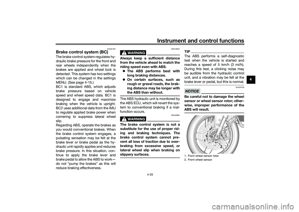
ABS will result.1. Front wheel sensor rotor
2. Front wheel sensor
1 1 1
2 2
UB7NE1E0.book Page 20 Friday, September 3, 2021 11:25 AM
Page 42 of 110
Instrument and control functions
4-21
4
EAU13077
Fuel tank capTo open the fuel tank cap
Open the fuel tank cap lock cover, in-
sert the key, and then turn it 1/4 turn
clockwise. The lock will be released
and the fuel tank cap can be opened.
To close the fuel tank cap
With the key still inserted, push down
the fuel tank cap. Turn the key 1/4 turn
counterclockwise, remove it, and then
close the lock cover.
TIPThe fuel tank cap cannot be closed un-
less the key is in the lock. In addition,
the key cannot be removed if the cap is
not properly closed and locked.
WARNING
EWA11092
Make sure that the fuel tank cap is
properly close d after fillin g fuel.
Leakin g fuel is a fire hazar d.
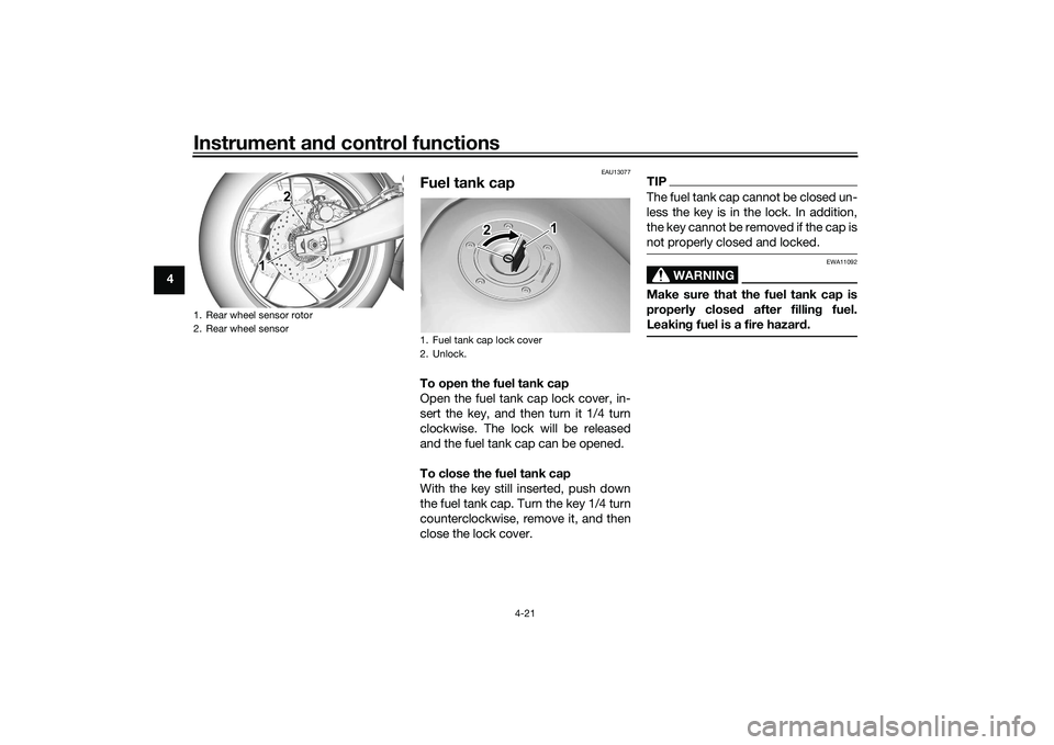
1. Rear wheel sensor rotor
2. Rear wheel sensor
1 1 1 2 2
1. Fuel tank cap lock cover
2. UnlockK
1
2
UB7NE1E0.book Page 21 Friday, September 3, 2021 11:25 AM
Page 43 of 110
Instrument and control functions
4-22
4
EAU13222
FuelMake sure there is sufficient gasoline in
the tank.
WARNING
EWA10882
Gasoline an d gasoline vapors are
extremely flammab le. To avoid fires
an d explosions an d to re duce the
risk of injury when refueling , follow
these instructions.1. Before refueling, turn off the en- gine and be sure that no one is sit-
ting on the vehicle. Never refuel
while smoking, or while in the vi-
cinity of sparks, open flames, or
other sources of ignition such as
the pilot lights of water heaters
and clothes dryers.
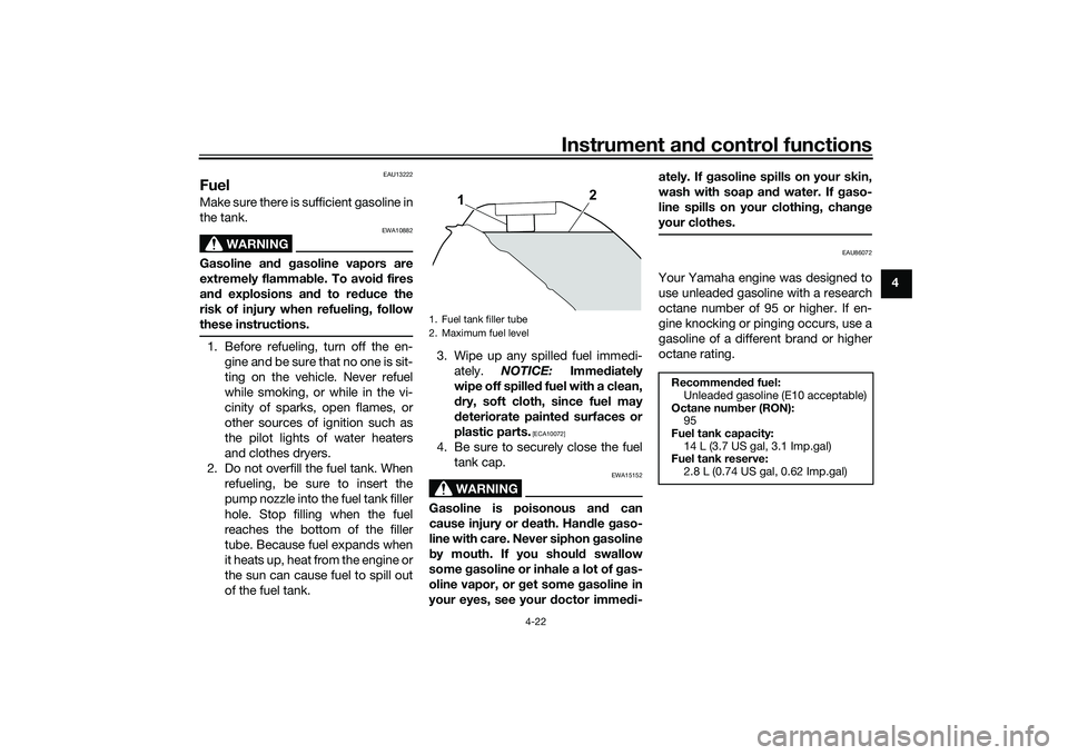
2. Do not overfill the fuel tank. When refueling, be sure to insert the
pump nozzle into the fuel tank filler
hole. Stop filling when the fuel
reaches the bottom of the filler
tube. Because fuel expands when
it heats up, heat from the engine or
the sun can cause fuel to spill out
of the fuel tank. 3. Wipe up any spilled fuel immedi-
ately. NOTICE: Immediately
wipe off spille d fuel with a clean,
d ry, soft cloth, since fuel may
d eteriorate painte d surfaces or
plastic parts.
[ECA10072]
4. Be sure to securely close the fuel tank cap.
WARNING
EWA15152
Gasoline is poisonous an d can
cause injury or d eath. Handle gaso-
line with care. Never siphon gasoline
b y mouth. If you shoul d swallow
some gasoline or inhale a lot of gas-
oline vapor, or g et some gasoline in
your eyes, see your doctor imme di- ately. If g
asoline spills on your skin,
wash with soap an d water. If gaso-
line spills on your clothin g, chan ge
your clothes.
EAU86072
Your Yamaha engine was designed to
use unleaded gasoline with a research
octane number of 95 or higher. If en-
gine knocking or pinging occurs, use a
gasoline of a different brand or higher
octane rating.
1. Fuel tank filler tube
2. Maximum fuel level
1
2
Recommen ded fuel:
Unleaded gasoline (E10 acceptable)
Octane num ber (RON):
95
Fuel tank capacity: 14 L (3.7 US gal, 3.1 Imp.gal)
Fuel tank reserve:
2.8 L (0.74 US gal, 0.62 Imp.gal)
UB7NE1E0.book Page 22 Friday, September 3, 2021 11:25 AM
Page 45 of 110
Instrument and control functions
4-24
4
TIPSee page 7-10 for canister information.
EAU13435
Catalytic converterThe exhaust system contains catalytic
converter(s) to reduce harmful exhaust
emissions.
WARNING
EWA10863
The exhaust system is hot after op-
eration. To prevent a fire hazar d or
b urns:
Do not park the vehicle near
possi ble fire hazar ds such as
g rass or other materials that
easily burn.
Park the vehicle in a place
where pe destrians or child ren
are not likely to touch the hot
exhaust system.
Make sure that the exhaust sys-
tem has cooled down before
d oin g any maintenance work.
Do not allow the en gine to id le
more than a few minutes. Lon g
i d lin g can cause a buil d-up of
heat.
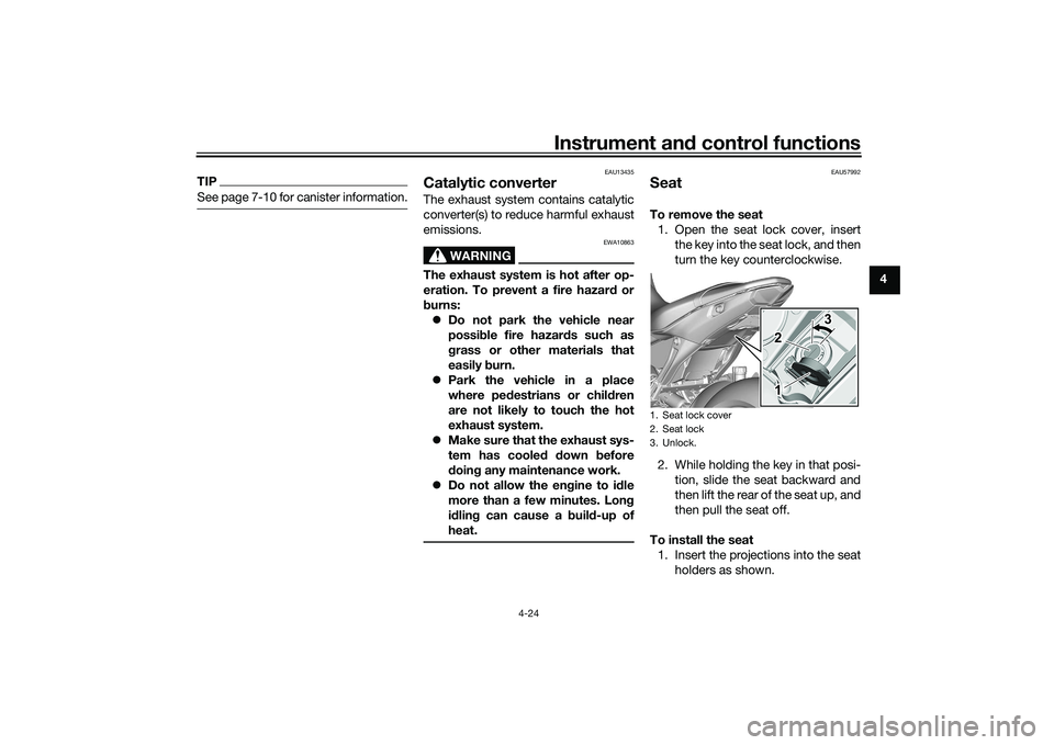
EAU57992
SeatTo remove the seat 1. Open the seat lock cover, insert the key into the seat lock, and then
turn the key counterclockwise.
2. While holding the key in that posi- tion, slide the seat backward and
then lift the rear of the seat up, and
then pull the seat off.
To install the seat 1. Insert the projections into the seat holders as shown.1. Seat lock cover
2. Seat lock
3. Unlock.
3 3
1 2 3
1
2
UB7NE1E0.book Page 24 Friday, September 3, 2021 11:25 AM
Page 47 of 110

Instrument and control functions
4-26
4
EAU76345
A djustin g the front fork
WARNING
EWA14671
Always a djust the sprin g preloa d on
b oth fork leg s equally, otherwise
poor han dlin g an d loss of sta bility
may result.Each front fork leg is equipped with a
spring preload adjusting bolt, the right
front fork leg is equipped with a re-
bound damping force adjusting screw
and the left front fork leg with a com-
pression damping force adjusting
screw.NOTICE
ECA10102
To avoi d d amag ing the mechanism,
d o not attempt to turn b eyond the
maximum or minimum settin gs.Sprin g preloa d
Turn the adjusting bolt in direction (a)
to increase the spring preload.
Turn the adjusting bolt in direction (b)
to decrease the spring preload. The spring preload setting is deter-
mined by measuring distance A,
shown in the illustration. The shorter
distance A is, the higher the spring pre-
load; the longer distance A is, the lower
the spring preload.
Re
boun d d ampin g force
The rebound damping force is adjust-
ed on the right fork leg only.
Turn the adjusting screw in direction (a)
to increase the rebound damping
force.
Turn the adjusting screw in direction (b)
to decrease the rebound damping
force.
To set the rebound damping force, turn
the adjuster in direction (a) until it
stops, and then count the clicks in di-
rection (b).
TIPBe sure to perform this adjustment on
the right fork leg.
1. Spring preload adjusting bolt
1. Distance A
(b)
1 1 1
(a)
(b)(a)
1
Sprin
g preloa d settin g:
Minimum (soft):
Distance A = 19.0 mm (0.75 in)
Standard:
Distance A = 15.0 mm (0.59 in)
Maximum (hard): Distance A = 4.0 mm (0.16 in)
UB7NE1E0.book Page 26 Friday, September 3, 2021 11:25 AM