warning YAMAHA MT-09 2022 Owners Manual
[x] Cancel search | Manufacturer: YAMAHA, Model Year: 2022, Model line: MT-09, Model: YAMAHA MT-09 2022Pages: 110, PDF Size: 3.8 MB
Page 5 of 110
Introduction
EAU10103
Welcome to the Yamaha world of motorcycling!
As the owner of the MTN890, you are benefiting from Yamaha’s vast experience and newest technology regarding the de-
sign and manufacture of high-quality products, which have earned Yamaha a reputation for dependability.
Please take the time to read this manual thoroughly, so as to enjoy all advantages of your MTN890. The Owner’s Manual
does not only instruct you in how to operate, inspect and maintain your motorcycle, but also in how to safeguard yourself
and others from trouble and injury.
In addition, the many tips given in this manual will help keep your motorcycle in the best possible condition. If you have any
further questions, do not hesitate to contact your Yamaha dealer.
The Yamaha team wishes you many safe and pleasant rides. So, remember to put safety first!
Yamaha continually seeks advancements in product design and quality. Therefore, while this manual contains the most cur- rent product information available at the time of printing, there may be minor discrepancies between your motorcycle and
this manual. If there is any question concerning this manual, please consult a Yamaha dealer.
WARNING
EWA10032
Please rea d this manual carefully an d completely before operatin g this motorcycle.
UB7NE1E0.book Page 1 Friday, September 3, 2021 11:25 AM
Page 6 of 110
Important manual information
EAU10134
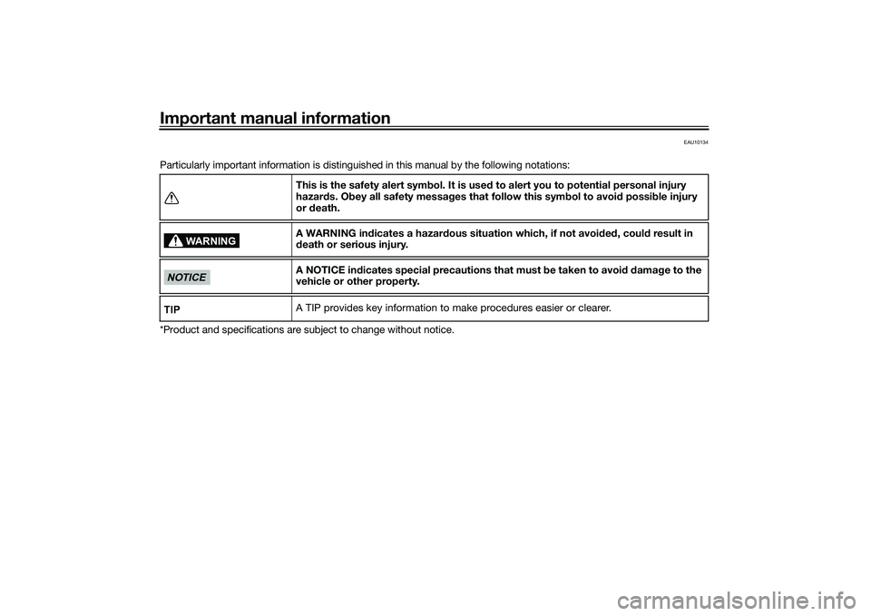
Particularly important information is distinguished in this manual by the following notations:
*Product and specifications are subject to change without notice.This is the safety alert sym
bol. It is use d to alert you to potential personal injury
hazar ds. Ob ey all safety messa ges that follow this sym bol to avoi d possi ble injury
or death.
A WARNING in dicates a hazar dous situation which, if not avoid ed , coul d result in
d eath or serious injury.
A NOTICE in dicates special precautions that must b e taken to avoid d ama ge to the
vehicle or other property.
A TIP provides key information to make procedures easier or clearer.
WARNING
NOTICETIP
UB7NE1E0.book Page 1 Friday, September 3, 2021 11:25 AM
Page 8 of 110
Table of contentsSafety information ............................ 1-1
Description ....................................... 2-1
Left view ......................................... 2-1
Right view ....................................... 2-2
Controls and instruments ............... 2-3
Special features .............................. 3-1
“D-MODE” ...................................... 3-1
“TCS-MODE”.................................. 3-1
Quick shifter ................................... 3-3
BC................................................... 3-4
Instrument an d control functions ... 4-1
Immobilizer system......................... 4-1
Main switch/steering lock............... 4-2
Handlebar switches ........................ 4-3
Indicator lights and warning lights............................................ 4-5
Display ............................................ 4-9
Settings MENU ............................. 4-14
Clutch lever .................................. 4-18
Shift pedal .................................... 4-18
Brake lever.................................... 4-19
Brake pedal .................................. 4-19
Brake control system (BC)............ 4-20
Fuel tank cap ................................ 4-21
Fuel ............................................... 4-22
Fuel tank overflow hose ............... 4-23
Catalytic converter ....................... 4-24
Seat .............................................. 4-24 Rider footrest position .................. 4-25
Handlebar position ....................... 4-25
Adjusting the front fork ................. 4-26
Adjusting the shock absorber
assembly.................................... 4-28
Luggage strap holders .................. 4-30
Auxiliary DC connectors ............... 4-30
Sidestand ...................................... 4-30
Ignition circuit cut-off system ....... 4-31
For your safety – pre-operation
checks ............................................... 5-1
Operation an d important ri din g
points ................................................. 6-1
Engine break-in ............................... 6-1
Starting the engine .......................... 6-2
Shifting ............................................ 6-3
Tips for reducing fuel consumption ................................ 6-4
Parking ............................................ 6-5
Perio dic maintenance an d
a d justment ........................................ 7-1
Tool kit ............................................ 7-2
Periodic maintenance charts .......... 7-3
Periodic maintenance chart for the emission control system .............. 7-3
General maintenance and
lubrication chart ........................... 7-5
Checking the spark plugs ............... 7-9 Canister ........................................ 7-10
Engine oil ...................................... 7-10
Why Yamalube.............................. 7-12
Coolant ......................................... 7-13
Air filter element ............................ 7-14
Checking the engine idling
speed ........................................ 7-14
Valve clearance............................. 7-15
Tires .............................................. 7-15
Cast wheels .................................. 7-17
Adjusting the clutch lever free
play ............................................ 7-18
Checking the brake lever free play ............................................ 7-18
Brake light switches ..................... 7-19
Checking the front and rear brake pads ................................ 7-19
Checking the brake fluid level ...... 7-20
Changing the brake fluid .............. 7-21
Drive chain slack........................... 7-22
Cleaning and lubricating the drive chain ................................. 7-24
Checking and lubricating the
cables ........................................ 7-24
Checking and lubricating the throttle grip ................................ 7-25
Checking and lubricating the brake and shift pedals............... 7-25
Checking and lubricating the
brake and clutch levers ............. 7-26UB7NE1E0.book Page 1 Friday, September 3, 2021 11:25 AM
Page 10 of 110
1-1
1
Safety information
EAU1028C
Be a Responsible Owner
As the vehicle’s owner, you are re-
sponsible for the safe and proper oper-
ation of your motorcycle.
Motorcycles are single-track vehicles.
Their safe use and operation are de-
pendent upon the use of proper riding
techniques as well as the expertise of
the operator. Every operator should
know the following requirements be-
fore riding this motorcycle.
He or she should: Obtain thorough instructions from
a competent source on all aspects
of motorcycle operation.
Observe the warnings and mainte-
nance requirements in this Own-
er’s Manual.
Obtain qualified training in safe
and proper riding techniques.
Obtain professional technical ser-
vice as indicated in this Owner’s
Manual and/or when made neces-
sary by mechanical conditions.
Never operate a motorcycle with-
out proper training or instruction.
Take a training course. Beginners
should receive training from a cer-
tified instructor. Contact an autho-
rized motorcycle dealer to find out
about the training courses nearest
you.
Safe Ri din g
Perform the pre-operation checks
each time you use the vehicle to make
sure it is in safe operating condition.
Failure to inspect or maintain the vehi-
cle properly increases the possibility of
an accident or equipment damage.
See page 5-1 for a list of pre-operation
checks. This motorcycle is designed to
carry the operator and a passen-
ger.
The failure of motorists to detect
and recognize motorcycles in traf-
fic is the predominating cause of
automobile/motorcycle accidents.
Many accidents have been
caused by an automobile driver
who did not see the motorcycle.
Making yourself conspicuous ap- pears to be very effective in reduc-
ing the chance of this type of
accident.
Therefore:
• Wear a brightly colored jacket.
• Use extra caution when you are approaching and passing
through intersections, since in-
tersections are the most likely
places for motorcycle accidents
to occur.
• Ride where other motorists can see you. Avoid riding in another
motorist’s blind spot.
• Never maintain a motorcycle without proper knowledge.
Contact an authorized motorcy-
cle dealer to inform you on ba-
sic motorcycle maintenance.
Certain maintenance can only
be carried out by certified staff.UB7NE1E0.book Page 1 Friday, September 3, 2021 11:25 AM
Page 18 of 110
Special features
3-1
3
EAU91323
“D-MODE”“D-MODE” is an electronically con-
trolled engine performance system.
WARNING
EWA18440
Do not change the d rive mo de while
the vehicle is movin g.The “D-MODE” system consists of 4
different control maps which regulate
engine response and output, thus pro-
viding you with a selection of modes to
fit your preferences and the riding envi-
ronment.
D-MODE 1 - Sporty engine response
D-MODE 2 - Moderate engine re-
sponse
D-MODE 3 - Mild engine response
D-MODE 4 - Mild engine response and
limits engine outputTIP The current “D-MODE” setting is
shown in the MODE display. (See
page 4-11.)
The current “D-MODE” setting is
saved when the vehicle is turned
off.
The “D-MODE” is controlled by
the MODE switches, see page 4-4
for more information.
EAU91434
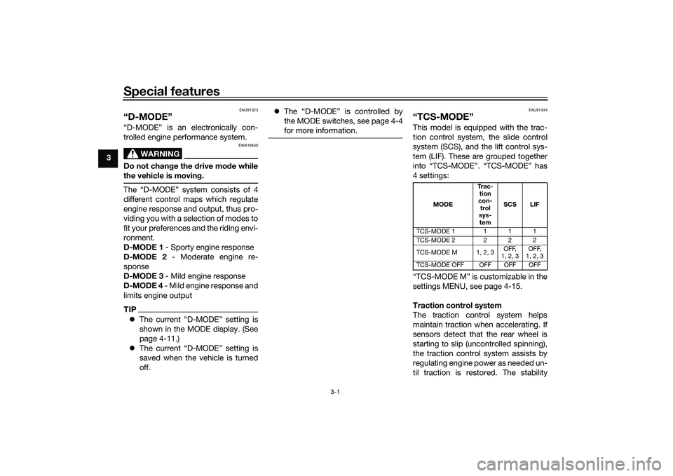
“TCS-MODE”This model is equipped with the trac-
tion control system, the slide control
system (SCS), and the lift control sys-
tem (LIF). These are grouped together
into “TCS-MODE”. “TCS-MODE” has
4 settings:
“TCS-MODE M” is customizable in the
settings MENU, see page 4-15.
Traction control system
The traction control system helps
maintain traction when accelerating. If
sensors detect that the rear wheel is
starting to slip (uncontrolled spinning),
the traction control system assists by
regulating engine power as needed un-
til traction is restored. The stability
MODE Tr a c -
tion
con- trol
sys- tem SCS LIF
TCS-MODE 1 111
TCS-MODE 2 222
TCS-MODE M 1, 2, 3 OFF,
1, 2, 3 OFF,
1, 2, 3
TCS-MODE OFF OFF OFF OFF
UB7NE1E0.book Page 1 Friday, September 3, 2021 11:25 AM
Page 19 of 110
Special features
3-2
3
control indicator light “ ” flashes to
let the rider know that traction control
has engaged.
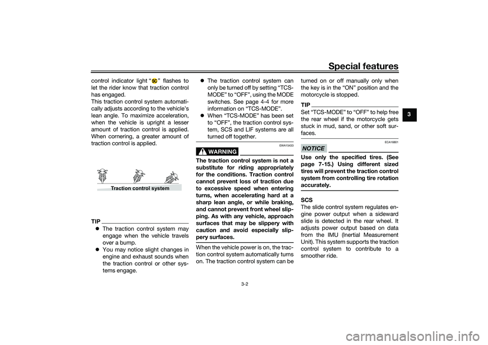
This traction control system automati-
cally adjusts according to the vehicle’s
lean angle. To maximize acceleration,
when the vehicle is upright a lesser
amount of traction control is applied.
When cornering, a greater amount of
traction control is applied.
TIP
The traction control system may
engage when the vehicle travels
over a bump.
You may notice slight changes in
engine and exhaust sounds when
the traction control or other sys-
tems engage.
The traction control system can
only be turned off by setting “TCS-
MODE” to “OFF”, using the MODE
switches. See page 4-4 for more
information on “TCS-MODE”.
When “TCS-MODE” has been set
to “OFF”, the traction control sys-
tem, SCS and LIF systems are all
turned off together.
WARNING
EWA15433
The traction control system is not a
substitute for ri din g appropriately
for the con ditions. Traction control
cannot prevent loss of traction d ue
to excessive spee d when enterin g
turns, when acceleratin g har d at a
sharp lean an gle, or while brakin g,
an d cannot prevent front wheel slip-
pin g. As with any vehicle, approach
surfaces that may be slippery with
caution an d avoi d especially slip-
pery surfaces.When the vehicle power is on, the trac-
tion control system automatically turns
on. The traction control system can be turned on or off manually only when
the key is in the “ON” position and the
motorcycle is stopped.
TIP
the rear wheel if the motorcycle gets
stuck in mud, sand, or other soft sur-
faces.NOTICE
ECA16801
Use only the specifie
d tires. (See
pa ge 7-15.) Usin g different size d
tires will prevent the traction control
system from controllin g tire rotation
accurately.SCS
The slide control system regulates en-
gine power output when a sideward
slide is detected in the rear wheel. It
adjusts power output based on data
from the IMU (Inertial Measurement
Unit). This system supports the traction
control system to contribute to a
smoother ride.
Traction control system
UB7NE1E0.book Page 2 Friday, September 3, 2021 11:25 AM
Page 21 of 110
Special features
3-4
3
EAU91350
BCThe brake control system regulates hy-
draulic brake pressure for the front and
rear wheels when the brakes are ap-
plied and wheel lock is detected. This
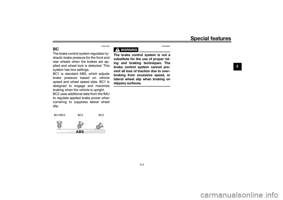
system has two settings.
BC1 is standard ABS, which adjusts
brake pressure based on vehicle
speed and wheel speed data. BC1 is
designed to engage and maximize
braking when the vehicle is upright.
BC2 uses additional data from the IMU
to regulate applied brake power when
cornering to suppress lateral wheel
slip.
WARNING
EWA20891
The brake control system is not a
su bstitute for the use of proper ri d-
in g an d brakin g techniques. The
b rake control system cannot pre-
vent all loss of traction due to over-
b rakin g from excessive spee d, or
lateral wheel slip when brakin g on
slippery surfaces.
ABS
BC1/BC2 BC2 BC2
UB7NE1E0.book Page 4 Friday, September 3, 2021 11:25 AM
Page 23 of 110
Instrument and control functions
4-2
4
EAU10474
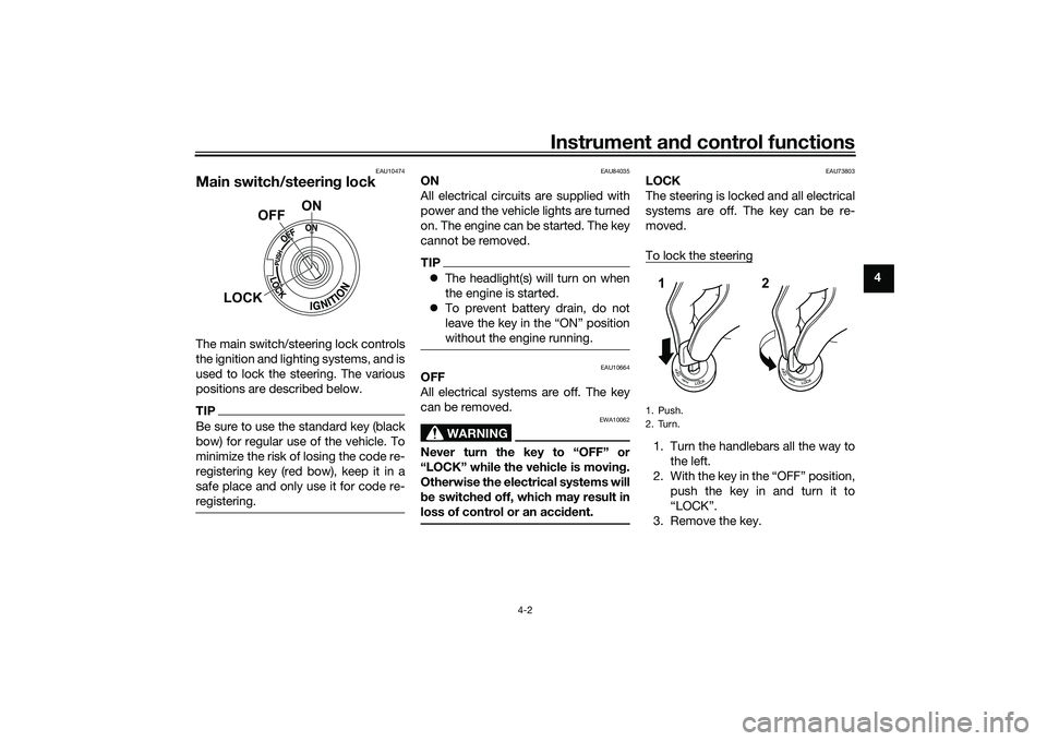
Main switch/steerin g lockThe main switch/steering lock controls
the ignition and lighting systems, and is
used to lock the steering. The various
positions are described below.TIPBe sure to use the standard key (black
bow) for regular use of the vehicle. To
minimize the risk of losing the code re-
registering key (red bow), keep it in a
safe place and only use it for code re-
registering.
EAU84035
ON
All electrical circuits are supplied with
power and the vehicle lights are turned
on. The engine can be started. The key
cannot be removed.TIP The headlight(s) will turn on when
the engine is started.
To prevent battery drain, do not
leave the key in the “ON” position
without the engine running.
EAU10664
OFF
All electrical systems are off. The key
can be removed.
WARNING
EWA10062
Never turn the key to “OFF” or
“LOCK” while the vehicle is movin g.
Otherwise the electrical systems will
b e switched off, which may result in
loss of control or an acci dent.
EAU73803
LOCK
The steering is locked and all electrical
systems are off. The key can be re-
moved.
To lock the steering1. Turn the handlebars all the way to
the left.
2. With the key in the “OFF” position, push the key in and turn it to
“LOCK”.
3. Remove the key.
ON
OFF
LOCK
1. PushK
2. TurnK12
UB7NE1E0.book Page 2 Friday, September 3, 2021 11:25 AM
Page 26 of 110
Instrument and control functions
4-5
4
The “TCS-MODE” can only be
turned off from the main display.
Select “TCS-MODE” with the
“MODE” switch, then push and
hold the MODE up switch until
“OFF” is displayed.
To turn the traction control system
back on, use the MODE down
switch.
When “TCS-MODE” has been set
to “OFF”, the traction control sys-
tem, SCS and LIF systems are all
turned off together.
See page 4-11 for more informa-
tion on the MODE display.
See page 3-1 for more information
on “TCS-MODE”.
See page 3-1 for more information
on “D-MODE”.
EAU91373
Wheel switch “ ”
When the wheel switch is operated, a
cursor will appear around the previous-
ly selected item on the display.
The wheel switch controls:
Vehicle information displays
Settings MENU
Grip warmer function (Option) Operate the wheel switch as follows:
Rotate up
- rotate the wheel upward to
scroll up or increase a setting value.
Rotate down - rotate the wheel down-
ward to scroll down or decrease a set-
ting value.
Push inwar d - press the wheel switch
in towards the handlebar to select
items indicated by the cursor and con-
firm settings changes. Press and hold
the switch inward to reset selected
items.
TIP If the wheel switch is not operated
for a certain period of time, the
cursor will disappear.
For items that can be reset, leave
the cursor over the item, press
and hold the switch to reset.
See page 4-9 for more information
on the main screen and its func-
tions.
See page 4-14 for more informa-
tion on the MENU screen and how
to make settings changes.
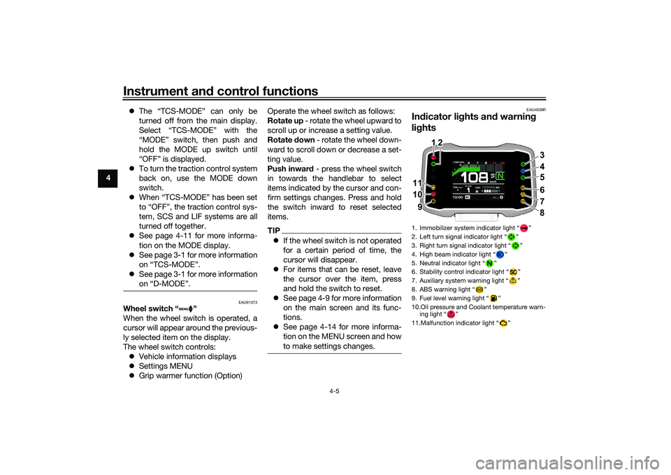
EAU4939R
Indicator li ghts and warning
li g hts1. Immobilizer system indicator light “ ”
2. Left turn signal indicator light “ ”
3. Right turn signal indicator light “ ”
4. High beam indicator light “ ”
5. Neutral indicator light “ ”
6. Stability control indicator light “ ”
7. Auxiliary system warning light “ ”
8. ABS warning light “ ”
9. Fuel level warning light “ ”
10.Oil pressure and Coolant temperature warn-
ing light “ ”
11.Malfunction indicator light “ ”
ABS
3
4
56
7
8
11 11
10 10
9
11 1 12
2 2
10 9 9
UB7NE1E0.book Page 5 Friday, September 3, 2021 11:25 AM
Page 27 of 110
Instrument and control functions
4-6
4
EAU88280
Turn si gnal in dicator li ghts “ ”
an d“”
Each indicator light will flash when its
corresponding turn signal lights are
flashing.
EAU88300
Neutral in dicator li ght “ ”
This indicator light comes on when the
transmission is in the neutral position.
EAU88310
Hi gh beam in dicator li ght “ ”
This indicator light comes on when the
high beam of the headlight is switched
on.
EAU88320
Fuel level warning light “ ”
This warning light comes on when the
fuel level drops below approximately
2.8 L (0.74 US gal, 0.62 Imp.gal). When
this occurs, refuel as soon as possible.
The electrical circuit of the warning
light can be checked by turning the ve-
hicle on. The warning light should
come on for a few seconds, and then
go off.
TIPIf the warning light does not come on at
all, remains on after refueling, or if the
warning light flashes repeatedly, have
a Yamaha dealer check the vehicle.
EAU88331
Malfunction in dicator li ght
(MIL) “ ”
This light comes on or flashes if a prob-
lem is detected in the engine or other
vehicle control system. If this occurs,
have a Yamaha dealer check the on-
board diagnostic system. The electri-
cal circuit of the warning light can be
checked by turning the vehicle power
on. The light should come on for a few
seconds, and then go off. If the light
does not come on initially when the ve-
hicle power is turned on, or if the light
remains on, have a Yamaha dealer
check the vehicle.NOTICE
ECA26820
If the MIL starts flashin g, re duce en-
g ine spee d to prevent exhaust sys-
tem damag e.
TIPThe engine is sensitively monitored by
the on-board diagnostic system to de-
tect deterioration or malfunction of the
emission control system. Therefore the
MIL may come on or flash due to vehi-
cle modifications, lack of maintenance,
or excessive/improper use of the mo-
torcycle. To prevent this, observe
these precautions.
Do not attempt to modify the soft-
ware of the engine control unit.
Do not add any electrical acces-
sories that interfere with engine
control.
Do not use aftermarket accesso-
ries or parts such as suspension,
spark plugs, injectors, exhaust
system, etc.
Do not change the drivetrain
specifications (chain, sprockets,
wheels, tires, etc.).
Do not remove or alter the O2 sen-
sor, air induction system, or ex-
haust parts (catalysts or EXUP,
etc.).
Maintain the drive chain properly.
Maintain correct tire pressure.
UB7NE1E0.book Page 6 Friday, September 3, 2021 11:25 AM