fuse YAMAHA MT-09 2022 Owners Manual
[x] Cancel search | Manufacturer: YAMAHA, Model Year: 2022, Model line: MT-09, Model: YAMAHA MT-09 2022Pages: 110, PDF Size: 3.8 MB
Page 9 of 110
Table of contents
Checking and lubricating the
sidestand ...................................7-26
Lubricating the swingarm pivots ...7-27
Checking the front fork..................7-27
Checking the steering ...................7-28
Checking the wheel bearings ........7-28
Battery ...........................................7-28
Replacing the fuses .......................7-30
Vehicle lights .................................7-32
License plate light .........................7-32
Supporting the motorcycle............7-32
Troubleshooting ............................7-33
Troubleshooting chart ...................7-34
Motorcycle care an d stora ge ..........8-1
Matte color caution .........................8-1
Care .................................................8-1
Storage ............................................8-3
Specifications ....................................9-1
Consumer information ...................10-1
Identification numbers ...................10-1
Diagnostic connector ....................10-2
Vehicle data recording ..................10-2
In dex ................................................11-1
UB7NE1E0.book Page 2 Friday, September 3, 2021 11:25 AM
Page 16 of 110
Description
2-2
2
EAU10421
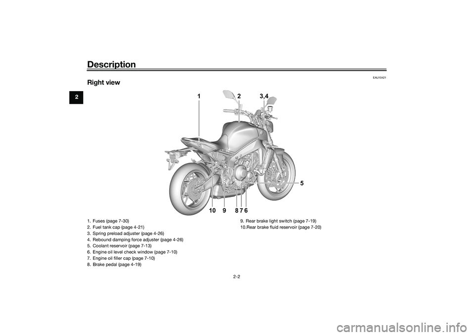
Right view
1 2 3,4
5
9
10 6
78
1. Fuses (page 7-30)
2. Fuel tank cap (page 4-21)
3. Spring preload adjuster (page 4-26)
4. Rebound damping force adjuster (page 4-26)
5. Coolant reservoir (page 7-13)
6. Engine oil level check window (page 7-10)
7. Engine oil filler cap (page 7-10)
8. Brake pedal (page 4-19) 9. Rear brake light switch (page 7-19)
10.Rear brake fluid reservoir (page 7-20)UB7NE1E0.book Page 2 Friday, September 3, 2021 11:25 AM
Page 91 of 110
Periodic maintenance an d a djustment
7-30
7
EAU91572
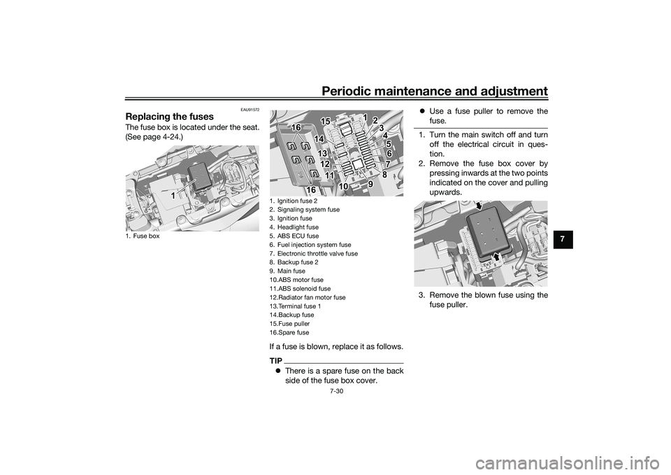
Replacin g the fusesThe fuse box is located under the seat.
(See page 4-24.)
If a fuse is blown, replace it as follows.
TIPThere is a spare fuse on the back
side of the fuse box cover.
Use a fuse puller to remove the
fuse.
1. Turn the main switch off and turn
off the electrical circuit in ques-
tion.
2. Remove the fuse box cover by pressing inwards at the two points
indicated on the cover and pulling
upwards.
3. Remove the blown fuse using the fuse puller.
1. Fuse box
1 1 1
1. Ignition fuse O
2. Signaling system fuse
3. Ignition fuse
4. Headlight fuse
5. ABS ECU fuse
6. Fuel injection system fuse
7. Electronic throttle valve fuse
8. Backup fuse O
9. Main fuse
10.ABS motor fuse
11.ABS solenoid fuse
12.Radiator fan motor fuse
13.Terminal fuse 1
14.Backup fuse
15.Fuse puller
16.Spare fuse
1 12
3
4
5
6
7
8
1
2
3
4
5
6
7
8
9
10 10
11 11
12 12
13 13
14 14
16 16
16 16 9
10
11
12
13
14
16
1615 15 15
UB7NE1E0.book Page 30 Friday, September 3, 2021 11:25 AM
Page 92 of 110
Periodic maintenance an d a djustment
7-31
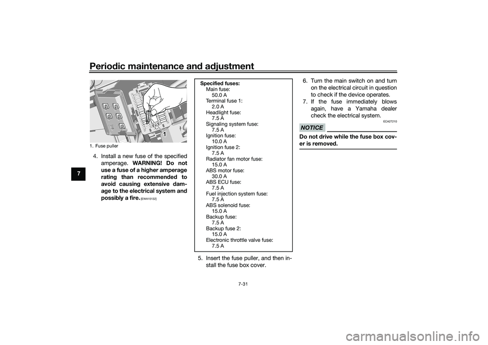
7 4. Install a new fuse of the specified
amperage. WARNING! Do not
use a fuse of a hi gher ampera ge
ratin g than recommen ded to
avoi d causin g extensive d am-
a g e to the electrical system an d
possi bly a fire.
[EWA15132]
5. Insert the fuse puller, and then in-
stall the fuse box cover. 6. Turn the main switch on and turn
on the electrical circuit in question
to check if the device operates.
7. If the fuse immediately blows again, have a Yamaha dealer
check the electrical system.
NOTICE
ECA27210
Do not drive while the fuse box cov-
er is removed .
1. Fuse puller
1 1 1
Specified fuses:
Main fuse:
50.0 A
Te r m i n a l f u s e 1 :
2.0 A
Headlight fuse: 7.5 A
Signaling system fuse: 7.5 A
Ignition fuse:
10.0 A
Ignition fuse 2: 7.5 A
Radiator fan motor fuse: 15.0 A
ABS motor fuse:
30.0 A
ABS ECU fuse: 7.5 A
Fuel injection system fuse: 7.5 A
ABS solenoid fuse:
15.0 A
Backup fuse: 7.5 A
Backup fuse 2: 15.0 A
Electronic throttle valve fuse:
7.5 A
UB7NE1E0.book Page 31 Friday, September 3, 2021 11:25 AM
Page 93 of 110
Periodic maintenance an d a djustment
7-32
7
EAU80380
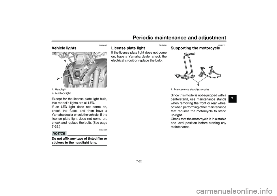
Vehicle li ghtsExcept for the license plate light bulb,
this model’s lights are all LED.
If an LED light does not come on,
check the fuses and then have a
Yamaha dealer check the vehicle. If the license plate light does not come on,
check and replace the bulb. (See page
7-32.)NOTICE
ECA16581
Do not affix any type of tinte d film or
stickers to the head lig ht lens.
EAU24331
License plate li ghtIf the license plate light does not come
on, have a Yamaha dealer check the
electrical circuit or replace the bulb.
EAU67131
Supportin g the motorcycleSince this model is not equipped with a
centerstand, use maintenance stands
when removing the front or rear wheel
or when performing other maintenance
that requires the motorcycle to stand
up right.
Check that the motorcycle is in a stable
and level position before starting any
maintenance.
1. Headlight
2. Auxiliary light
2 2 2
2 1
1. Maintenance stand (exampleF
1
UB7NE1E0.book Page 32 Friday, September 3, 2021 11:25 AM
Page 106 of 110
11-1
11
IndexAABS warning light ................................... 4-7
Air filter element .................................... 7-14
Auxiliary DC connectors ....................... 4-30
Auxiliary system warning light ................ 4-8BBattery .................................................. 7-28
BC ........................................................... 3-4
Brake and clutch levers, checking
and lubricating .................................... 7-26
Brake and shift pedals, checking and lubricating ........................................... 7-25
Brake control system (BC) .................... 4-20
Brake fluid, changing ............................ 7-21
Brake fluid level, checking .................... 7-20
Brake lever ............................................ 4-19
Brake lever free play, checking............. 7-18
Brake light switches.............................. 7-19
Brake pedal........................................... 4-19CCables, checking and lubricating ......... 7-24
Canister................................................. 7-10
Care ........................................................ 8-1
Catalytic converter ................................ 4-24
Clutch lever ........................................... 4-18
Clutch lever free play, adjusting ........... 7-18
Coolant ................................................. 7-13DData recording, vehicle ......................... 10-2
Diagnostic connector............................ 10-2
Dimmer switch ........................................ 4-4
Display .................................................... 4-9
Display, menu screen ........................... 4-14
D-MODE ................................................. 3-1 Drive chain, cleaning and lubricating ... 7-24
Drive chain slack .................................. 7-22
EEngine break-in ...................................... 6-1
Engine idling speed, checking ............. 7-14
Engine oil .............................................. 7-10
Engine overheating ............................... 7-35
Engine serial number ............................ 10-1FFront and rear brake pads, checking ... 7-19
Front fork, adjusting ............................. 4-26
Front fork, checking ............................. 7-27
Fuel ....................................................... 4-22
Fuel consumption, tips for reducing ...... 6-4
Fuel level warning light ........................... 4-6
Fuel tank cap ........................................ 4-21
Fuel tank overflow hose ....................... 4-23
Fuses, replacing ................................... 7-30HHandlebar position, adjusting .............. 4-25
Handlebar switches ................................ 4-3
Hazard switch......................................... 4-4
High beam indicator light ....................... 4-6
Horn switch ............................................ 4-4IIdentification numbers .......................... 10-1
Ignition circuit cut-off system ............... 4-31
Immobilizer system ................................ 4-1
Immobilizer system indicator light .......... 4-7
Indicator lights and warning lights ......... 4-5LLicense plate light ................................ 7-32
Luggage strap holders ......................... 4-30
MMain switch/steering lock .......................4-2
Maintenance and lubrication, periodic....7-5
Maintenance, emission control
system ..................................................7-3
Malfunction indicator light (MIL)..............4-6
Matte color, caution ................................8-1
Model label ...........................................10-1NNeutral indicator light ..............................4-6OOil pressure and Coolant temperature warning light .........................................4-8PParking ....................................................6-5
Part locations ..........................................2-1
Pass switch .............................................4-4QQuick shifter ............................................3-3RRider footrest position, adjusting ..........4-25SSafety information ...................................1-1
Seat .......................................................4-24
Shifting ....................................................6-3
Shift pedal .............................................4-18
Shock absorber assembly, adjusting ....4-28
Sidestand ..............................................4-30
Sidestand, checking and lubricating.....7-26
Spark plugs, checking ............................7-9
Special features ......................................3-1
Specifications .........................................9-1
Stability control indicator light ................4-7
Starting the engine ..................................6-2
UB7NE1E0.book Page 1 Friday, September 3, 2021 11:25 AM