key YAMAHA MT-10 2020 User Guide
[x] Cancel search | Manufacturer: YAMAHA, Model Year: 2020, Model line: MT-10, Model: YAMAHA MT-10 2020Pages: 108, PDF Size: 9.22 MB
Page 33 of 108
Instrument and control functions
4-12
1
2
345
6
7
8
9
10
11
12
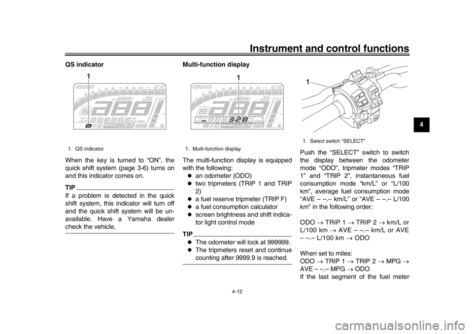
QS indicator
When the key is turned to “ON”, the
quick shift system (page 3-6) turns on
and this indicator comes on.
TIPIf a problem is detected in the quick
shift system, this indicator will turn off
and the quick shift system will be un-
available. Have a Yamaha dealercheck the vehicle.
Multi-function display
The multi-function display is equipped
with the following:
an odometer (ODO)
two tripmeters (TRIP 1 and TRIP
2)
a fuel reserve tripmeter (TRIP F)
a fuel consumption calculator
screen brightness and shift indica-
tor light control mode
TIP
The odometer will lock at 999999.
The tripmeters reset and continuecounting after 9999.9 is reached.
Push the “SELECT” switch to switch
the display between the odometer
mode “ODO”, tripmeter modes “TRIP
1” and “TRIP 2”, instantaneous fuel
consumption mode “km/L” or “L/100
km”, average fuel consumption mode
“AVE – –.– km/L” or “AVE – –.– L/100
km” in the following order:
ODO
TRIP 1 TRIP 2 km/L or
L/100 km AVE – –.– km/L or AVE
– –.– L/100 km ODO
When set to miles:
ODO TRIP 1 TRIP 2 MPG
AVE – –.– MPG ODO
If the last segment of the fuel meter
1. QS indicator
1
1. Multi-function display
1
1. Select switch “SELECT”
R ESSE T
PAS
S
TCS
SELECT
1
B67-9-E4.book 12 ページ 2019年7月19日 金曜日 午後4時23分
Page 35 of 108
Instrument and control functions
4-14
1
2
345
6
7
8
9
10
11
12
“AVE – –.– km/L”: The average
distance that can be traveled on
1.0 L of fuel is shown.
“AVE – –.– L/100 km”: The aver-
age amount of fuel necessary to
travel 100 km is shown.
“AVE – –.– MPG”: The average
distance that can be traveled on
1.0 Imp.gal of fuel is shown.
To switch between the “km/L” and
“L/100 km”, push the “CLOCK” and
“RESET” buttons at the same time.
To reset the average fuel consumption,
push the “RESET” button for two sec-
onds.
TIPAfter resetting the average fuel con-
sumption, “– –.–” will be shown until the
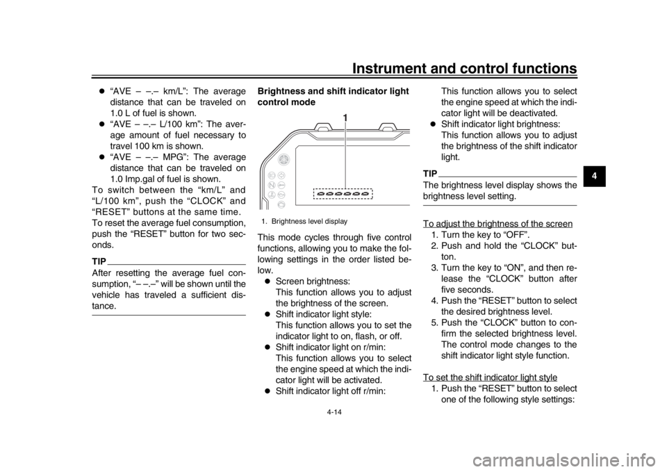
vehicle has traveled a sufficient dis-tance. Brightness and shift indicator light
control mode
This mode cycles through five control
functions, allowing you to make the fol-
lowing settings in the order listed be-
low.
Screen brightness:
This function allows you to adjust
the brightness of the screen.
Shift indicator light style:
This function allows you to set the
indicator light to on, flash, or off.
Shift indicator light on r/min:
This function allows you to select
the engine speed at which the indi-
cator light will be activated.
Shift indicator light off r/min:This function allows you to select
the engine speed at which the indi-
cator light will be deactivated.
Shift indicator light brightness:
This function allows you to adjust
the brightness of the shift indicator
light.
TIPThe brightness level display shows thebrightness level setting.
To adjust the brightness of the screen1. Turn the key to “OFF”.
2. Push and hold the “CLOCK” but-
ton.
3. Turn the key to “ON”, and then re- lease the “CLOCK” button after
five seconds.
4. Push the “RESET” button to select the desired brightness level.
5. Push the “CLOCK” button to con- firm the selected brightness level.
The control mode changes to the
shift indicator light style function.
To set the shift indicator light style1. Push the “RESET” button to select one of the following style settings:
1. Brightness level display
1
B67-9-E4.book 14 ページ 2019年7月19日 金曜日 午後4時23分
Page 39 of 108
Instrument and control functions
4-18
1
2
345
6
7
8
9
10
11
12
TIP
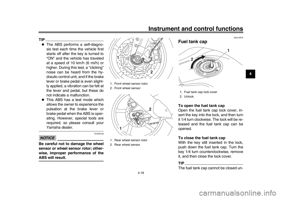
The ABS performs a self-diagno-
sis test each time the vehicle first
starts off after the key is turned to
“ON” and the vehicle has traveled
at a speed of 10 km/h (6 mi/h) or
higher. During this test, a “clicking”
noise can be heard from the hy-
draulic control unit, and if the brake
lever or brake pedal is even slight-
ly applied, a vibration can be felt at
the lever and pedal, but these do
not indicate a malfunction.
This ABS has a test mode which
allows the owner to experience the
pulsation at the brake lever or
brake pedal when the ABS is oper-
ating. However, special tools are
required, so please consult yourYamaha dealer.
NOTICE
ECA20100
Be careful not to damage the wheel
sensor or wheel sensor rotor; other-
wise, improper performance of theABS will result.
EAU13076
Fuel tank capTo open the fuel tank cap
Open the fuel tank cap lock cover, in-
sert the key into the lock, and then turn
it 1/4 turn clockwise. The lock will be re-
leased and the fuel tank cap can be
opened.
To close the fuel tank cap
With the key still inserted in the lock,
push down the fuel tank cap. Turn the
key 1/4 turn counterclockwise, remove
it, and then close the lock cover.TIPThe fuel tank cap cannot be closed un-
1. Front wheel sensor rotor
2. Front wheel sensor
1. Rear wheel sensor rotor
2. Rear wheel sensor
2
12
1
1. Fuel tank cap lock cover
2. Unlock.
1
2
B67-9-E4.book 18 ページ 2019年7月19日 金曜日 午後4時23分
Page 40 of 108
Instrument and control functions
4-19
1
2
34
5
6
7
8
9
10
11
12 less the key is in the lock. In addition,
the key cannot be removed if the cap is
not properly closed and locked.
WARNING
EWA11092
Make sure that the fuel tank cap is
properly closed after filling fuel.Leaking fuel is a fire hazard.
EAU13222
FuelMake sure there is sufficient gasoline in
the tank.
WARNING
EWA10882
Gasoline and gasoline vapors are
extremely flammable. To avoid fires
and explosions and to reduce the
risk of injury when refueling, followthese instructions.
1. Before refueling, turn off the en- gine and be sure that no one is sit-
ting on the vehicle. Never refuel
while smoking, or while in the vi-
cinity of sparks, open flames, or
other sources of ignition such as
the pilot lights of water heaters and
clothes dryers.
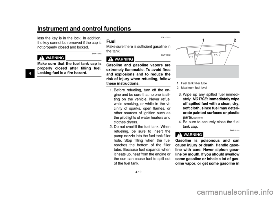
2. Do not overfill the fuel tank. When refueling, be sure to insert the
pump nozzle into the fuel tank filler
hole. Stop filling when the fuel
reaches the bottom of the filler
tube. Because fuel expands when
it heats up, heat from the engine or
the sun can cause fuel to spill out
of the fuel tank. 3. Wipe up any spilled fuel immedi-
ately. NOTICE: Immediately wipe
off spilled fuel with a clean, dry,
soft cloth, since fuel may deteri-
orate painted surfaces or plastic
parts.
[ECA10072]
4. Be sure to securely close the fuel tank cap.
WARNING
EWA15152
Gasoline is poisonous and can
cause injury or death. Handle gaso-
line with care. Never siphon gaso-
line by mouth. If you should swallow
some gasoline or inhale a lot of gas-
oline vapor, or get some gasoline in1. Fuel tank filler tube
2. Maximum fuel level
2
1
B67-9-E4.book 19 ページ 2019年7月19日 金曜日 午後4時23分
Page 43 of 108

Instrument and control functions
4-22
1
2
345
6
7
8
9
10
11
12
EAU57992
SeatTo remove the seat 1. Open the seat lock cover, insert the key into the seat lock, and then
turn the key counterclockwise.
2. While holding the key in that posi- tion, slide the seat backward and
then lift the rear of the seat up, and
then pull the seat off.
To install the seat 1. Insert the projections into the seat holders as shown. 2. Push the rear of the seat down to
lock it in place.
3. Remove the key.
TIPMake sure that the seat is properly se-cured before riding.
EAU70412
Adjusting the front forkThis model is equipped with adjustable
suspension. The spring preload, re-
bound damping force, and compres-
sion damping force of each leg can be
adjusted.
WARNING
EWA10181
Always adjust both fork legs equal-
ly, otherwise poor handling and lossof stability may result.NOTICE
ECA22471
Use extra care to avoid scratch-
ing the gold-anodized finish
when making suspension ad-
justments.
To avoid damaging the suspen-
sion’s internal mechanisms, do
not attempt to turn beyond themaximum or minimum settings.
Spring preload
To increase the spring preload and
thereby harden the suspension, turn
the adjusting nut on each fork in direc-
tion (a). To decrease the spring preload
1. Seat lock cover
2. Seat lock
3. Unlock.
2 3
1
1. Projection
2. Seat holder
2
2 1
B67-9-E4.book 22 ページ 2019年7月19日 金曜日 午後4時23分
Page 55 of 108
6-1
1
2
3
4
567
8
9
10
11
12
Operation and important riding points
EAU15952
Read the Owner’s Manual carefully to
become familiar with all controls. If
there is a control or function you do not
understand, ask your Yamaha dealer.
WARNING
EWA10272
Failure to familiarize yourself with
the controls can lead to loss of con-
trol, which could cause an accidentor injury.
EAUM3632
TIPThis model is equipped with:
a lean angle sensor. This sensor
stops the engine in case of a vehi-
cle turnover. If this happens, the
engine trouble warning light will
come on, but this is not a malfunc-
tion. Turn the vehicle power off
and then back on again to cancel
the warning light. Failing to do so
will prevent the engine from start-
ing even though the engine will
crank when pushing the start
switch.
an engine auto-stop system. The
engine stops automatically if left
idling for 20 minutes. If the engine
stops, simply push the start switchto restart the engine.
EAU74012
Starting the engineIn order for the ignition circuit cut-off
system to enable starting, one of the
following conditions must be met:
The transmission is in the neutral
position.
The transmission is in gear with
the clutch lever pulled and the sid-
estand up.
See page 4-29 for more informa-
tion.
1. Turn the key to “ON” and make sure that the stop/run/start switch
is set to “ ”.
The following warning lights and
indicator lights should come on for
a few seconds, then go off.
Oil pressure warning light
Engine trouble warning light
Coolant temperature warning
light
Shift indicator light
Steering damper warning light
Traction control system indica-
tor light
Cruise control indicator lights
Immobilizer system indicator
light
B67-9-E4.book 1 ページ 2019年7月19日 金曜日 午後4時23分
Page 56 of 108

Operation and important riding points
6-2
1
2
3
4
56
7
8
9
10
11
12
NOTICE
ECA11834
If a warning or indicator light does
not come on initially when the key is
turned to “ON”, or if a warning or in-
dicator light remains on, see page
4-5 for the corresponding warningand indicator light circuit check. The ABS warning light should
come on when the key is turned to
“ON”, and then go off after travel-
ing at a speed of 10 km/h (6 mi/h)
or higher.NOTICE
ECA17682
If the ABS warning light does not
come on and then go off as ex-
plained above, see page 4-5 for thewarning light circuit check.2. Shift the transmission into the neu- tral position. The neutral indicator
light should come on. If not, ask a
Yamaha dealer to check the elec-
trical circuit.
3. Start the engine by pushing the “ ” side of the stop/run/start
switch.
If the engine fails to start, release the stop/run/start switch, wait a
few seconds, and then try again.
Each starting attempt should be as
short as possible to preserve the
battery. Do not crank the engine
more than 10 seconds on any one
attempt.
NOTICE
ECA11043
For maximum engine life, never ac-
celerate hard when the engine iscold!
EAU77401
ShiftingShifting gears lets you control the
amount of engine power available for
starting off, accelerating, climbing hills,
etc. The gear positions are shown in
the illustration.TIP
To shift the transmission into the
neutral position ( ), press the
shift pedal down repeatedly until it
reaches the end of its travel, and
then slightly raise it.
This model is equipped with aquick shift system. (See page 3-6.)
1. Shift pedal
2. Gear positions
2
6
5
4
3
2
N 1
1
B67-9-E4.book 2 ページ 2019年7月19日 金曜日 午後4時23分
Page 58 of 108

Operation and important riding points
6-4
1
2
3
4
56
7
8
9
10
11
12 r/min.
1600 km (1000 mi) and beyond
The vehicle can now be operated nor-
mally.
NOTICE
ECA10311
Keep the engine speed out of
the tachometer red zone.
If any engine trouble should oc-
cur during the engine break-in
period, immediately have a
Yamaha dealer check the vehi-cle.
TIPDuring and after the engine break-in
period, the exhaust heat may cause
discoloration of the exhaust pipe, butthis is normal.
EAU17214
ParkingWhen parking, stop the engine, and
then remove the key from the main
switch.
WARNING
EWA10312
Since the engine and exhaust
system can become very hot,
park in a place where pedestri-
ans or children are not likely to
touch them and be burned.
Do not park on a slope or on soft
ground, otherwise the vehicle
may overturn, increasing the
risk of a fuel leak and fire.
Do not park near grass or other
flammable materials whichmight catch fire.
B67-9-E4.book 4 ページ 2019年7月19日 金曜日 午後4時23分
Page 90 of 108

Periodic maintenance and adjustment
7-32
1
2
3
4
5
67
8
9
10
11
12 3. Place the panels in the original po-
sition.
4. Install the washers, bolts and quick fasteners.
TIPThe quick fasteners are installed by
pushing out the center pin, inserting the
fastener into the panel, and then by
pushing the center pin flush with thefastener head. If a fuse is blown, replace it as follows.
1. Turn the key to “OFF” and turn off the electrical circuit in question.
2. Remove the blown fuse, and then install a new fuse of the specified
amperage. WARNING! Do not
use a fuse of a higher amperage
rating than recommended to
avoid causing extensive dam-
age to the electrical system and
possibly a fire.
[EWA15132]
1. Ignition fuse
2. Signaling system fuse
3. ABS ECU fuse
4. Headlight fuse
5. Hazard fuse
6. Terminal fuse 1 (for auxiliary DC jack)
7. Spare fuse
7 1
2
3
4
5
6
1. ABS solenoid fuse
2. Fuel injection system fuse
3. Electronic throttle valve fuse
4. Backup fuse
5. Sub radiator fan motor fuse
6. Radiator fan motor fuse
7. Spare fuse
7
1
2
3
4
5
6
B67-9-E4.book 32 ページ 2019年7月19日 金曜日 午後4時23分
Page 91 of 108
Periodic maintenance and adjustment7-33
1
2
3
4
5
678
9
10
11
12
3. Turn the key to “ON” and turn on
the electrical circuit in question to
check if the device operates.
4. If the fuse immediately blows again, have a Yamaha dealer
check the electrical system.
EAU72980
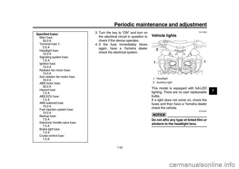
Vehicle lightsThis model is equipped with full-LED
lighting. There are no user replaceable
bulbs.
If a light does not come on, check the
fuses and then have a Yamaha dealer
check the vehicle.NOTICE
ECA16581
Do not affix any type of tinted film orstickers to the headlight lens.
Specified fuses:Main fuse: 50.0 A
Terminal fuse 1:
2.0 A
Headlight fuse: 10.0 A
Signaling system fuse: 7.5 A
Ignition fuse:
15.0 A
Radiator fan motor fuse: 15.0 A
Sub radiator fan motor fuse: 10.0 A
ABS motor fuse:
30.0 A
Hazard fuse: 7.5 A
ABS ECU fuse: 7.5 A
ABS solenoid fuse:
10.0 A
Fuel injection system fuse: 15.0 A
Backup fuse: 7.5 A
Electronic throttle valve fuse: 7.5 A
Brake light fuse: 1.0 A
Cruise control fuse:
1.0 A
1. Headlight
2. Auxiliary light1 12
B67-9-E4.book 33 ページ 2019年7月19日 金曜日 午後4時23分