low oil pressure YAMAHA MT-10 2020 Owners Manual
[x] Cancel search | Manufacturer: YAMAHA, Model Year: 2020, Model line: MT-10, Model: YAMAHA MT-10 2020Pages: 108, PDF Size: 9.22 MB
Page 26 of 108

Instrument and control functions
4-5
1
2
34
5
6
7
8
9
10
11
12
EAU4939G
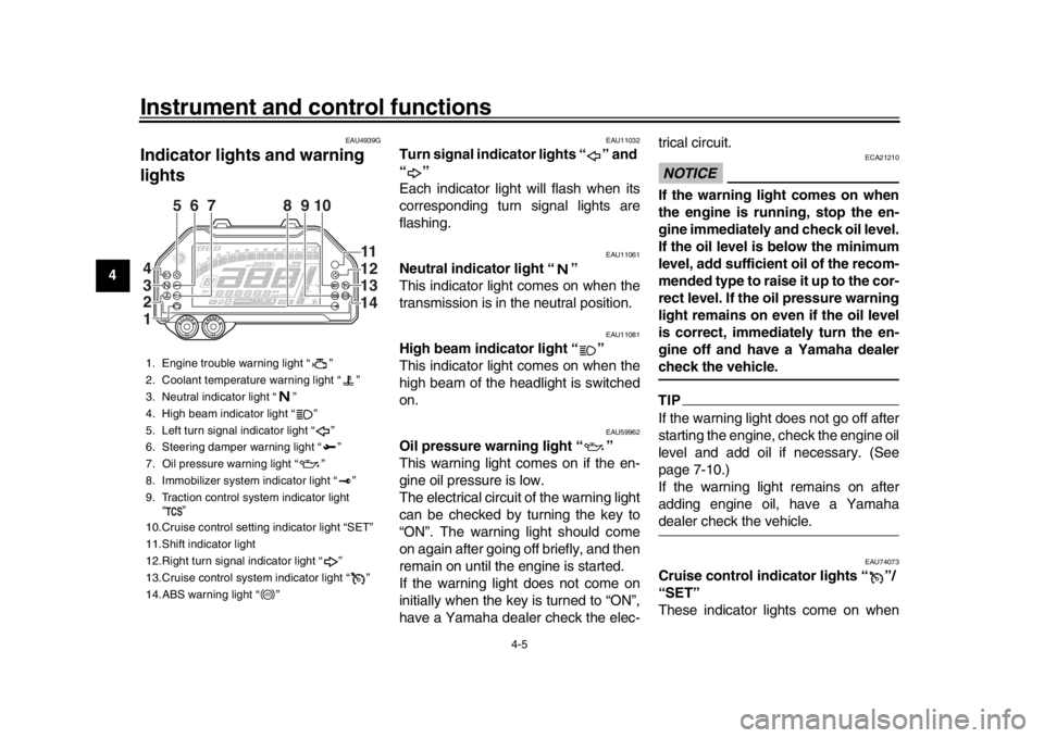
Indicator ligh ts and warning
lights
EAU11032
Turn signal indicator lights “ ” and
“”
Each indicator light will flash when its
corresponding turn signal lights are
flashing.
EAU11061
Neutral indicator light “ ”
This indicator light comes on when the
transmission is in the neutral position.
EAU11081
High beam indicator light “ ”
This indicator light comes on when the
high beam of the headlight is switched
on.
EAU59962
Oil pressure warning light “ ”
This warning light comes on if the en-
gine oil pressure is low.
The electrical circuit of the warning light
can be checked by turning the key to
“ON”. The warning light should come
on again after going off briefly, and then
remain on until the engine is started.
If the warning light does not come on
initially when the key is turned to “ON”,
have a Yamaha dealer check the elec- trical circuit.
NOTICE
ECA21210
If the warning light comes on when
the engine is running, stop the en-
gine immediately and check oil level.
If the oil level is below the minimum
level, add sufficient oil of the recom-
mended type to raise it up to the cor-
rect level. If the oil pressure warning
light remains on even if the oil level
is correct, immediately turn the en-
gine off and have a Yamaha dealercheck the vehicle.TIPIf the warning light does not go off after
starting the engine, check the engine oil
level and add oil if necessary. (See
page 7-10.)
If the warning light remains on after
adding engine oil, have a Yamahadealer check the vehicle.
EAU74073
Cruise control indicator lights “ ”/
“SET”
These indicator lights come on when
1. Engine trouble warning light “ ”
2. Coolant temperature warning light “ ”
3. Neutral indicator light “ ”
4. High beam indicator light “ ”
5. Left turn signal indicator light “ ”
6. Steering damper warning light “ ”
7. Oil pressure warning light “ ”
8. Immobilizer system indicator light “ ”
9. Traction control system indicator light
“”
10.Cruise control setting indicator light “SET”
11.Shift indicator light
12.Right turn signal indicator light “ ”
13.Cruise control system indicator light “ ”
14.ABS warning light “ ”
567 9 810
11
12
13
14
4
3
2
1
ABS
B67-9-E4.book 5 ページ 2019年7月19日 金曜日 午後4時23分
Page 55 of 108

6-1
1
2
3
4
567
8
9
10
11
12
Operation and important riding points
EAU15952
Read the Owner’s Manual carefully to
become familiar with all controls. If
there is a control or function you do not
understand, ask your Yamaha dealer.
WARNING
EWA10272
Failure to familiarize yourself with
the controls can lead to loss of con-
trol, which could cause an accidentor injury.
EAUM3632
TIPThis model is equipped with:
a lean angle sensor. This sensor
stops the engine in case of a vehi-
cle turnover. If this happens, the
engine trouble warning light will
come on, but this is not a malfunc-
tion. Turn the vehicle power off
and then back on again to cancel
the warning light. Failing to do so
will prevent the engine from start-
ing even though the engine will
crank when pushing the start
switch.
an engine auto-stop system. The
engine stops automatically if left
idling for 20 minutes. If the engine
stops, simply push the start switchto restart the engine.
EAU74012
Starting the engineIn order for the ignition circuit cut-off
system to enable starting, one of the
following conditions must be met:
The transmission is in the neutral
position.
The transmission is in gear with
the clutch lever pulled and the sid-
estand up.
See page 4-29 for more informa-
tion.
1. Turn the key to “ON” and make sure that the stop/run/start switch
is set to “ ”.
The following warning lights and
indicator lights should come on for
a few seconds, then go off.
Oil pressure warning light
Engine trouble warning light
Coolant temperature warning
light
Shift indicator light
Steering damper warning light
Traction control system indica-
tor light
Cruise control indicator lights
Immobilizer system indicator
light
B67-9-E4.book 1 ページ 2019年7月19日 金曜日 午後4時23分
Page 82 of 108

Periodic maintenance and adjustment
7-24
1
2
3
4
5
67
8
9
10
11
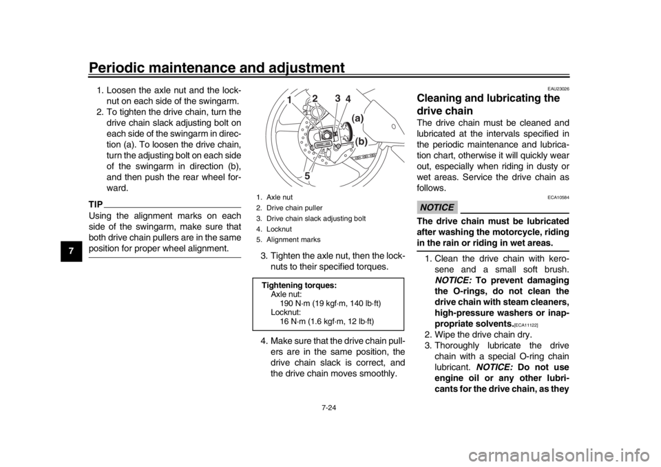
12 1. Loosen the axle nut and the lock-
nut on each side of the swingarm.
2. To tighten the drive chain, turn the drive chain slack adjusting bolt on
each side of the swingarm in direc-
tion (a). To loosen the drive chain,
turn the adjusting bolt on each side
of the swingarm in direction (b),
and then push the rear wheel for-
ward.
TIPUsing the alignment marks on each
side of the swingarm, make sure that
both drive chain pullers are in the sameposition for proper wheel alignment. 3. Tighten the axle nut, then the lock-
nuts to their specified torques.
4. Make sure that the drive chain pull- ers are in the same position, the
drive chain slack is correct, and
the drive chain moves smoothly.
EAU23026
Cleaning and lubricating the
drive chainThe drive chain must be cleaned and
lubricated at the intervals specified in
the periodic maintenance and lubrica-
tion chart, otherwise it will quickly wear
out, especially when riding in dusty or
wet areas. Service the drive chain as
follows.NOTICE
ECA10584
The drive chain must be lubricated
after washing the motorcycle, ridingin the rain or riding in wet areas.
1. Clean the drive chain with kero- sene and a small soft brush.
NOTICE: To prevent damaging
the O-rings, do not clean the
drive chain with steam cleaners,
high-pressure washers or inap-
propriate solvents.
[ECA11122]
2. Wipe the drive chain dry.
3. Thoroughly lubricate the drive chain with a special O-ring chain
lubricant. NOTICE: Do not use
engine oil or any other lubri-
cants for the drive chain, as they
1. Axle nut
2. Drive chain puller
3. Drive chain slack adjusting bolt
4. Locknut
5. Alignment marksTightening torques: Axle nut:190 N·m (19 kgf·m, 140 lb·ft)
Locknut: 16 N·m (1.6 kgf·m, 12 lb·ft)
1
2 3
45
(a)
(b)
B67-9-E4.book 24 ページ 2019年7月19日 金曜日 午後4時23分
Page 96 of 108

Motorcycle care and storage
8-2
1
2
3
4
5
6
78
9
10
11
12 gasoline, rust removers, brake
fluid, or antifreeze, etc.
Before washing 1. Park the vehicle out of direct sun- light and allow it to cool. This will
help avoid water spots.
2. Make sure all caps, covers, electri- cal couplers and connectors are
tightly installed.
3. Cover the muffler end with a plas- tic bag and a strong rubber band.
4. Pre-soak stubborn stains like in- sects or bird droppings with a wet
towel for a few minutes.
5. Remove road grime and oil stains with a quality degreasing agent
and a plastic-bristle brush or
sponge. NOTICE: Do not use de-
greasing agent on areas requir-
ing lubrication such as seals,
gaskets, and wheel axles. Fol-
low product instructions.
[ECA26290]
Washing 1. Rinse off any degreaser and spray down the vehicle with a garden
hose. Use only enough pressure to do the job. Avoid spraying water
directly into the muffler, instrument
panel, air inlet, or other inner areas
such as underseat storage com-
partments.
2. Wash the vehicle with a quality au- tomotive-type detergent mixed
with cool water and a soft, clean
towel or sponge. Use an old tooth-
brush or plastic-bristle brush for
hard-to-reach places. NOTICE:
Use cold water if the vehicle has
been exposed to salt. Warm wa-
ter will increase salt’s corrosive
properties.
[ECA26301]
3. For windshield-equipped vehicles: Clean the windshield with a soft
towel or sponge dampened with
water and a pH neutral detergent.
If necessary, use a high-quality
windshield cleaner or polish for
motorcycles. NOTICE: Never use
any strong chemicals to clean
the windshield. Additionally,
some cleaning compounds for
plastic may scratch the wind-
shield, so be sure to test all
cleaning products before gener-
al application.
[ECA26310]
4. Rinse off thoroughly with clean wa- ter. Be sure to remove all deter-
gent residues, as they can be
harmful to plastic parts.
After washing 1. Dry the vehicle with a chamois or
absorbent towel, preferably micro-
fiber terrycloth.
2. For drive chain-equipped models: Dry and then lubricate the drive
chain to prevent rust.
3. Use a chrome polish to shine chrome, aluminum, and stainless
steel parts. Often the thermally in-
duced discoloring of stainless steel
exhaust systems can be removed
through polishing.
4. Apply a corrosion protection spray on all metal parts including chrome
or nickel-plated surfaces.
WARNING! Do not apply
silicone or oil spray to seats,
hand grips, rubber foot pegs or
tire treads. Otherwise these
parts will become slippery,
which could cause loss of con-
trol. Thoroughly clean the sur-
faces of these parts before
B67-9-E4.book 2 ページ 2019年7月19日 金曜日 午後4時23分
Page 105 of 108

11-1
1
2
3
4
5
6
7
8
9
101112
Index
AABS ...................................................... 4-17
ABS warning light ................................... 4-6
Air filter element.................................... 7-15
Auxiliary DC jack .................................. 4-27BBattery .................................................. 7-29
Brake and clutch levers, checking and lubricating .................................... 7-26
Brake and shift pedals, checking
and lubricating .................................... 7-26
Brake fluid, changing ............................ 7-23
Brake fluid level, checking .................... 7-22
Brake lever ........................................... 4-16
Brake lever free play, checking ............ 7-20
Brake light switches .............................. 7-21
Brake pedal .......................................... 4-17CCables, checking and lubricating .......... 7-25
Canister ................................................ 7-10
Care ........................................................ 8-1
Catalytic converter ................................ 4-21
Clutch lever........................................... 4-16
Clutch lever free play, adjusting ........... 7-19
Coolant ................................................. 7-14
Coolant temperature warning light.......... 4-6
Cruise control indicator lights ................. 4-5
Cruise control switches........................... 4-4
Cruise control system ............................. 3-1DData recording, vehicle ......................... 10-2
Diagnostic connecto r ............................ 10-2
Dimmer/Pass switch ............................... 4-3
D-mode (drive mode).............................. 3-3 Drive chain, cleaning
and lubricating .... 7-24
Drive chain slack ................................... 7-23
Drive mode switch ................................... 4-4
EEngine break-in ....................................... 6-3
Engine idling speed, checking............... 7-16
Engine oil .............................................. 7-10
Engine serial number ............................ 10-1
Engine trouble warning light .................... 4-6
EXUP system ........................................ 4-27FFront and rear brake pads, checking .... 7-21
Front fork, adjusting .............................. 4-22
Front fork, checking............................... 7-28
Fuel ....................................................... 4-19
Fuel consumption, tips for reducing ........6-3
Fuel tank cap......................................... 4-18
Fuel tank overflow hose ........................ 4-21
Fuses, replacing .................................... 7-30HHandlebar switches ................................. 4-3
Hazard switch.......................................... 4-4
High beam indicator light .........................4-5
Horn switch .............................................4-4IIdentification numbers ........................... 10-1
Ignition circuit cut-off system ................. 4-29
Immobilizer system ................................. 4-1
Immobilizer system indicator light ........... 4-7
Indicator lights and warning lights ........... 4-5LLuggage strap holders .......................... 4-27MMain switch/steering lock ........................4-2 Maintenance and lubrication, periodic .... 7-5
Maintenance, emission control
system .................................................. 7-3
Matte color, caution ................................ 8-1
Model label ........................................... 10-2
Multi-function meter unit ......................... 4-8
NNeutral indicator light .............................. 4-5OOil pressure warning light ....................... 4-5PParking.................................................... 6-4
Part locations .......................................... 2-1QQuick shift system................................... 3-6SSafety information ................................... 1-1
Seat ...................................................... 4-22
SELECT switch ....................................... 4-4
Shift indicator light .................................. 4-7
Shifting .................................................... 6-2
Shift pedal ............................................. 4-16
Shock absorber assembly, adjusting .... 4-24
Sidestand .............................................. 4-28
Sidestand, checking and lubricating ..... 7-27
Spark plugs, checking ............................. 7-9
Special features ...................................... 3-1
Specifications.......................................... 9-1
Starting the engine.................................. 6-1
Steering, checking ................................ 7-28
Steering damper warning light ................ 4-7
Stop/Run/Start switch ............................. 4-4
Storage ................................................... 8-4
Supporting the motorcycle .................... 7-34
B67-9-E4.book 1 ページ 2019年7月19日 金曜日 午後4時23分