Level YAMAHA MT-125 2018 Owners Manual
[x] Cancel search | Manufacturer: YAMAHA, Model Year: 2018, Model line: MT-125, Model: YAMAHA MT-125 2018Pages: 96, PDF Size: 7.1 MB
Page 5 of 96

Table of contents
Safety information............................1-1
Description........................................2-1
Left view ..........................................2-1
Right view........................................2-2
Controls and instruments ................2-3
Instrument and control functions....3-1
Main switch/steering lock ...............3-1
Indicator lights and warning
lights ............................................3-2
Multi-function meter unit .................3-4
Handlebar switches.......................3-12
Clutch lever ...................................3-13
Shift pedal .....................................3-14
Brake lever ....................................3-14
Brake pedal ...................................3-15
ABS ...............................................3-15
Fuel tank cap.................................3-16
Fuel................................................3-17
Catalytic converter ........................3-18
Rider seat ......................................3-19
Sidestand ......................................3-20
Ignition circuit cut-off system........3-20
For your safety – pre-operation
checks...............................................4-1
Operation and important riding
points.................................................5-1
Starting the engine ..........................5-2
Shifting ............................................5-3
Tips for reducing fuel
consumption ................................5-4
Engine break-in ...............................5-4
Parking ............................................5-5
Periodic maintenance and
adjustment........................................6-1
Owner’s tool kit ...............................6-2
Periodic maintenance chart for the
emission control system ..............6-3
General maintenance and
lubrication chart ...........................6-4
Removing and installing cowlings ...6-7
Checking the spark plug .................6-8Engine oil and oil filter element ....... 6-9
Coolant ......................................... 6-12
Replacing the air filter element
and cleaning the check hose..... 6-14
Checking the engine idling
speed......................................... 6-14
Adjusting the throttle grip free
play ............................................ 6-15
Valve clearance ............................. 6-16
Tires .............................................. 6-16
Cast wheels .................................. 6-19
Adjusting the clutch lever free
play ............................................ 6-19
Checking the front brake lever
free play ..................................... 6-20
Adjusting the brake pedal free
play ............................................ 6-21
Brake light switches ...................... 6-21
Checking the front and rear brake
pads........................................... 6-22
Checking the brake fluid level....... 6-23
Changing the brake fluid............... 6-24
Drive chain slack ........................... 6-24
Cleaning and lubricating the drive
chain .......................................... 6-26
Checking and lubricating the
cables ........................................ 6-26
Checking and lubricating the
throttle grip and cable ............... 6-27
Checking and lubricating the
brake and clutch levers ............. 6-27
Checking and lubricating the
brake pedal................................ 6-28
Checking and lubricating the
sidestand ................................... 6-28
Lubricating the swingarm
pivots ......................................... 6-29
Checking the front fork ................. 6-29
Checking the steering ................... 6-30
Checking the wheel bearings ....... 6-30
Battery .......................................... 6-31
Replacing the fuses ...................... 6-32
Replacing the headlight bulb ........ 6-33
Auxiliary lights ............................... 6-35
Tail/brake light .............................. 6-35
UBR3E1E0.book Page 1 Wednesday, August 10, 2016 9:45 AM
Page 9 of 96

Safety information
1-3
1 Avoid Carbon Monoxide Poisoning
All engine exhaust contains carbon
monoxide, a deadly gas. Breathing
carbon monoxide can cause head-
aches, dizziness, drowsiness, nausea,
confusion, and eventually death.
Carbon Monoxide is a colorless, odor-
less, tasteless gas which may be pres-
ent even if you do not see or smell any
engine exhaust. Deadly levels of car-
bon monoxide can collect rapidly and
you can quickly be overcome and un-
able to save yourself. Also, deadly lev-
els of carbon monoxide can linger for
hours or days in enclosed or poorly
ventilated areas. If you experience any
symptoms of carbon monoxide poi-
soning, leave the area immediately, get
fresh air, and SEEK MEDICAL TREAT-
MENT.
Do not run engine indoors. Even if
you try to ventilate engine exhaust
with fans or open windows and
doors, carbon monoxide can rap-
idly reach dangerous levels.
Do not run engine in poorly venti-
lated or partially enclosed areas
such as barns, garages, or car-
ports.
Do not run engine outdoors where
engine exhaust can be drawn into
a building through openings such
as windows and doors.
Loading
Adding accessories or cargo to your
motorcycle can adversely affect stabil-
ity and handling if the weight distribu-
tion of the motorcycle is changed. To
avoid the possibility of an accident, use
extreme caution when adding cargo or
accessories to your motorcycle. Useextra care when riding a motorcycle
that has added cargo or accessories.
Here, along with the information about
accessories below, are some general
guidelines to follow if loading cargo to
your motorcycle:
The total weight of the operator, pas-
senger, accessories and cargo must
not exceed the maximum load limit.
Operation of an overloaded vehicle
could cause an accident.
When loading within this weight limit,
keep the following in mind:
Cargo and accessory weight
should be kept as low and close to
the motorcycle as possible. Se-
curely pack your heaviest items as
close to the center of the vehicle
as possible and make sure to dis-
tribute the weight as evenly as
possible on both sides of the mo-
torcycle to minimize imbalance or
instability.
Shifting weights can create a sud-
den imbalance. Make sure that
accessories and cargo are se-
curely attached to the motorcycle
before riding. Check accessory
mounts and cargo restraints fre-
quently.
• Properly adjust the suspension
for your load (suspension-ad-
justable models only), and
check the condition and pres-
sure of your tires.
• Never attach any large or heavy
items to the handlebar, front
fork, or front fender. These
items, including such cargo as
Maximum load:
180 kg (397 lb)
UBR3E1E0.book Page 3 Wednesday, August 10, 2016 9:45 AM
Page 16 of 96
Instrument and control functions
3-2
3From the “LOCK” position, push the
key and turn it to “OFF”.
EAU49399
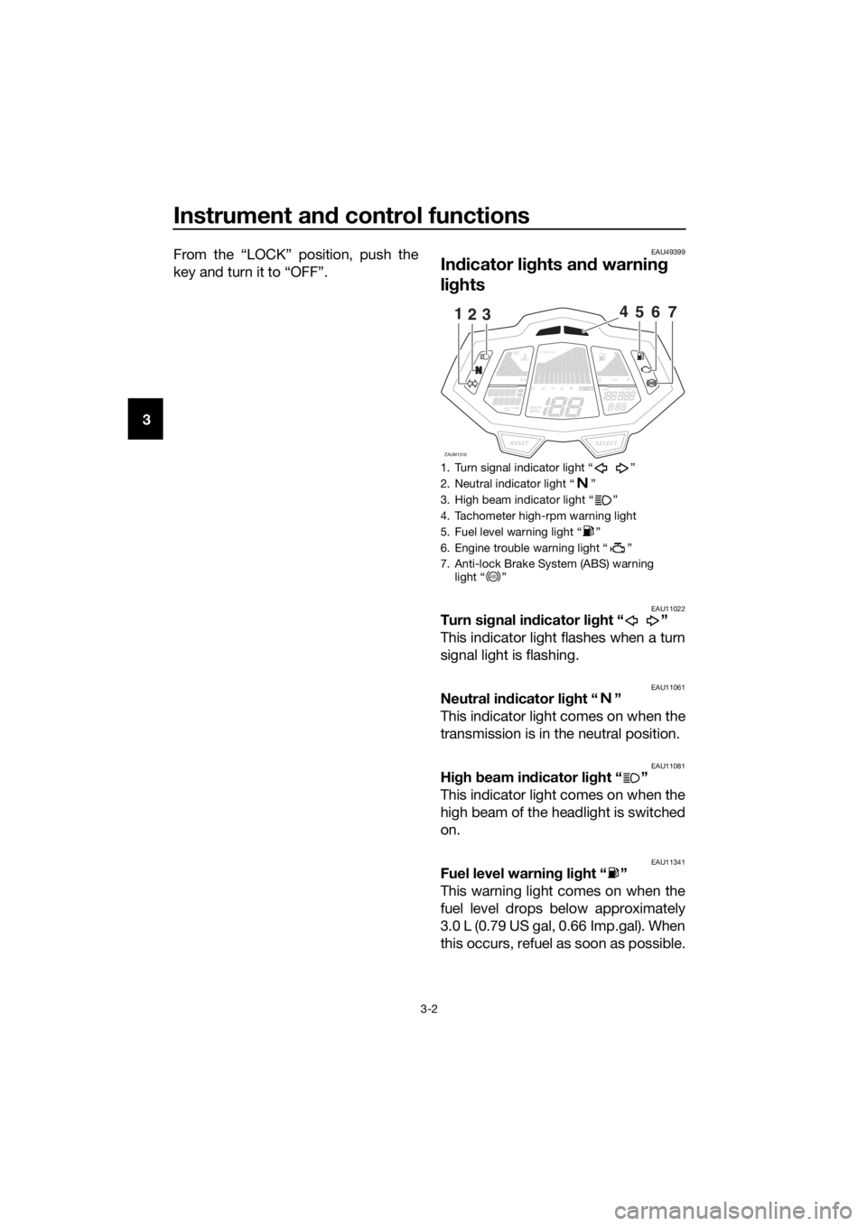
Indicator lights and warning
lights
EAU11022Turn signal indicator light “ ”
This indicator light flashes when a turn
signal light is flashing.
EAU11061Neutral indicator light “ ”
This indicator light comes on when the
transmission is in the neutral position.
EAU11081High beam indicator light “ ”
This indicator light comes on when the
high beam of the headlight is switched
on.
EAU11341Fuel level warning light “ ”
This warning light comes on when the
fuel level drops below approximately
3.0 L (0.79 US gal, 0.66 Imp.gal). When
this occurs, refuel as soon as possible.
1. Turn signal indicator light “ ”
2. Neutral indicator light “ ”
3. High beam indicator light “ ”
4. Tachometer high-rpm warning light
5. Fuel level warning light “ ”
6. Engine trouble warning light “ ”
7. Anti-lock Brake System (ABS) warning
light “ ”
Lo
Hi
1/2
x1000r/min
ZAUM1316SELECTRESET
km/L/100kmMPGkm/h
MPH
ODOFTRIP12OILOIL
1235467
ABS
UBR3E1E0.book Page 2 Wednesday, August 10, 2016 9:45 AM
Page 20 of 96
Instrument and control functions
3-6
32. Push the “SELECT” button for two
seconds, and the hour digits will
start flashing.
3. Use the “RESET” button to set the
hours.
4. Push the “SELECT” button, and
the minute digits will start flashing.
5. Use the “RESET” button to set the
minutes.
6. Push the “SELECT” button to con-
firm settings and start the clock.
TIP
When setting the hours and minutes, a
creases the increment value one by
one. You may also push and hold the
button to increase the value continu-
ously.
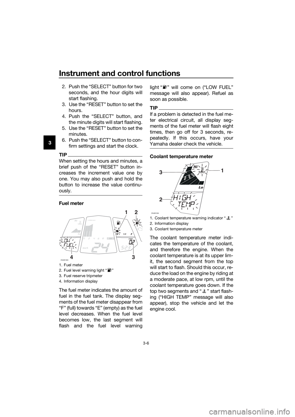
Fuel meter
The fuel meter indicates the amount of
fuel in the fuel tank. The display seg-
ments of the fuel meter disappear from
“F” (full) towards “E” (empty) as the fuel
level decreases. When the fuel level
becomes low, the last segment will
flash and the fuel level warninglight “ ” will come on (“LOW FUEL”
message will also appear). Refuel as
soon as possible.
TIP
If a problem is detected in the fuel me-
ter electrical circuit, all display seg-
ments of the fuel meter will flash eight
times, then go off for 3 seconds, re-
peatedly. If this occurs, have your
Yamaha dealer check the vehicle.
Coolant temperature meter
The coolant temperature meter indi-
cates the temperature of the coolant,
and therefore the engine. When the
coolant temperature is at its upper lim-
it, the second segment from the top
will start to flash. Should this occur, re-
duce the load on the engine by riding at
a moderate pace, at low rpm, until the
coolant temperature goes down. If the
top two segments and “ ” start flash-
ing (“HIGH TEMP” message will also
appear), stop the vehicle and let the
engine cool.
1. Fuel meter
2. Fuel level warning light “ ”
3. Fuel reserve tripmeter
4. Information display
Lo
Hi
1/2
x1000r/min
ZAUM1303
km/h
FTRIP
21
34
1. Coolant temperature warning indicator Ž
2. Information display
3. Coolant temperature meter
Lo
Hi
ZAUM1304
31
2
UBR3E1E0.book Page 6 Wednesday, August 10, 2016 9:45 AM
Page 31 of 96
Instrument and control functions
3-17
3
EAU13213
Fuel
Make sure there is sufficient gasoline in
the tank.
WARNING
EWA10882
Gasoline and gasoline vapors are
extremely flammable. To avoid fires
and explosions and to reduce the
risk of injury when refueling, follow
these instructions.
1. Before refueling, turn off the en-
gine and be sure that no one is sit-
ting on the vehicle. Never refuel
while smoking, or while in the vi-
cinity of sparks, open flames, or
other sources of ignition such as
the pilot lights of water heaters
and clothes dryers.
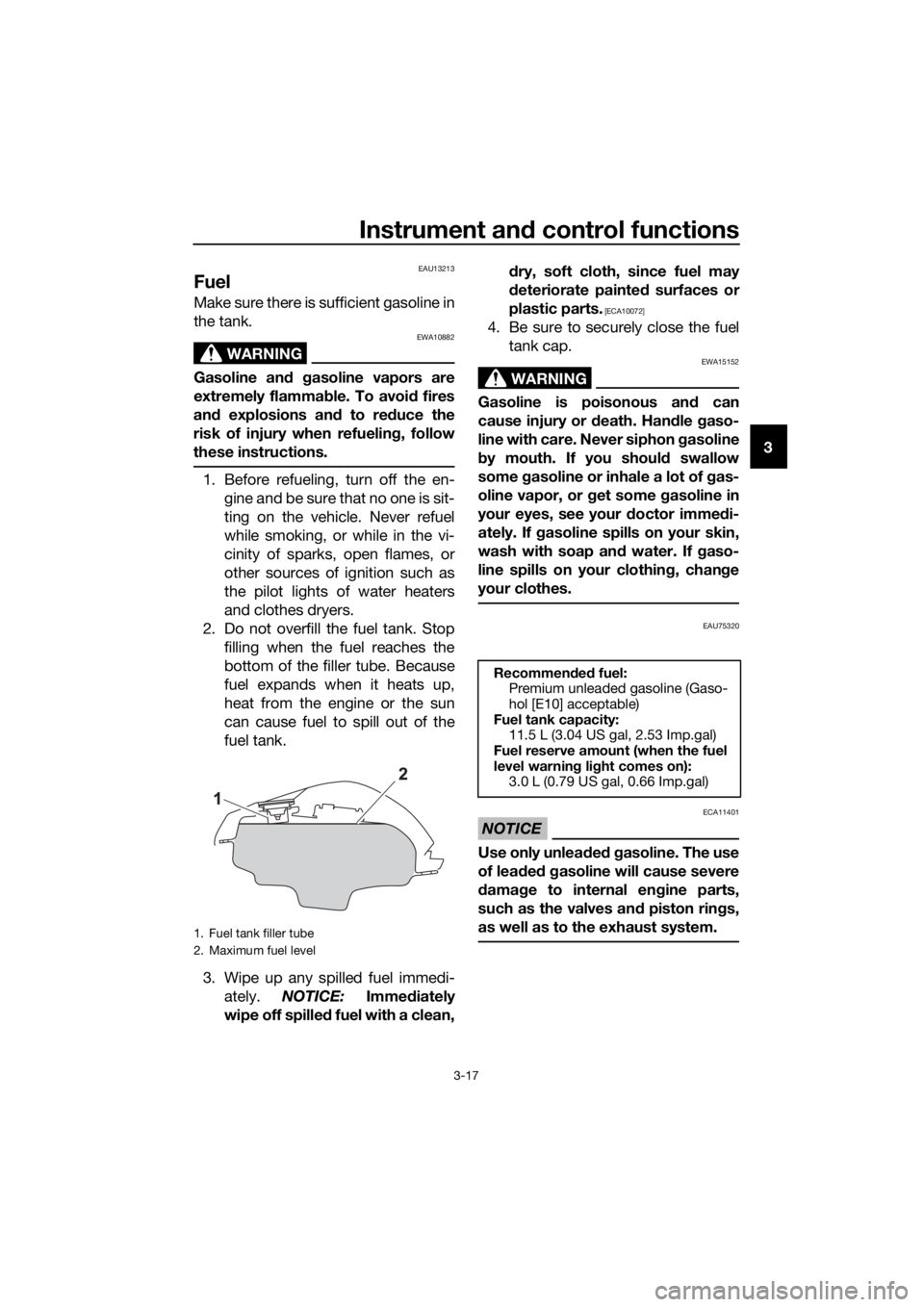
2. Do not overfill the fuel tank. Stop
filling when the fuel reaches the
bottom of the filler tube. Because
fuel expands when it heats up,
heat from the engine or the sun
can cause fuel to spill out of the
fuel tank.
3. Wipe up any spilled fuel immedi-
ately. NOTICE: Immediately
wipe off spilled fuel with a clean,dry, soft cloth, since fuel may
deteriorate painted surfaces or
plastic parts.
[ECA10072]
4. Be sure to securely close the fuel
tank cap.
WARNING
EWA15152
Gasoline is poisonous and can
cause injury or death. Handle gaso-
line with care. Never siphon gasoline
by mouth. If you should swallow
some gasoline or inhale a lot of gas-
oline vapor, or get some gasoline in
your eyes, see your doctor immedi-
ately. If gasoline spills on your skin,
wash with soap and water. If gaso-
line spills on your clothing, change
your clothes.
EAU75320
NOTICE
ECA11401
Use only unleaded gasoline. The use
of leaded gasoline will cause severe
damage to internal engine parts,
such as the valves and piston rings,
as well as to the exhaust system.
1. Fuel tank filler tube
2. Maximum fuel level
Recommended fuel:
Premium unleaded gasoline (Gaso-
hol [E10] acceptable)
Fuel tank capacity:
11.5 L (3.04 US gal, 2.53 Imp.gal)
Fuel reserve amount (when the fuel
level warning light comes on):
3.0 L (0.79 US gal, 0.66 Imp.gal)
UBR3E1E0.book Page 17 Wednesday, August 10, 2016 9:45 AM
Page 36 of 96
For your safety – pre-operation checks
4-1
4
EAU63440
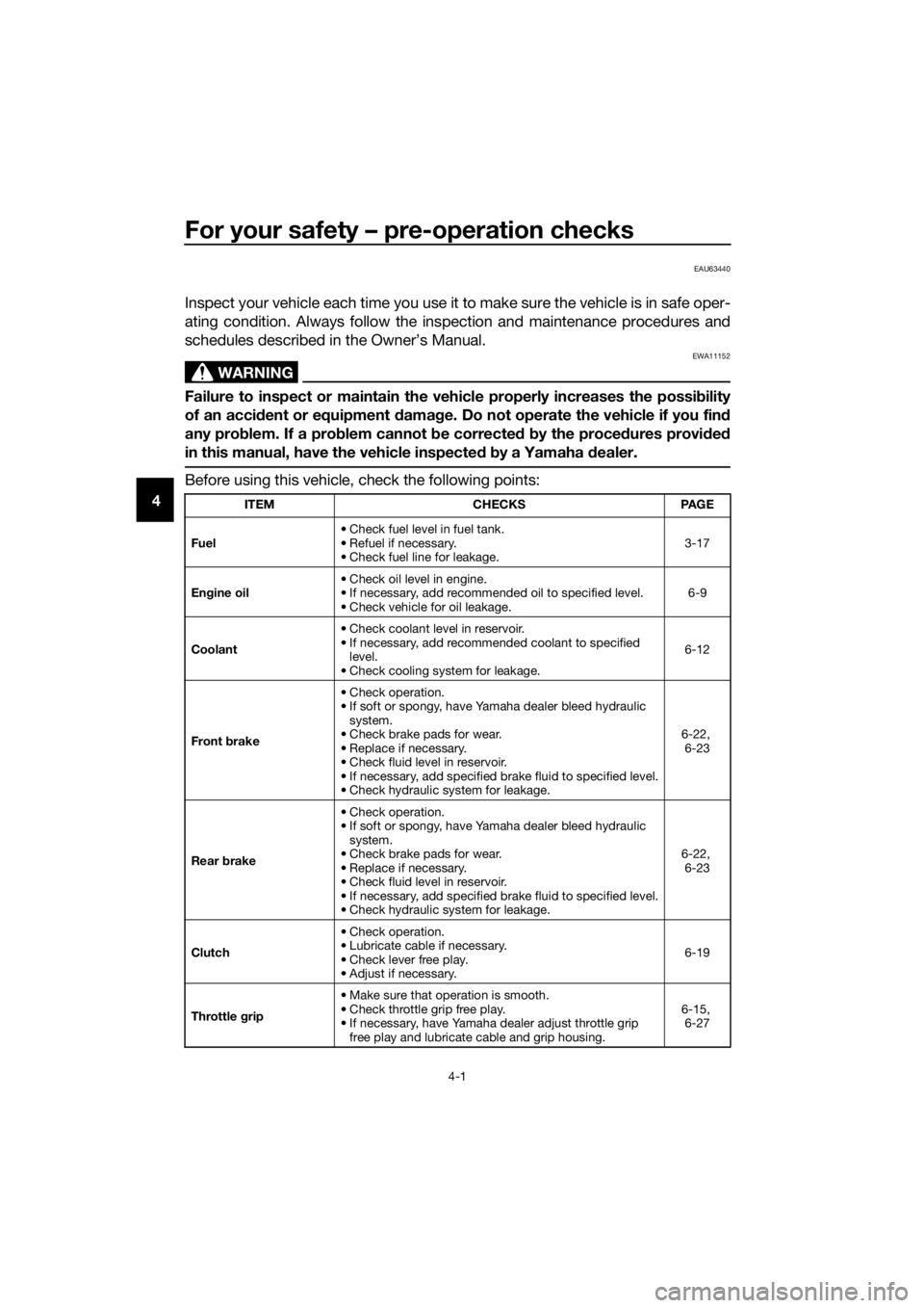
Inspect your vehicle each time you use it to make sure the vehicle is in safe oper-
ating condition. Always follow the inspection and maintenance procedures and
schedules described in the Owner’s Manual.
WARNING
EWA11152
Failure to inspect or maintain the vehicle properly increases the possibility
of an accident or equipment damage. Do not operate the vehicle if you find
any problem. If a problem cannot be corrected by the procedures provided
in this manual, have the vehicle inspected by a Yamaha dealer.
Before using this vehicle, check the following points:
ITEM CHECKS PAGE
Fuel• Check fuel level in fuel tank.
• Refuel if necessary.
• Check fuel line for leakage.3-17
Engine oil• Check oil level in engine.
• If necessary, add recommended oil to specified level.
• Check vehicle for oil leakage.6-9
Coolant• Check coolant level in reservoir.
• If necessary, add recommended coolant to specified
level.
• Check cooling system for leakage.6-12
Front brake• Check operation.
• If soft or spongy, have Yamaha dealer bleed hydraulic
system.
• Check brake pads for wear.
• Replace if necessary.
• Check fluid level in reservoir.
• If necessary, add specified brake fluid to specified level.
• Check hydraulic system for leakage.6-22,
6-23
Rear brake• Check operation.
• If soft or spongy, have Yamaha dealer bleed hydraulic
system.
• Check brake pads for wear.
• Replace if necessary.
• Check fluid level in reservoir.
• If necessary, add specified brake fluid to specified level.
• Check hydraulic system for leakage.6-22,
6-23
Clutch• Check operation.
• Lubricate cable if necessary.
• Check lever free play.
• Adjust if necessary.6-19
Throttle grip• Make sure that operation is smooth.
• Check throttle grip free play.
• If necessary, have Yamaha dealer adjust throttle grip
free play and lubricate cable and grip housing.6-15,
6-27
UBR3E1E0.book Page 1 Wednesday, August 10, 2016 9:45 AM
Page 37 of 96

For your safety – pre-operation checks
4-2
4
Control cables• Make sure that operation is smooth.
• Lubricate if necessary.6-26
Drive chain• Check chain slack.
• Adjust if necessary.
• Check chain condition.
• Lubricate if necessary.6-24,
6-26
Wheels and tires•Check for damage.
• Check tire condition and tread depth.
• Check air pressure.
• Correct if necessary.6-16,
6-19
Brake pedal• Make sure that operation is smooth.
• Lubricate pedal pivoting point if necessary.6-28
Brake and clutch le-
vers• Make sure that operation is smooth.
• Lubricate lever pivoting points if necessary.6-27
Sidestand• Make sure that operation is smooth.
• Lubricate pivot if necessary.6-28
Chassis fasteners• Make sure that all nuts, bolts and screws are properly
tightened.
• Tighten if necessary.—
Instruments, lights,
signals and switches• Check operation.
• Correct if necessary.—
Sidestand switch • Check operation of ignition circuit cut-off system.
• If system is not working correctly, have Yamaha dealer
check vehicle.3-20
Battery• Check fluid level.
• Fill with distilled water if necessary.6-31 ITEM CHECKS PAGE
UBR3E1E0.book Page 2 Wednesday, August 10, 2016 9:45 AM
Page 39 of 96
Operation and important riding points
5-2
5
EAUM3531
Starting the engine
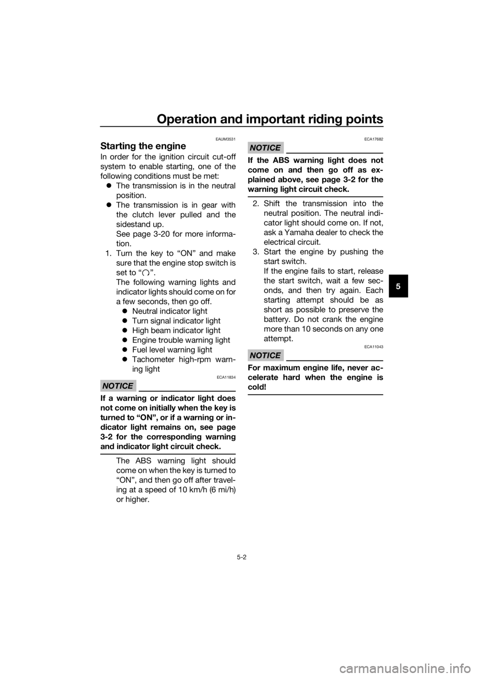
In order for the ignition circuit cut-off
system to enable starting, one of the
following conditions must be met:
The transmission is in the neutral
position.
The transmission is in gear with
the clutch lever pulled and the
sidestand up.
See page 3-20 for more informa-
tion.
1. Turn the key to “ON” and make
sure that the engine stop switch is
set to “ ”.
The following warning lights and
indicator lights should come on for
a few seconds, then go off.
Neutral indicator light
Turn signal indicator light
High beam indicator light
Engine trouble warning light
Fuel level warning light
Tachometer high-rpm warn-
ing light
NOTICE
ECA11834
If a warning or indicator light does
not come on initially when the key is
turned to “ON”, or if a warning or in-
dicator light remains on, see page
3-2 for the corresponding warning
and indicator light circuit check.
The ABS warning light should
come on when the key is turned to
“ON”, and then go off after travel-
ing at a speed of 10 km/h (6 mi/h)
or higher.
NOTICE
ECA17682
If the ABS warning light does not
come on and then go off as ex-
plained above, see page 3-2 for the
warning light circuit check.
2. Shift the transmission into the
neutral position. The neutral indi-
cator light should come on. If not,
ask a Yamaha dealer to check the
electrical circuit.
3. Start the engine by pushing the
start switch.
If the engine fails to start, release
the start switch, wait a few sec-
onds, and then try again. Each
starting attempt should be as
short as possible to preserve the
battery. Do not crank the engine
more than 10 seconds on any one
attempt.
NOTICE
ECA11043
For maximum engine life, never ac-
celerate hard when the engine is
cold!
UBR3E1E0.book Page 2 Wednesday, August 10, 2016 9:45 AM
Page 46 of 96
Periodic maintenance and adjustment
6-4
6
EAU71361
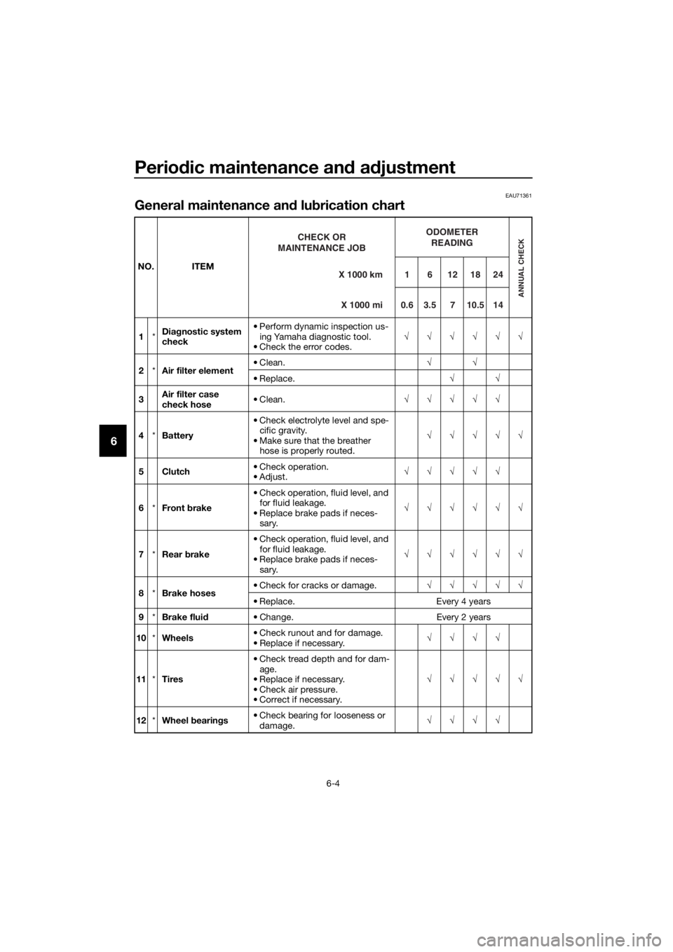
General maintenance and lubrication chart
NO. ITEM
1*Diagnostic system
check• Perform dynamic inspection us-
ing Yamaha diagnostic tool.
• Check the error codes.√√√√√√
2*Air filter element• Clean.√√
• Replace.√√
3Air filter case
check hose• Clean.√√√√√
4*Battery• Check electrolyte level and spe-
cific gravity.
• Make sure that the breather
hose is properly routed.√√√√√
5Clutch• Check operation.
•Adjust.√√√√√
6*Front brake• Check operation, fluid level, and
for fluid leakage.
• Replace brake pads if neces-
sary.√√√√√√
7*Rear brake• Check operation, fluid level, and
for fluid leakage.
• Replace brake pads if neces-
sary.√√√√√√
8*Brake hoses• Check for cracks or damage.√√√√√
• Replace. Every 4 years
9*Brake fluid• Change. Every 2 years
10*Wheels• Check runout and for damage.
• Replace if necessary.√√√√
11*Tires• Check tread depth and for dam-
age.
• Replace if necessary.
• Check air pressure.
• Correct if necessary.√√√√√
12*Wheel bearings• Check bearing for looseness or
damage.√√√√X 1000 km CHECK OR
MAINTENANCE JOB
X 1000 miODOMETER
READINGANNUAL CHECK
1 6 12 18 24
0.6 3.5 7 10.5 14
UBR3E1E0.book Page 4 Wednesday, August 10, 2016 9:45 AM
Page 48 of 96

Periodic maintenance and adjustment
6-6
6
EAU72740
TIP
The air filter needs more frequent service if you are riding in unusually wet or
dusty areas.
Hydraulic brake service
• Regularly check and, if necessary, correct the brake fluid level.
• Every two years change the brake fluid.
• Replace the brake hoses every four years and if cracked or damaged.
25 Engine oil• Change (warm engine before
draining).At the initial interval and when
the oil change indicator flashes
or comes on
• Check oil level and vehicle for oil
leakage.Every 3000 km (1800 mi)
26Engine oil filter el-
ement• Replace.√√√
27*Cooling system• Check coolant level and vehicle
for coolant leakage.√√√√√
• Change. Every 3 years
28*Front and rear
brake switches• Check operation.√√√√√√
29*Moving parts and
cables• Lubricate.√√√√√
30*Throttle grip hous-
ing and cable• Check operation and free play.
• Adjust the throttle cable free
play if necessary.
• Lubricate the throttle grip hous-
ing and cable.√√√√√
31*Lights, signals and
switches• Check operation.
• Adjust headlight beam.√√√√√√ NO. ITEM
X 1000 km CHECK OR
MAINTENANCE JOB
X 1000 miODOMETER
READING
ANNUAL CHECK
16121824
0.6 3.5 7 10.5 14
UBR3E1E0.book Page 6 Wednesday, August 10, 2016 9:45 AM