cool YAMAHA MT-125 2018 Owners Manual
[x] Cancel search | Manufacturer: YAMAHA, Model Year: 2018, Model line: MT-125, Model: YAMAHA MT-125 2018Pages: 96, PDF Size: 7.1 MB
Page 5 of 96

Table of contents
Safety information............................1-1
Description........................................2-1
Left view ..........................................2-1
Right view........................................2-2
Controls and instruments ................2-3
Instrument and control functions....3-1
Main switch/steering lock ...............3-1
Indicator lights and warning
lights ............................................3-2
Multi-function meter unit .................3-4
Handlebar switches.......................3-12
Clutch lever ...................................3-13
Shift pedal .....................................3-14
Brake lever ....................................3-14
Brake pedal ...................................3-15
ABS ...............................................3-15
Fuel tank cap.................................3-16
Fuel................................................3-17
Catalytic converter ........................3-18
Rider seat ......................................3-19
Sidestand ......................................3-20
Ignition circuit cut-off system........3-20
For your safety – pre-operation
checks...............................................4-1
Operation and important riding
points.................................................5-1
Starting the engine ..........................5-2
Shifting ............................................5-3
Tips for reducing fuel
consumption ................................5-4
Engine break-in ...............................5-4
Parking ............................................5-5
Periodic maintenance and
adjustment........................................6-1
Owner’s tool kit ...............................6-2
Periodic maintenance chart for the
emission control system ..............6-3
General maintenance and
lubrication chart ...........................6-4
Removing and installing cowlings ...6-7
Checking the spark plug .................6-8Engine oil and oil filter element ....... 6-9
Coolant ......................................... 6-12
Replacing the air filter element
and cleaning the check hose..... 6-14
Checking the engine idling
speed......................................... 6-14
Adjusting the throttle grip free
play ............................................ 6-15
Valve clearance ............................. 6-16
Tires .............................................. 6-16
Cast wheels .................................. 6-19
Adjusting the clutch lever free
play ............................................ 6-19
Checking the front brake lever
free play ..................................... 6-20
Adjusting the brake pedal free
play ............................................ 6-21
Brake light switches ...................... 6-21
Checking the front and rear brake
pads........................................... 6-22
Checking the brake fluid level....... 6-23
Changing the brake fluid............... 6-24
Drive chain slack ........................... 6-24
Cleaning and lubricating the drive
chain .......................................... 6-26
Checking and lubricating the
cables ........................................ 6-26
Checking and lubricating the
throttle grip and cable ............... 6-27
Checking and lubricating the
brake and clutch levers ............. 6-27
Checking and lubricating the
brake pedal................................ 6-28
Checking and lubricating the
sidestand ................................... 6-28
Lubricating the swingarm
pivots ......................................... 6-29
Checking the front fork ................. 6-29
Checking the steering ................... 6-30
Checking the wheel bearings ....... 6-30
Battery .......................................... 6-31
Replacing the fuses ...................... 6-32
Replacing the headlight bulb ........ 6-33
Auxiliary lights ............................... 6-35
Tail/brake light .............................. 6-35
UBR3E1E0.book Page 1 Wednesday, August 10, 2016 9:45 AM
Page 12 of 96
Description
2-1
2
EAU63371
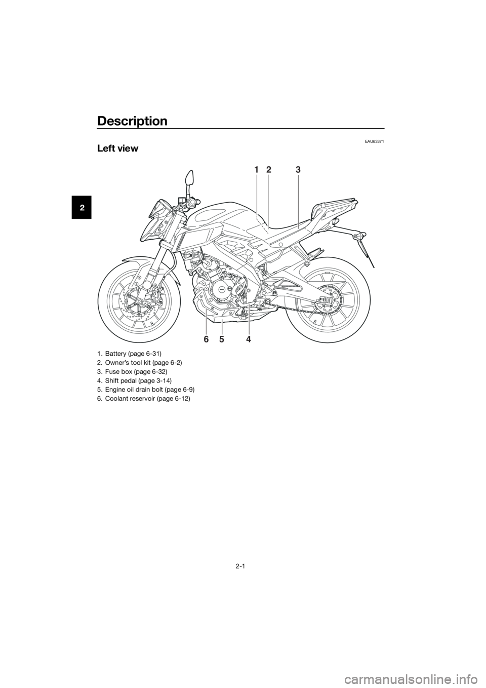
Left view
213
465
1. Battery (page 6-31)
2. Owner’s tool kit (page 6-2)
3. Fuse box (page 6-32)
4. Shift pedal (page 3-14)
5. Engine oil drain bolt (page 6-9)
6. Coolant reservoir (page 6-12)
UBR3E1E0.book Page 1 Wednesday, August 10, 2016 9:45 AM
Page 18 of 96
Instrument and control functions
3-4
3come on to indicate that the function is
activated or the light will go off to indi-
cate that the function is deactivated.
EAUM3423
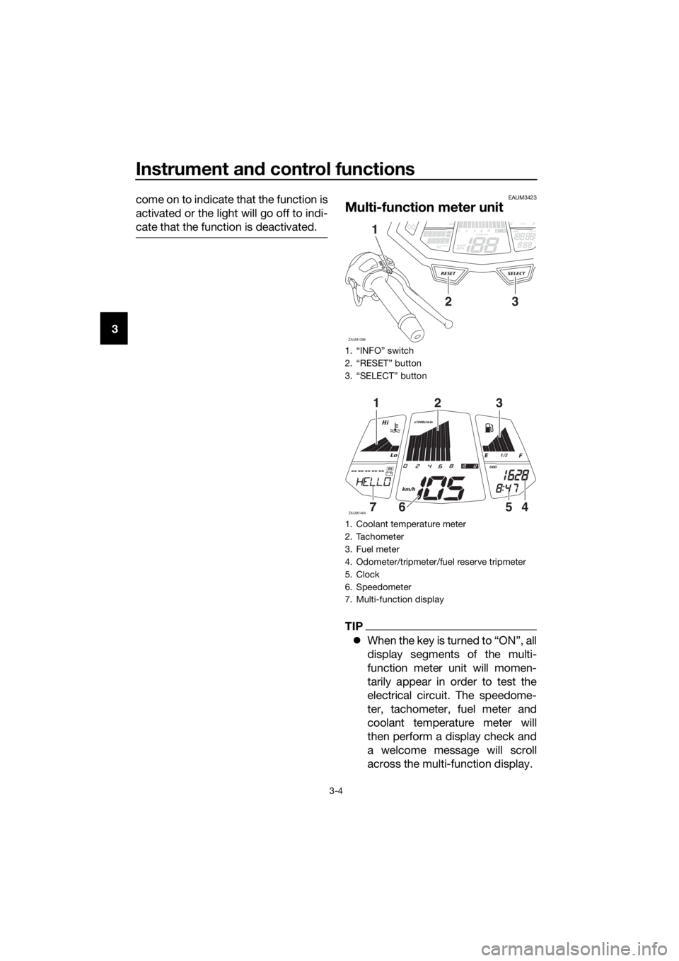
Multi-function meter unit
TIP
When the key is turned to “ON”, all
display segments of the multi-
function meter unit will momen-
tarily appear in order to test the
electrical circuit. The speedome-
ter, tachometer, fuel meter and
coolant temperature meter will
then perform a display check and
a welcome message will scroll
across the multi-function display.
1. “INFO” switch
2. “RESET” button
3. “SELECT” button
1. Coolant temperature meter
2. Tachometer
3. Fuel meter
4. Odometer/tripmeter/fuel reserve tripmeter
5. Clock
6. Speedometer
7. Multi-function display
Lo1/2ODO
ZAUM1299
SELECTRESET
INFO
km/L/100kmMPGkm/h
MPH
ODOFTRIPx1000r/minOILOIL
23
1
Lo
Hi
1/2
x1000r/min
ZAUM1464
km/h
ODOOIL
123
4567
UBR3E1E0.book Page 4 Wednesday, August 10, 2016 9:45 AM
Page 20 of 96
Instrument and control functions
3-6
32. Push the “SELECT” button for two
seconds, and the hour digits will
start flashing.
3. Use the “RESET” button to set the
hours.
4. Push the “SELECT” button, and
the minute digits will start flashing.
5. Use the “RESET” button to set the
minutes.
6. Push the “SELECT” button to con-
firm settings and start the clock.
TIP
When setting the hours and minutes, a
creases the increment value one by
one. You may also push and hold the
button to increase the value continu-
ously.
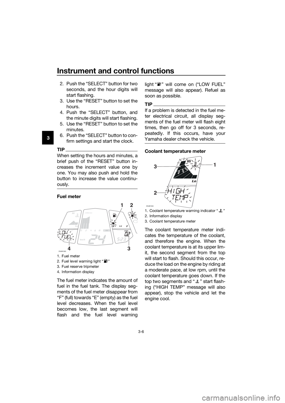
Fuel meter
The fuel meter indicates the amount of
fuel in the fuel tank. The display seg-
ments of the fuel meter disappear from
“F” (full) towards “E” (empty) as the fuel
level decreases. When the fuel level
becomes low, the last segment will
flash and the fuel level warninglight “ ” will come on (“LOW FUEL”
message will also appear). Refuel as
soon as possible.
TIP
If a problem is detected in the fuel me-
ter electrical circuit, all display seg-
ments of the fuel meter will flash eight
times, then go off for 3 seconds, re-
peatedly. If this occurs, have your
Yamaha dealer check the vehicle.
Coolant temperature meter
The coolant temperature meter indi-
cates the temperature of the coolant,
and therefore the engine. When the
coolant temperature is at its upper lim-
it, the second segment from the top
will start to flash. Should this occur, re-
duce the load on the engine by riding at
a moderate pace, at low rpm, until the
coolant temperature goes down. If the
top two segments and “ ” start flash-
ing (“HIGH TEMP” message will also
appear), stop the vehicle and let the
engine cool.
1. Fuel meter
2. Fuel level warning light “ ”
3. Fuel reserve tripmeter
4. Information display
Lo
Hi
1/2
x1000r/min
ZAUM1303
km/h
FTRIP
21
34
1. Coolant temperature warning indicator Ž
2. Information display
3. Coolant temperature meter
Lo
Hi
ZAUM1304
31
2
UBR3E1E0.book Page 6 Wednesday, August 10, 2016 9:45 AM
Page 21 of 96

Instrument and control functions
3-7
3
NOTICE
ECA10022
Do not continue to operate the en-
gine if it is overheating.
TIP
Coolant temperature varies with
changes in the weather and en-
gine load.
The radiator fan will automatically
switch on or off according to the
coolant temperature.
If the engine overheats, see page
6-39 for further instruction.
Odometer and tripmeter display
The odometer and tripmeter display is
equipped with:
an odometer
two tripmeters
a fuel reserve tripmeter
Push the “SELECT” button to switch
between the odometer and the tripme-
ters in the following order:
ODO (odometer) → TRIP 1 (tripmeter)
→ TRIP 2 (tripmeter) → ODO (odome-
ter)When approximately 3.0 L (0.79 US
gal, 0.66 Imp.gal) of fuel remains in the
fuel tank, the display will automatically
change to the fuel reserve tripmeter
mode “F TRIP” and start counting the
distance traveled from that point. In
this case, push the “SELECT” button
to switch the display in the following
order:
F TRIP → ODO → TRIP 1 → TRIP 2 →
F TRIP
To manually reset a tripmeter, select it
with the “SELECT” button, and then
push the “RESET” button for two sec-
onds.
TIP
The fuel reserve tripmeter will re-
set automatically and disappear
after you have refueled and turned
the key to “OFF”.
The tripmeters will automatically
reset and continue counting after
999.9 is reached.
The odometer will lock at 199999
and cannot be reset.
1. Odometer/tripmeter/fuel reserve tripmeter
1/2
ZAUM1305
TRIP1
1
1. Odometer/tripmeter/fuel reserve tripmeter
1/2
ZAUM1306
F TRIP
1
UBR3E1E0.book Page 7 Wednesday, August 10, 2016 9:45 AM
Page 25 of 96
Instrument and control functions
3-11
3 15 seconds. “OIL SERV” message and
the oil change tripmeter will also be re-
set.
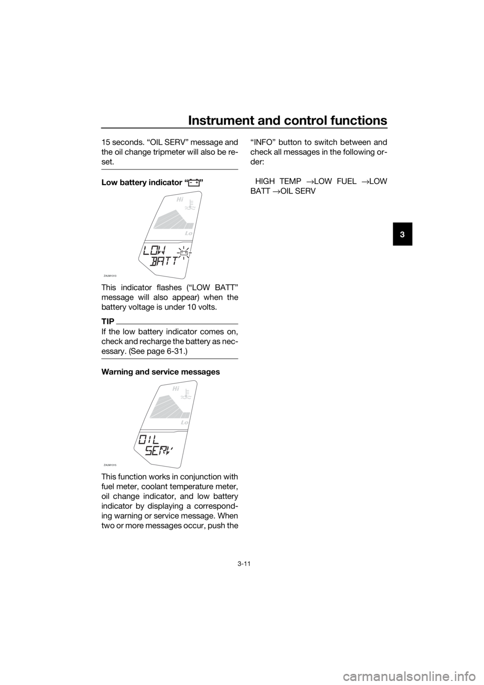
Low battery indicator “ ”
This indicator flashes (“LOW BATT”
message will also appear) when the
battery voltage is under 10 volts.
TIP
If the low battery indicator comes on,
check and recharge the battery as nec-
essary. (See page 6-31.)
Warning and service messages
This function works in conjunction with
fuel meter, coolant temperature meter,
oil change indicator, and low battery
indicator by displaying a correspond-
ing warning or service message. When
two or more messages occur, push the“INFO” button to switch between and
check all messages in the following or-
der:
HIGH TEMP →LOW FUEL →LOW
BATT →OIL SERV
Lo
Hi
ZAUM1313
Lo
Hi
ZAUM1315
UBR3E1E0.book Page 11 Wednesday, August 10, 2016 9:45 AM
Page 32 of 96
Instrument and control functions
3-18
3TIP
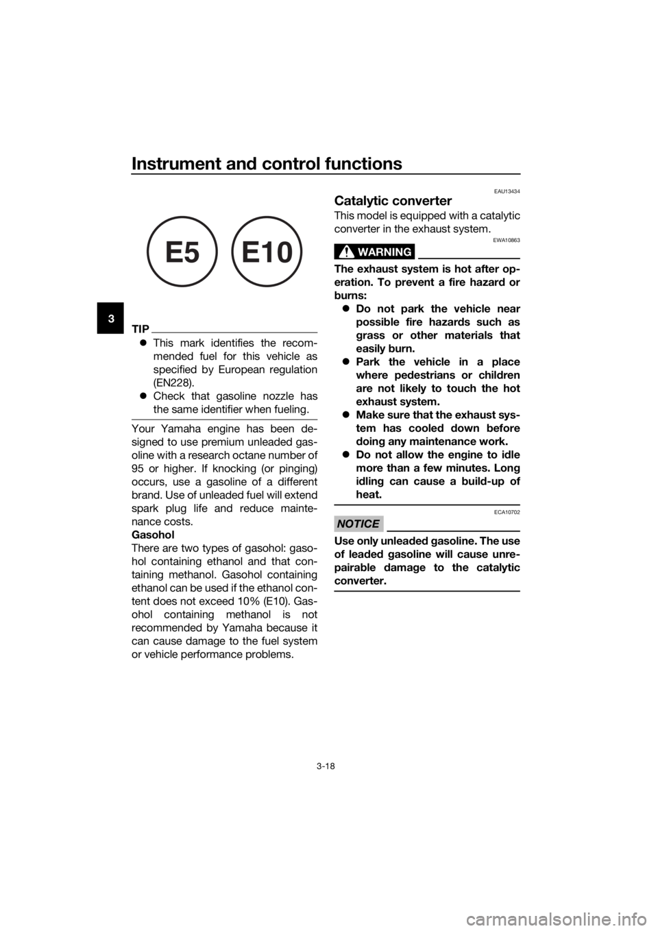
This mark identifies the recom-
mended fuel for this vehicle as
specified by European regulation
(EN228).
Check that gasoline nozzle has
the same identifier when fueling.
Your Yamaha engine has been de-
signed to use premium unleaded gas-
oline with a research octane number of
95 or higher. If knocking (or pinging)
occurs, use a gasoline of a different
brand. Use of unleaded fuel will extend
spark plug life and reduce mainte-
nance costs.
Gasohol
There are two types of gasohol: gaso-
hol containing ethanol and that con-
taining methanol. Gasohol containing
ethanol can be used if the ethanol con-
tent does not exceed 10% (E10). Gas-
ohol containing methanol is not
recommended by Yamaha because it
can cause damage to the fuel system
or vehicle performance problems.
EAU13434
Catalytic converter
This model is equipped with a catalytic
converter in the exhaust system.
WARNING
EWA10863
The exhaust system is hot after op-
eration. To prevent a fire hazard or
burns:
Do not park the vehicle near
possible fire hazards such as
grass or other materials that
easily burn.
Park the vehicle in a place
where pedestrians or children
are not likely to touch the hot
exhaust system.
Make sure that the exhaust sys-
tem has cooled down before
doing any maintenance work.
Do not allow the engine to idle
more than a few minutes. Long
idling can cause a build-up of
heat.
NOTICE
ECA10702
Use only unleaded gasoline. The use
of leaded gasoline will cause unre-
pairable damage to the catalytic
converter.
E5E10
UBR3E2E0.book Page 18 Friday, May 11, 2018 11:08 AM
Page 36 of 96
For your safety – pre-operation checks
4-1
4
EAU63440
Inspect your vehicle each time you use it to make sure the vehicle is in safe oper-
ating condition. Always follow the inspection and maintenance procedures and
schedules described in the Owner’s Manual.
WARNING
EWA11152
Failure to inspect or maintain the vehicle properly increases the possibility
of an accident or equipment damage. Do not operate the vehicle if you find
any problem. If a problem cannot be corrected by the procedures provided
in this manual, have the vehicle inspected by a Yamaha dealer.
Before using this vehicle, check the following points:
ITEM CHECKS PAGE
Fuel• Check fuel level in fuel tank.
• Refuel if necessary.
• Check fuel line for leakage.3-17
Engine oil• Check oil level in engine.
• If necessary, add recommended oil to specified level.
• Check vehicle for oil leakage.6-9
Coolant• Check coolant level in reservoir.
• If necessary, add recommended coolant to specified
level.
• Check cooling system for leakage.6-12
Front brake• Check operation.
• If soft or spongy, have Yamaha dealer bleed hydraulic
system.
• Check brake pads for wear.
• Replace if necessary.
• Check fluid level in reservoir.
• If necessary, add specified brake fluid to specified level.
• Check hydraulic system for leakage.6-22,
6-23
Rear brake• Check operation.
• If soft or spongy, have Yamaha dealer bleed hydraulic
system.
• Check brake pads for wear.
• Replace if necessary.
• Check fluid level in reservoir.
• If necessary, add specified brake fluid to specified level.
• Check hydraulic system for leakage.6-22,
6-23
Clutch• Check operation.
• Lubricate cable if necessary.
• Check lever free play.
• Adjust if necessary.6-19
Throttle grip• Make sure that operation is smooth.
• Check throttle grip free play.
• If necessary, have Yamaha dealer adjust throttle grip
free play and lubricate cable and grip housing.6-15,
6-27
UBR3E1E0.book Page 1 Wednesday, August 10, 2016 9:45 AM
Page 41 of 96

Operation and important riding points
5-4
5
EAU16811
Tips for reducing fuel con-
sumption
Fuel consumption depends largely on
your riding style. Consider the follow-
ing tips to reduce fuel consumption:
Shift up swiftly, and avoid high en-
gine speeds during acceleration.
Do not rev the engine while shift-
ing down, and avoid high engine
speeds with no load on the en-
gine.
Turn the engine off instead of let-
ting it idle for an extended length
of time (e.g., in traffic jams, at traf-
fic lights or at railroad crossings).
EAU16831
Engine break-in
There is never a more important period
in the life of your engine than the period
between 0 and 1000 km (600 mi). For
this reason, you should read the fol-
lowing material carefully.
Since the engine is brand new, do not
put an excessive load on it for the first
1000 km (600 mi). The various parts in
the engine wear and polish themselves
to the correct operating clearances.
During this period, prolonged full-throt-
tle operation or any condition that
might result in engine overheating
must be avoided.
EAU16983
0–500 km (0–300 mi)
Avoid prolonged operation above 6000
r/min.
After every hour of operation, stop the
engine, and then let it cool for five to
ten minutes.
Vary the engine speed from time to
time. Do not operate the engine at one
set throttle position.
500–1000 km (300–600 mi)
Avoid prolonged operation above 8000
r/min.
Rev the engine freely through the
gears, but do not use full throttle at any
time. NOTICE: After 1000 km (600 mi)
of operation, the engine oil must be
changed, the oil filter cartridge or el-
ement replaced, and the oil strainer
cleaned.
[ECA10322]
UBR3E1E0.book Page 4 Wednesday, August 10, 2016 9:45 AM
Page 43 of 96
Periodic maintenance and adjustment
6-1
6
EAU17246
Periodic inspection, adjustment, and
lubrication will keep your vehicle in the
safest and most efficient condition
possible. Safety is an obligation of the
vehicle owner/operator. The most im-
portant points of vehicle inspection,
adjustment, and lubrication are ex-
plained on the following pages.
The intervals given in the periodic
maintenance charts should be simply
considered as a general guide under
normal riding conditions. However, de-
pending on the weather, terrain, geo-
graphical location, and individual use,
the maintenance intervals may need to
be shortened.
WARNING
EWA10322
Failure to properly maintain the vehi-
cle or performing maintenance ac-
tivities incorrectly may increase
your risk of injury or death during
service or while using the vehicle. If
you are not familiar with vehicle ser-
vice, have a Yamaha dealer perform
service.
WARNING
EWA15123
Turn off the engine when performing
maintenance unless otherwise
specified.
A running engine has moving
parts that can catch on body
parts or clothing and electrical
parts that can cause shocks or
fires.
Running the engine while ser-
vicing can lead to eye injury,
burns, fire, or carbon monoxide
poisoning – possibly leading todeath. See page 1-3 for more in-
formation about carbon monox-
ide.
WARNING
EWA15461
Brake discs, calipers, drums, and
linings can become very hot during
use. To avoid possible burns, let
brake components cool before
touching them.
UBR3E1E0.book Page 1 Wednesday, August 10, 2016 9:45 AM