check engine YAMAHA MT07 TRACER 2018 Owner's Manual
[x] Cancel search | Manufacturer: YAMAHA, Model Year: 2018, Model line: MT07 TRACER, Model: YAMAHA MT07 TRACER 2018Pages: 102, PDF Size: 5.6 MB
Page 60 of 102
Periodic maintenance and adjustment
6-12
6
EAU20071
Coolant
The coolant level should be checked
before each ride. In addition, the cool-
ant must be changed at the intervals
specified in the periodic maintenance
and lubrication chart.
EAU20095To check the coolant level
1. Place the vehicle on a level sur-
face and hold it in an upright posi-
tion.
TIP
The coolant level must be
checked on a cold engine since
the level varies with engine tem-
perature.
Make sure that the vehicle is posi-
tioned straight up when checking
the coolant level. A slight tilt to the
side can result in a false reading.
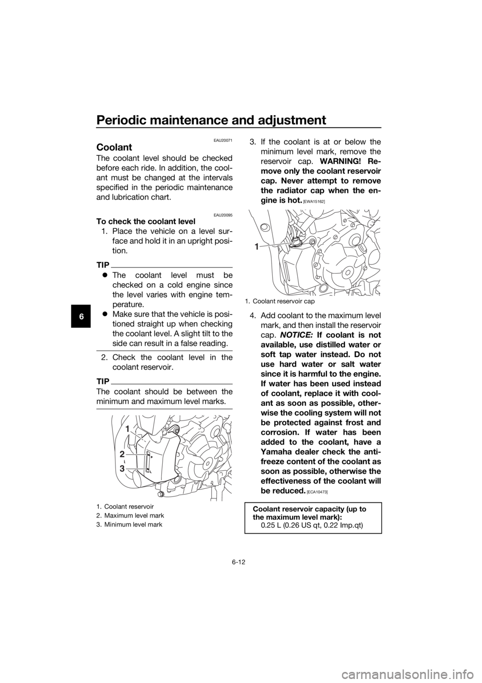
2. Check the coolant level in the
coolant reservoir.
TIP
The coolant should be between the
minimum and maximum level marks.
3. If the coolant is at or below the
minimum level mark, remove the
reservoir cap. WARNING! Re-
move only the coolant reservoir
cap. Never attempt to remove
the radiator cap when the en-
gine is hot.
[EWA15162]
4. Add coolant to the maximum level
mark, and then install the reservoir
cap. NOTICE: If coolant is not
available, use distilled water or
soft tap water instead. Do not
use hard water or salt water
since it is harmful to the engine.
If water has been used instead
of coolant, replace it with cool-
ant as soon as possible, other-
wise the cooling system will not
be protected against frost and
corrosion. If water has been
added to the coolant, have a
Yamaha dealer check the anti-
freeze content of the coolant as
soon as possible, otherwise the
effectiveness of the coolant will
be reduced.
[ECA10473]
1. Coolant reservoir
2. Maximum level mark
3. Minimum level mark
1
2
3
1. Coolant reservoir cap
Coolant reservoir capacity (up to
the maximum level mark):
0.25 L (0.26 US qt, 0.22 Imp.qt)
1
UBC6E2E0.book Page 12 Tuesday, July 10, 2018 6:26 PM
Page 62 of 102
Periodic maintenance and adjustment
6-14
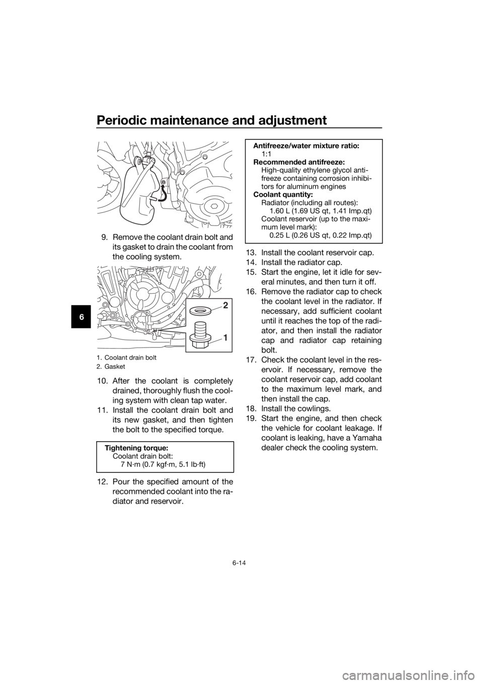
69. Remove the coolant drain bolt and
its gasket to drain the coolant from
the cooling system.
10. After the coolant is completely
drained, thoroughly flush the cool-
ing system with clean tap water.
11. Install the coolant drain bolt and
its new gasket, and then tighten
the bolt to the specified torque.
12. Pour the specified amount of the
recommended coolant into the ra-
diator and reservoir.13. Install the coolant reservoir cap.
14. Install the radiator cap.
15. Start the engine, let it idle for sev-
eral minutes, and then turn it off.
16. Remove the radiator cap to check
the coolant level in the radiator. If
necessary, add sufficient coolant
until it reaches the top of the radi-
ator, and then install the radiator
cap and radiator cap retaining
bolt.
17. Check the coolant level in the res-
ervoir. If necessary, remove the
coolant reservoir cap, add coolant
to the maximum level mark, and
then install the cap.
18. Install the cowlings.
19. Start the engine, and then check
the vehicle for coolant leakage. If
coolant is leaking, have a Yamaha
dealer check the cooling system.
1. Coolant drain bolt
2. Gasket
Tightening torque:
Coolant drain bolt:
7 N·m (0.7 kgf·m, 5.1 lb·ft)
1
2
Antifreeze/water mixture ratio:
1:1
Recommended antifreeze:
High-quality ethylene glycol anti-
freeze containing corrosion inhibi-
tors for aluminum engines
Coolant quantity:
Radiator (including all routes):
1.60 L (1.69 US qt, 1.41 Imp.qt)
Coolant reservoir (up to the maxi-
mum level mark):
0.25 L (0.26 US qt, 0.22 Imp.qt)
UBC6E2E0.book Page 14 Tuesday, July 10, 2018 6:26 PM
Page 64 of 102
Periodic maintenance and adjustment
6-16
6
EAU21402
Valve clearance
The valve clearance changes with use,
resulting in improper air-fuel mixture
and/or engine noise. To prevent this
from occurring, the valve clearance
must be adjusted by a Yamaha dealer
at the intervals specified in the periodic
maintenance and lubrication chart.
EAU64662
Tires
Tires are the only contact between the
vehicle and the road. Safety in all con-
ditions of riding depends on a relatively
small area of road contact. Therefore, it
is essential to maintain the tires in good
condition at all times and replace them
at the appropriate time with the speci-
fied tires.
Tire air pressure
The tire air pressure should be
checked and, if necessary, adjusted
before each ride.
WARNING
EWA10504
Operation of this vehicle with im-
proper tire pressure may cause se-
vere injury or death from loss of
control.
The tire air pressure must be
checked and adjusted on cold
tires (i.e., when the temperature
of the tires equals the ambient
temperature).
The tire air pressure must be
adjusted in accordance with the
riding speed and with the total
weight of rider, passenger, car-
go, and accessories approved
for this model.
UBC6E2E0.book Page 16 Tuesday, July 10, 2018 6:26 PM
Page 72 of 102
Periodic maintenance and adjustment
6-24
6
EAU22762
Drive chain slack
The drive chain slack should be
checked before each ride and adjusted
if necessary.
EAU60046To check the drive chain slack
1. Place the motorcycle on the side-
stand.
TIP
When checking and adjusting the drive
chain slack, there should be no weight
on the motorcycle.
2. Shift the transmission into the
neutral position.
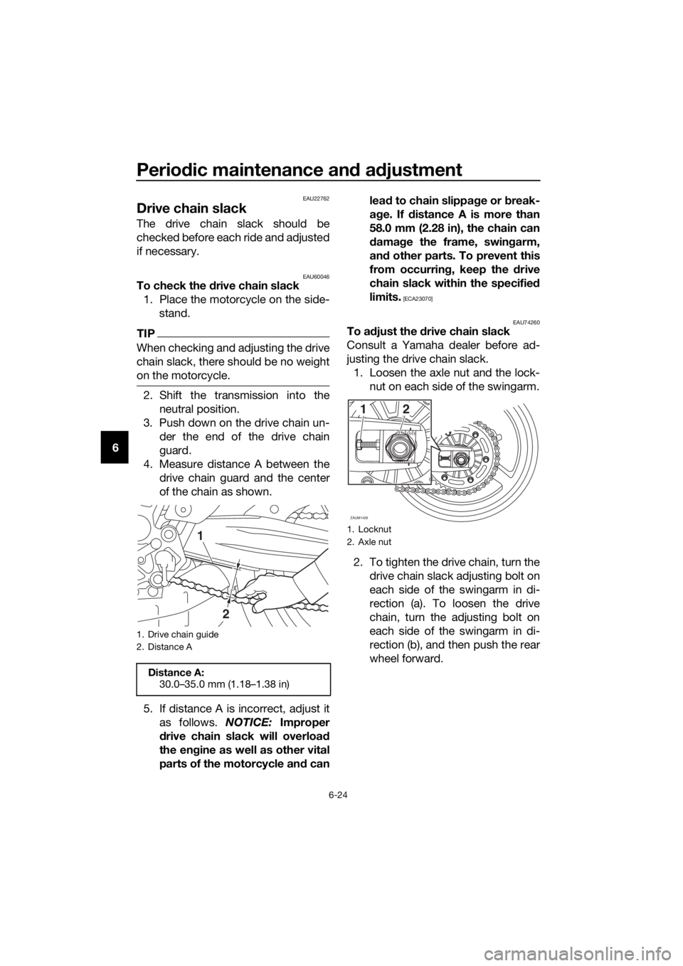
3. Push down on the drive chain un-
der the end of the drive chain
guard.
4. Measure distance A between the
drive chain guard and the center
of the chain as shown.
5. If distance A is incorrect, adjust it
as follows. NOTICE: Improper
drive chain slack will overload
the engine as well as other vital
parts of the motorcycle and canlead to chain slippage or break-
age. If distance A is more than
58.0 mm (2.28 in), the chain can
damage the frame, swingarm,
and other parts. To prevent this
from occurring, keep the drive
chain slack within the specified
limits.
[ECA23070]
EAU74260
To adjust the drive chain slack
Consult a Yamaha dealer before ad-
justing the drive chain slack.
1. Loosen the axle nut and the lock-
nut on each side of the swingarm.
2. To tighten the drive chain, turn the
drive chain slack adjusting bolt on
each side of the swingarm in di-
rection (a). To loosen the drive
chain, turn the adjusting bolt on
each side of the swingarm in di-
rection (b), and then push the rear
wheel forward.
1. Drive chain guide
2. Distance A
Distance A:
30.0–35.0 mm (1.18–1.38 in)
2
11. Locknut
2. Axle nut
ZAUM1426
12
UBC6E2E0.book Page 24 Tuesday, July 10, 2018 6:26 PM
Page 87 of 102
Periodic maintenance and adjustment
6-39
6
EAU67970
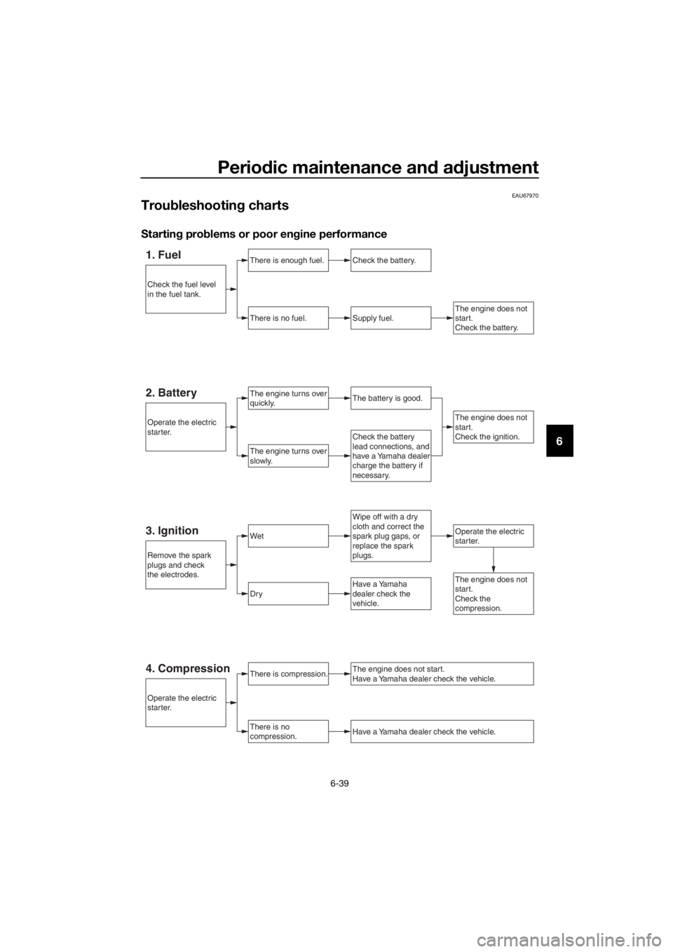
Troubleshooting charts
Starting problems or poor engine performance
1. FuelThere is enough fuel.
There is no fuel.
Check the battery.
Supply fuel.
The engine turns over
quickly.
The engine turns over
slowly.
The engine does not
start.
Check the battery.
Wipe off with a dry
cloth and correct the
spark plug gaps, or
replace the spark
plugs.
Check the battery
lead connections, and
have a Yamaha dealer
charge the battery if
necessary.
2. BatteryThe battery is good.
The engine does not
start.
Check the ignition.
3. IgnitionWetOperate the electric
starter.
Dry
There is compression.
There is no
compression.
The engine does not start.
Have a Yamaha dealer check the vehicle.
Have a Yamaha dealer check the vehicle.
The engine does not
start.
Check the
compression.Have a Yamaha
dealer check the
vehicle.
Remove the spark
plugs and check
the electrodes.
Operate the electric
starter.
Operate the electric
starter.
Check the fuel level
in the fuel tank.
4. Compression
UBC6E2E0.book Page 39 Tuesday, July 10, 2018 6:26 PM
Page 88 of 102
Periodic maintenance and adjustment
6-40
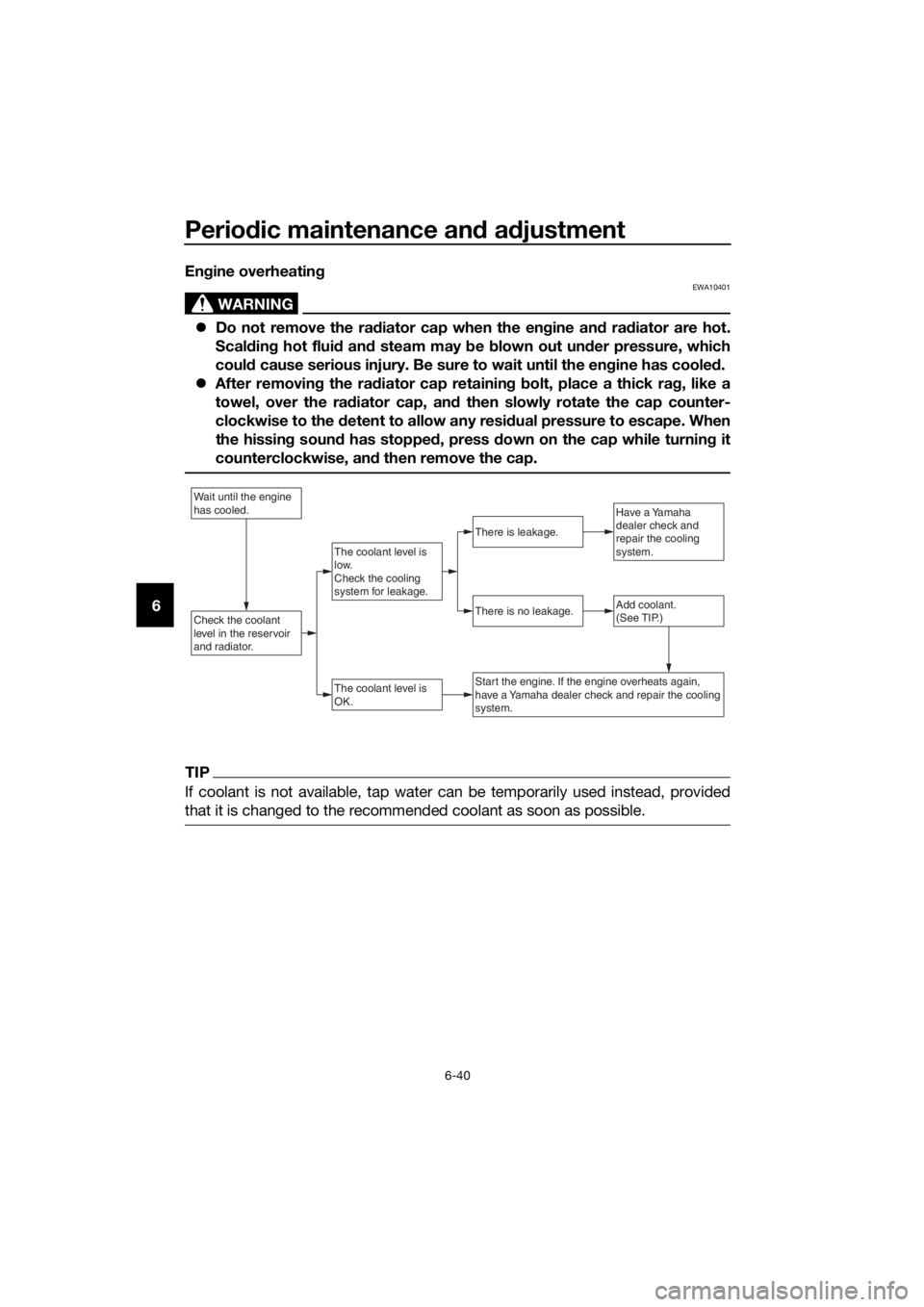
6Engine overheating
WARNING
EWA10401
Do not remove the radiator cap when the engine and radiator are hot.
Scalding hot fluid and steam may be blown out under pressure, which
could cause serious injury. Be sure to wait until the engine has cooled.
After removing the radiator cap retaining bolt, place a thick rag, like a
towel, over the radiator cap, and then slowly rotate the cap counter-
clockwise to the detent to allow any residual pressure to escape. When
the hissing sound has stopped, press down on the cap while turning it
counterclockwise, and then remove the cap.
TIP
If coolant is not available, tap water can be temporarily used instead, provided
that it is changed to the recommended coolant as soon as possible.
Wait until the engine
has cooled.
Check the coolant
level in the reservoir
and radiator.Add coolant.
(See TIP.)
The coolant level is
OK.
There is no leakage.
There is leakage.
The coolant level is
low.
Check the cooling
system for leakage.
Have a Yamaha
dealer check and
repair the cooling
system.
Start the engine. If the engine overheats again,
have a Yamaha dealer check and repair the cooling
system.
UBC6E2E0.book Page 40 Tuesday, July 10, 2018 6:26 PM
Page 92 of 102
Motorcycle care and storage
7-4
7
EAU26183
Storage
Short-term
Always store your motorcycle in a cool,
dry place and, if necessary, protect it
against dust with a porous cover. Be
sure the engine and the exhaust sys-
tem are cool before covering the mo-
torcycle.
NOTICE
ECA10811
Storing the motorcycle in a
poorly ventilated room or cover-
ing it with a tarp, while it is still
wet, will allow water and humid-
ity to seep in and cause rust.
To prevent corrosion, avoid
damp cellars, stables (because
of the presence of ammonia)
and areas where strong chemi-
cals are stored.
Long-term
Before storing your motorcycle for sev-
eral months:
1. Follow all the instructions in the
“Care” section of this chapter.
2. Fill up the fuel tank and add fuel
stabilizer (if available) to prevent
the fuel tank from rusting and the
fuel from deteriorating.
3. Perform the following steps to
protect the cylinders, piston rings,
etc. from corrosion.
a. Remove the spark plug caps
and spark plugs.
b. Pour a teaspoonful of engine
oil into each spark plug bore.
c. Install the spark plug caps onto
the spark plugs, and then
place the spark plugs on thecylinder head so that the elec-
trodes are grounded. (This will
limit sparking during the next
step.)
d. Turn the engine over several
times with the starter. (This will
coat the cylinder walls with oil.)
WARNING! To prevent dam-
age or injury from sparking,
make sure to ground the
spark plug electrodes while
turning the engine over.
[EWA10952]
e. Remove the spark plug caps
from the spark plugs, and then
install the spark plugs and the
spark plug caps.
4. Lubricate all control cables and
the pivoting points of all levers and
pedals as well as of the side-
stand/centerstand.
5. Check and, if necessary, correct
the tire air pressure, and then lift
the motorcycle so that both of its
wheels are off the ground. Alterna-
tively, turn the wheels a little every
month in order to prevent the tires
from becoming degraded in one
spot.
6. Cover the muffler outlet with a
plastic bag to prevent moisture
from entering it.
7. Remove the battery and fully
charge it. Store it in a cool, dry
place and charge it once a month.
Do not store the battery in an ex-
cessively cold or warm place [less
than 0 °C (30 °F) or more than 30
°C (90 °F)]. For more information
on storing the battery, see page
6-31.
UBC6E2E0.book Page 4 Tuesday, July 10, 2018 6:26 PM
Page 98 of 102
Consumer information
9-2
9provided. This information will be
needed when ordering spare parts
from a Yamaha dealer.
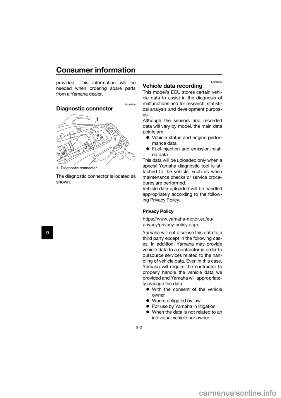
EAU69910
Diagnostic connector
The diagnostic connector is located as
shown.
EAU85300
Vehicle data recording
This model’s ECU stores certain vehi-
cle data to assist in the diagnosis of
malfunctions and for research, statisti-
cal analysis and development purpos-
es.
Although the sensors and recorded
data will vary by model, the main data
points are:
Vehicle status and engine perfor-
mance data
Fuel-injection and emission-relat-
ed data
This data will be uploaded only when a
special Yamaha diagnostic tool is at-
tached to the vehicle, such as when
maintenance checks or service proce-
dures are performed.
Vehicle data uploaded will be handled
appropriately according to the follow-
ing Privacy Policy.
Privacy Policy
Yamaha will not disclose this data to a
third party except in the following cas-
es. In addition, Yamaha may provide
vehicle data to a contractor in order to
outsource services related to the han-
dling of vehicle data. Even in this case,
Yamaha will require the contractor to
properly handle the vehicle data we
provided and Yamaha will appropriate-
ly manage the data.
With the consent of the vehicle
owner
Where obligated by law
For use by Yamaha in litigation
When the data is not related to an
individual vehicle nor owner
1. Diagnostic connector
1
ZAUM1424
https://www.yamaha-motor.eu/eu/
privacy/privacy-policy.aspx
UBC6E2E0.book Page 2 Tuesday, July 10, 2018 6:26 PM
Page 99 of 102

10-1
10
Index
A
ABS ...................................................... 3-16
ABS warning light ................................... 3-5
Air filter element and check hose,
replacing and cleaning ....................... 6-15
Auxiliary DC connector ........................ 3-27
Auxiliary lights ...................................... 6-35
B
Battery .................................................. 6-31
Brake and clutch levers, checking and
lubricating .......................................... 6-27
Brake and shift pedals, checking and
lubricating .......................................... 6-27
Brake fluid, changing ........................... 6-23
Brake fluid level, checking ................... 6-22
Brake lever ........................................... 3-15
Brake lever free play, checking ............ 6-20
Brake light switches ............................. 6-21
Brake pedal .......................................... 3-15
Brake/tail light ...................................... 6-36
C
Cables, checking and lubricating ......... 6-26
Canister .................................................. 6-9
Care ........................................................ 7-1
Catalytic converter ............................... 3-19
Clutch lever .......................................... 3-14
Clutch lever free play, adjusting ........... 6-19
Coolant ................................................. 6-12
Coolant temperature warning light ......... 3-4
Cowlings, removing and installing ......... 6-7
D
Data recording, vehicle .......................... 9-2
Diagnostic connector ............................. 9-2
Dimmer switch ..................................... 3-13
Drive chain, cleaning and lubricating ... 6-25
Drive chain slack .................................. 6-24
E
Engine break-in ...................................... 5-5
Engine oil and oil filter cartridge ............. 6-9
Engine serial number.............................. 9-1
Engine trouble warning light................... 3-5
F
Front and rear brake pads, checking ... 6-21
Front fork, checking ............................. 6-29
Fuel....................................................... 3-17
Fuel consumption, tips for reducing ...... 5-4
Fuel tank breather hose and overflow
hose ................................................... 3-19
Fuel tank cap........................................ 3-17
Fuses, replacing ................................... 6-32
H
Handlebar switches .............................. 3-13
Hazard switch ....................................... 3-13
Headlight bulb, replacing ...................... 6-34
Helmet holding cable ............................ 3-21
High beam indicator light........................ 3-4
Horn switch........................................... 3-13
I
Identification numbers ............................ 9-1
Ignition circuit cut-off system ............... 3-25
Immobilizer system ................................. 3-1
Immobilizer system indicator light .......... 3-6
Indicator lights and warning lights .......... 3-4
L
License plate light bulb, replacing ........ 6-37
Luggage strap holders .......................... 3-24
M
Main switch/steering lock ....................... 3-2
Maintenance and lubrication, periodic ... 6-4
Maintenance, emission control
system .................................................. 6-3
Matte color, caution ................................ 7-1
Model label ............................................. 9-1
Multi-function meter unit ........................ 3-7
N
Neutral indicator light.............................. 3-4
O
Oil pressure warning light ....................... 3-4
P
Parking .................................................... 5-5
Part locations .......................................... 2-1
Pass switch........................................... 3-13
R
Rear suspension, lubricating ................ 6-28
S
Safety information................................... 1-1
Seat....................................................... 3-20
Shifting .................................................... 5-3
Shift pedal............................................. 3-14
Shock absorber assembly, adjusting ... 3-23
Sidestand .............................................. 3-24
Sidestand, checking and lubricating .... 6-28
Spark plugs, checking ............................ 6-8
Specifications ......................................... 8-1
Start/Engine stop switch ...................... 3-13
Starting the engine.................................. 5-2
Steering, checking ................................ 6-30
Storage ................................................... 7-4
Storage compartment ........................... 3-22
Supporting the motorcycle ................... 6-37
UBC6E2E0.book Page 1 Tuesday, July 10, 2018 6:26 PM